Advertisement
INSTALLATION AND OPERATION MANUAL
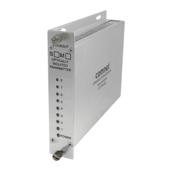
FDC8ISOT(M,S)1
8-CHANNEL OPTICALLY ISOLATED
CONTACT CLOSURE TRANSMITTER
The FDC8ISOT 8-Channel Contact Closure Transmitter unit provides up to eight
independent normally-open (NO) dry contact closures over one multimode or
single-mode optical fiber, when used in conjunction with the companion ComNet
model FDC8NLR Non-Latching Receiver or FDC8R Latching Receiver units. Each
of the contact closure inputs are optically isolated at 1500V to ground, for those
applications where high stray or transient voltages may exist. Microprocessor-
based logic in the FDC8ISOT Transmitter detects a customer-furnished switch
or contact closure, and encodes the closure into robust data packets that are
mapped and transmitted to the FDC8NLR Receiver. Packets received with
excessive bit errors will not result in random changes in the receiver relay
contact resting or actuated states, making this system ideal for mission-critical
remote switching applications. See Figure 3 on Page 3 for contact settings.
These transmitter modules incorporate status indicating LEDs for rapidly
providing a local indication of each contact closure channel and operating power.
See Figure 4 on Page 3 for an explanation of the LED indicators.
Packaged in the exclusive ComNet ComFit housing, these units may be either
shelf or rack-mounted, or may be DIN-rail mounted by the addition of ComNet
model DINBKT1 Adaptor Plate Kit. See Figure A on Page 4 for mounting
instructions.
See Figures 1 – 4 for complete installation information.
INS_FDC8ISOT_REV–
03/08/11
PAGE 1
Advertisement
Table of Contents

Subscribe to Our Youtube Channel
Related Manuals for Comnet FDC8ISOT1


Summary of Contents for Comnet FDC8ISOT1
- Page 1 See Figure 4 on Page 3 for an explanation of the LED indicators. Packaged in the exclusive ComNet ComFit housing, these units may be either shelf or rack-mounted, or may be DIN-rail mounted by the addition of ComNet model DINBKT1 Adaptor Plate Kit. See Figure A on Page 4 for mounting instructions.
- Page 2 INSTALLATION AND OPERATION MANUAL FDC8NLR FIGURE 1 – FDC8ISOT TRANSMITTER MULTIMODE OR SINGLE MODE OPTICAL FIBER BLACK BLACK WITH WHITE STRIPE Power Supply: Surface Mount: 8–15 VDC @ 150mA Rack Mount: From Rack FIGURE 2 – FDC8ISOT TRANSMITTER FRONT PANEL REAR PANEL NOTE: Remove Electrical Connector for Rack Mount Units INS_FDC8ISOT_REV–...
- Page 3 INSTALLATION AND OPERATION MANUAL FDC8NLR FIGURE 3 – TYPICAL RELAY SETTINGS RELAY RELAY OUTPUT 1.62K Customer Input: – 10mA INPUT EQUIVALENT CIRCUIT – – 15V – FIGURE 4 – LED INDICATORS CONTACT (1 – 8) POWER GREEN An active signal is present. Unit powered up No activity –...
- Page 4 8 TURNBERRY PARK ROAD | GILDERSOME | MORLEY | LEEDS, UK LS27 7LE T: +44 (0)113 307 6400 | F: +44 (0)113 253 7462 | INFO-EUROPE@COMNET.NET INS_FDC8ISOT_REV– 03/08/11 © 2011 Communications Networks Corporation. All Rights Reserved. “ComNet” and the “ComNet Logo” are registered trademarks of Communication Networks, LLC. PAGE 4...
Need help?
Do you have a question about the FDC8ISOT1 and is the answer not in the manual?
Questions and answers