Advertisement
Quick Links
INSTALLATION AND OPERATION MANUAL
FVT/FVR1021(M)(S)1
10-BIT DIGITAL VIDEO WITH RETURN DATA
AND UP-THE-COAX DATA
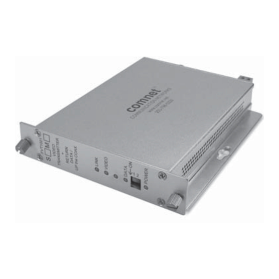
The FVT/FVR1021 series video transmitter/receiver and data transceiver
supports the simultaneous transmission of short-haul quality 10-bit digital
video and return data or up-the-coax data over one multimode or single mode
optical fiber. This module is universally compatible with major CCTV camera
manufacturers and supports RS232 and RS422 data interfaces as well as
up-the-coax data.
Bi-color (Red/Green) LED indicators are provided for rapidly ascertaining
equipment operating status. These units are interchangeable between stand-
alone or card mount configurations. See Figure A on Page 5 for mounting
instructions.
Figures 4 through 6 on Page 3 illustrates the specific data connections for
RS232, RS422, Manchester and Bi-Phase data transmission, in addition to
connections for Up-the-Coax data.
Figure 7 on Page 4 describes the LED indicators for each light on the unit.
INS_FVT/FVR1021_REV–
02/05/10
PAGE 1
Advertisement

Related Manuals for Comnet FVR1021 Series


Summary of Contents for Comnet FVR1021 Series
- Page 1 FVT/FVR1021(M)(S)1 10-BIT DIGITAL VIDEO WITH RETURN DATA AND UP-THE-COAX DATA The FVT/FVR1021 series video transmitter/receiver and data transceiver supports the simultaneous transmission of short-haul quality 10-bit digital video and return data or up-the-coax data over one multimode or single mode optical fiber.
- Page 2 INSTALLATION AND OPERATION MANUAL FVT/FVR1021(M)(S)1 FIGURE 1 – FVT/FVR1021 TRANSMITTER AND RECEIVER MULTIMODE OR SINGLE MODE OPTICAL FIBER BLACK BLACK WITH WHITE STRIPES FIGURE 2 – FVT1021 TRANSMITTER FIGURE 3 – FVR1021 RECEIVER FRONT PANEL REAR PANEL FRONT PANEL REAR PANEL NOTE: Remove Electrical Connector for Rack Mount Units INS_FVT/FVR1021_REV–...
- Page 3 INSTALLATION AND OPERATION MANUAL FVT/FVR1021(M)(S)1 FIGURE 4 – DATA CHANNEL CONNECTIONS RS232 DATA OUT RS232 DATA IN RS422 DATA IN (–) RS422 DATA OUT (–) FVT1021 FVR1021 FIGURE 5 – SWITCH POSITIONS The mode for each data channel is configured using a pair of switches on the front panel of the unit. Switch Rs-232, Rs-422, Up-The-Coax...
- Page 4 INSTALLATION AND OPERATION MANUAL FVT/FVR1021(M)(S)1 FIGURE 7 – LED INDICATORS LINK VIDEO DATA IN (FVR1021) DATA OUT (FVT1021) POWER GREEN Communication link An active video signal An active data signal An active data signal Unit powered up has been established is present on the BNC is present on the is present on the...
- Page 5 8 TURNBERRY PARK ROAD | GILDERSOME | MORLEY | LEEDS, UK LS27 7LE T: +44 (0)113 307 6400 | F: +44 (0)113 253 7462 | INFO-EUROPE@COMNET.NET INS_FVT/FVR1021_REV– 02/05/10 © 2010 Communications Networks Corporation. All Rights Reserved. “ComNet” and the “ComNet Logo” are registered trademarks of Communication Networks, LLC. PAGE 5...
Need help?
Do you have a question about the FVR1021 Series and is the answer not in the manual?
Questions and answers