Advertisement
Quick Links
Install fiber and power up
!
receiving modem prior to
power up of FVT8018SHR
INSTALLATION AND OPERATION MANUAL
FVT/FVR8018(M)(S)1SHR
8-CHANNEl 10-bIT dIGITAllY ENCodEd VIdEo
+ 8-CHANNEl bI-dIRECTIoNAl dATA
+ SElF-HEAlING RING ToPoloGIES
The FVT/FVR8018SHR are part of ComNet's SHR product family. The FVT8018SHR
transmits eight channels of video and eight channels of bi-directional data over its
two fiber optic interfaces. The FVR8018SHR receives eight channels of video and
eight channels of bi-directional data over its two fiber optic interfaces. The
FVT/FVR8018SHR are fully compatible with the other products in ComNet's SHR product
family (e.g. FVT/FVR1010SHR and FVT/FVR4014SHR).
The NTSC or PAl video signals are digitized with 10-bits of resolution providing
superior image quality. The link also transmits bi-directional data over the same fiber.
Each data channel can be configured for an electrical interface of RS232, RS422 or
RS485 (2 Wire or 4 Wire).
Utilizing wave division multiplexing (WdM) technology, only one optical fiber is required
between units. It's possible to implement a fully self-healing ring, linear add-drop, and even
point-to-point topologies. A maximum of eight (8) video signals can be placed onto the ring
through any combination of transmitter units, and an unlimited number of receiver units
can be used to view any or all of these eight video signals.
bi-Color (Red/Green) lEd indicators are provided for rapidly ascertaining equipment
operating status including the location of fiber breaks. See Figure 10 on Page 7 for an
explanation of lEd indicators. An alarm relay output on the FVR8018SHR indicates when a
fault has occurred anywhere in the system.
These units are interchangeable between stand-alone or card-cage mount configurations.
See Figure A on Page 11 for mounting instructions.
See Figures 1 – 13 for complete installation information.
INS_FVT/FVR8018SHR_REVA
11/14/11
PAGE 1
Advertisement

Subscribe to Our Youtube Channel
Related Manuals for Comnet FVT4014SHR


Summary of Contents for Comnet FVT4014SHR
- Page 1 Install fiber and power up eight channels of bi-directional data over its two fiber optic interfaces. The receiving modem prior to FVT/FVR8018SHR are fully compatible with the other products in ComNet’s SHR product power up of FVT8018SHR family (e.g. FVT/FVR1010SHR and FVT/FVR4014SHR).
-
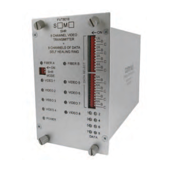
Page 2: Front Panel
INSTALLATION AND OPERATION MANUAL FVT/FVR8018SHR FIGURE 1 – FVT/FVR8018SHR TRANSMITTER AND RECEIVER MULTIMODE OR SINGLE MODE OPTICAL FIBER (Depending on Model) BLACK BLACK WITH WHITE STRIPE Power Supply: Surface Mount: 8–15 VDC @ 3W Rack Mount: From Rack FIGURE 2 – FVT8018SHR TRANSMITTER FIGURE 3 –... - Page 3 INSTALLATION AND OPERATION MANUAL FVT/FVR8018SHR FIGURE 4 – DATA CONNECTIONS See Figure 6 for Switch Positions Customer Customer FVT8018SHR Equipment Equipment FVR8018SHR Data Transmit DIN(–) DOUT(–) Data Receive RS232 Data Receive DOUT(–) DIN(–) Data Transmit Signal Ground Signal Ground Data Out (+) DIN(+) DOUT(+) Data In (+)
- Page 4 INSTALLATION AND OPERATION MANUAL FVT/FVR8018SHR FIGURE 5 – RJ45 BREAK-OUT 5 pc. Factory Supplied INS_FVT/FVR8018SHR_REVA 11/14/11 TEcH SUPPORT: 1.888.678.9427 PAGE 4...
- Page 5 INSTALLATION AND OPERATION MANUAL FVT/FVR8018SHR FIGURE 6 – DATA SWITCH POSITIONS The mode for each data channel is configured using a pair of switches on the front panel of the unit. Switch FIGURE 7 – SWITCH SETTINGS A Ports - Data Channels 1-4 B Ports - Data Channels 5-8 RS232 RS485 (2W)
- Page 6 FVT/FVR8018SHR FIGURE 8 – FIBER CONNECTIONS Many ring configurations are possible, including the addition of other Video/Data units in the ComNet SHR Product Line. Note that Optic A is always connected to Optic B on the next unit. Self Healing Ring:...
- Page 7 INSTALLATION AND OPERATION MANUAL FVT/FVR8018SHR FIGURE 9 – SHR SWITCH POSITIONS SHR Switch 2 can disable the Remote Fault locator (RFl) feature of the oPTIC DcH1/SHR Switch Resulting configuration A and oPTIC b lEds as described in Figure 10. For self-healing ring topologies, this switch would normally be turned oFF at every unit in the system so that disable Remote Fault locator (RFl) feature the RFl is enabled.
- Page 8 INSTALLATION AND OPERATION MANUAL FVT/FVR8018SHR FIGURE 11 – EXAMPLE SYSTEM IN LINEAR TOPOLOGY The figure below shows a system with FVT/FVR1010SHR units connected in a linear topology. The system demonstrates a video distribution application. A single video input is transmitted by a FVT1010SHR over fiber optic cable to three daisy-chained FVR1010SHR units. The last unit in the chain is connected to an audible alarm to indicate faults.
- Page 9 FIGURE 12 – EXAMPLE SYSTEM IN SELF-HEALING RING The figure below shows a system of four FVT1010SHR units, a FVT4014SHR unit and a FVR8018SHR unit connected as a self-healing ring. Eight channels of video enter the system at the five transmitter units and are sent to the video receiver and are displayed on a bank of monitors.
- Page 10 FVT1010SHR FVT1010SHR Unit 1 Unit 2 Unit 3 Unit 4 FIBER BREAK FVT4014SHR FVR8018SHR Unit 5 Unit 6 VIDEO IN VIDEO OUT 1 – 8 1 – 4 (e.g., Bank of Monitors) because the system is connected as a self-healing ring, all eight channels of video will still be displayed even after the fiber break. All of the units in the system will indicate the location of the fault using their oPTIC lEds as described in the table below.
-
Page 11: Installation Considerations
8 TURNBERRy PARK ROAD | GILDERSOME | MORLEy | LEEDS, UK LS27 7LE T: +44 (0)113 307 6400 | F: +44 (0)113 253 7462 | INFO-EUROPE@cOMNET.NET INS_FVT/FVR8018SHR_REVA 11/14/11 © 2011 Communications Networks Corporation. All Rights Reserved. “ComNet” and the “ComNet logo” are registered trademarks of Communication Networks, llC. PAGE 11...
Need help?
Do you have a question about the FVT4014SHR and is the answer not in the manual?
Questions and answers