
Related Manuals for Rose electronics UC1-1X16U


Summary of Contents for Rose electronics UC1-1X16U
- Page 1 UltraConsole UNIVERSAL MULTI-PLATFORM KVM AND SERIAL SWITCH Installation and Operations 10707 Stancliff Road Houston, Texas 77099 UltraConsole Manual Phone (281) 933-7673 WWW.ROSE.COM...
-
Page 2: Limited Warranty
Limited Warranty service may be obtained by delivering this Unit during the one-year warranty period to Rose Electronics or an authorized repair center providing a proof of purchase date. If this Unit is delivered by mail, you agree to insure the Unit or assume the risk of loss or damage in transit, to prepay shipping charges to the warranty service location, and to use the original shipping container or its equivalent. -
Page 3: European Union Declaration Of Conformity
FCC/IC STATEMENTS, EU DECLARATION OF CONFORMITY FEDERAL COMMUNICATIONS COMMISSION AND INDUSTRY RADIO-FREQUENCY INTERFERENCE STATEMENTS This equipment generates, uses, and can radiate radio frequency energy and if not installed and used properly, that is, in strict accordance with the manufacturer’s instructions, may cause interference to radio communication. -
Page 4: Table Of Contents
TABLE OF CONTENTS Contents Disclaimer... 1 About this manual ... 1 Introduction... 1 Features... 2 UltraConsole... 5 Models ... 5 System Overview... 6 Site planning... 10 Switch Installation – Single Unit ... 11 Switch Installation – Multiple units – “BUS” topology... 14 Switch Installation –... - Page 5 Figures Figure 1. Expansion card...8 Figure 2. Single Unit configuration ...11 Figure 3. Bus configuration...14 Figure 4. Ring configuration ...19 Figure 5. Main configuration menu...23 Figure 6. Configure system menu ...24 Figure 7. Configure computer menu...28 Figure 8. Configure KVM menu ...30 Figure 9.
-
Page 7: Disclaimer
This manual covers the installation and operations of the UltraConsole switches. Introduction Thank you for choosing the Rose Electronics keyboard-video-mouse switch. The UltraConsole switch is the result of Rose Electronics commitment to providing continued state-of-the-art switching solutions for today’s demanding workplace. The... -
Page 8: Features
Rose Electronics UltraConsole switches are designed to meet your switching needs, whatever your system demands are, two computers or hundreds. All models offer standard features that allow for easy, secure, and complete access to as many as 1,000 computers from a single user KVM station. - Page 9 Mouse Standard PS/2, PS/2 wheel, Serial (2 or 3 button), USB, Sun, Apple ADB* * Requires use of Rose Translator: CNV-MACPS and a Rose cable. Some MAC start-up options are not available using a translator. ULTRACONSOLE USERS MANUAL KVM compatibility...
- Page 10 Electronics or your reseller, so the discrepancy can be quickly resolved. Rose Electronics web site Visit our web site at www.rose.com for additional information on the UltraConsole switch and other products offered by Rose Electronics that are designed for data center applications, classroom environments, and many other applications.
-
Page 11: Ultraconsole
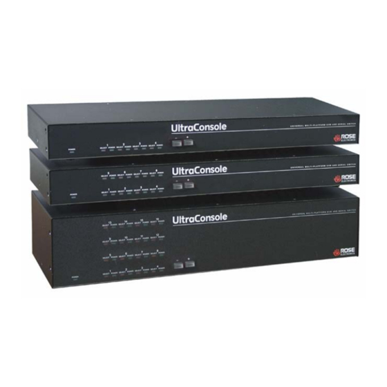
* /E option indicates an expansion card installed Connector ULTRACONSOLE USERS MANUAL Description IEC320 power connector Expansion connectors (DB15M/F) CPU / KVM connectors (DB25F) Serial connector (RJ12 – 6 pin) UltraConsole Models Model number UC1-1X4U/E* UC2-1X4U/E* UC1-1X8U/E* UC2-1x8U/E* UC1-1X16U/E* UC2-1x16U/E... -
Page 12: System Overview
Note: When using a PS/2 keyboard, the PS/2 keyboard must be capable of communicating in Mode 2 and Mode 3 if the CPU’s are PC Mode 3, USB, SUN, or a Rose Translator is used in conjunction with an Apple computer. - Page 13 Computers The UltraConsole can connect to PC’s, Unix systems, Sun systems, and USB. Apple ADB computers can be connected using a Rose translator. The CPU connectors on all UltraConsole models are DB25F. Each connected computer uses a CPU adapter cable compatible with the computer’s keyboard, monitor, and mouse ports.
-
Page 14: Figure 1. Expansion Card
OVERVIEW If an expansion card is permanently removed, a terminator and cover plate must be installed. Figure 1. Expansion card To remove the expansion card and install/remove jumper JP1: 1. Remove power from the UltraConsole switch. 2. Remove any expansion cables. 3. - Page 15 Cabling A KVM station, computers and servers are easily connected to the UltraConsole with the proper cables. Provide adequate strain relief for the CPU, KVM, and expansion cables to relieve excess tension on the connectors. Avoid routing cables close to fluorescent lights, air compressors, high voltage power sources and machinery that may create electrical noise or interference that may interfere with the operation of the UltraConsole.
-
Page 16: Site Planning
Using shorter cables keeps the video noise to a minimum and reduces installation costs. Provide proper strain relief for all cables. The UltraConsole can be rack mounted with Rose Electronics rack mount kit (see Appendix J & K). Another option that makes for a clutter free installation is the Rose Electronics RackView™. -
Page 17: Switch Installation - Single Unit
INSTALLATION Switch Installation – Single Unit Please refer to the safety section before installation The basic installation of a single UltraConsole switch is an easy and straightforward procedure. Perform the below steps for all computers that will be connected. It is recommended that all computers be powered off. - Page 18 The default keyboard type is PC mode 2, and the default mouse type is PS/2. If the computer being connected, with power applied, uses a PC2 keyboard and PS/2 mouse, no pre-configuration is needed. If not, pre-configure the keyboard and mouse types for that CPU port before connecting the computer (steps 4a-4e).
- Page 19 6. Verify that the keyboard, video, and mouse on the connected computer function properly before proceeding. 7. Switch the KVM station to the next sequential CPU port (step 3) and perform steps 4-6 for the remaining computers. When all computers are connected and operating properly, change the “Maximum computers”...
-
Page 20: Switch Installation - Multiple Units - "Bus" Topology
Switch Installation – Multiple units – “BUS” topology A “BUS” configuration is usually used when the user is connected to the KVM ports on Unit #1. In a “BUS” configuration, (Figure 3) the video path is from the last Unit in the configuration to the first Unit (“OUT” to “IN”). - Page 21 To start, identify the following prior to installation: 1. Which UltraConsole will be #1, #2, and so on 2. Which computer will be #1, #2, and so on 3. Which computers do not use a PC2 keyboard or a PS/2 mouse 4.
- Page 22 e. Next, select “Starting computer number” and press [Enter]. An input box will display for a new starting computer number. Enter the correct “Starting computer” number for this Unit (See page 15) and press [Enter]. Press the “Esc” key to return to the “Main menu”. g.
- Page 23 7. Apply power to the next unit to bus in, then connect an expansion cable (IN THIS ORDER); From: Unit #2’s “OUT” expansion card connector To: Unit #1’s “IN” expansion card connector. (Connecting the expansion cable from the “IN” connector first to the “OUT”...
- Page 24 14. Make sure all UltraConsole switches have power applied and a KVM station is connected to Unit #1. 15. Switch the KVM station to CPU port # “x” (starting with x=1) by pressing and releasing the left control [Ctrl] key and within 2 seconds, type in 1 (or the CPU port # being configured) and press [Enter].
-
Page 25: Switch Installation - Multiple Units - "Ring" Topology
Switch Installation – Multiple units – “RING” topology A “RING” configuration is usually used when a user needs access to all computers from different KVM stations. In a “RING” configuration, a user on any KVM station in the ring can access all the computers in the system. - Page 26 All Units must be equipped with an expansion card. To begin setting up your system in a “RING” configuration, perform steps 1 – 13 as outlined in setting up a “BUS” configuration. When doing this, keep in mind that the “OUT” expansion card connector on the first Unit will be connected with an expansion cable to the “IN”...
- Page 27 Boot the computer if power is not applied. You should see the boot up sequence on the KVM monitor. If the computer was connected to a pre-configured CPU port with power applied, you should see that computers video. Verify that the keyboard, video, and mouse on the connected computer function properly before proceeding.
-
Page 28: Configuration Menus
CONFIGURATION MENUS Menu structure Use only the numeric keys above the keyboard. The numeric keypad will not work for entering numbers. System System settings Configure password Starting computer number Mouse Maximum computers Keyboard settings PC keyboard rate PC Keyboard delay Sun keyboard language Appearance Menu color scheme... -
Page 29: Main Menu
Main Menu UltraConsole version MX22D Rose Electronics Copyright 1990-2003 Main Menu Configure System Computer User Profile Group Language Status Save Exit Use up/down arrow keys to choose selection then press the Enter key or the Escape key to exit Configure password,box number,keyboards settings,appearance Figure 5. -
Page 30: Configure System Menu
Configure System menu Configure system System settings Configure password Starting computer number Maximum computers Keyboard settings PC keyboard rate (chars/sec) PC keyboard delay Sun keyboard language Appearance Menu color scheme Screen saver Screen saver time (seconds) Background color Text color Position Fadeout (seconds) Password to configure unit... - Page 31 Starting computer number (Default: 1) The “Starting computer number” defines to the system, the first CPU port number for a particular UltraConsole switch that is configured in an expanded topology. (See page 15) Switch #1’s starting computer number is always 1. Switch #2’s number is the total CPU ports on Unit #1 plus 1.
- Page 32 Sun keyboard language (Default: US) Determines the response to a Sun computer’s query for the keyboard language type used. To change the Sun keyboard language type, select it and press [Enter]. A selection box will display showing the supported Sun language choices. Use the up/down arrow keys to select the desired language and press [Enter].
- Page 33 Screen saver time (seconds) (Default: 1800 seconds) Determines the period of keyboard or mouse inactivity before activating the screen saver. To change the screen saver time, select it from the menu and press [Enter]. An input box will display to enter a new screen saver time.
-
Page 34: Configure Computer Menu
Configure Computer menu Configure computer Computer name Computer 2 Computer 3 Computer 4 Computer 5 Computer 6 Computer 7 Computer 8 Computer 9 Computer 10 Computer 11 Computer 12 Computer 13 Computer 14 Computer 15 Computer 16 Computer Use page up and page down keys to configure more computers Name of computer, up to 16 characters Figure 7. - Page 35 To change the keyboard type for a selected computer or configure the CPU port for a serial device, use the up/down arrow keys to select the computer whose keyboard needs changing. Use the right arrow key to select the keyboard field and press [Enter]. A selection box will display listing the supported keyboard types and serial support options.
-
Page 36: Configure Kvm Menu
Configure KVM menu Configure KVM KVM name KVM station 1 Name of keyboard-video-mouse station (KVM) up to 16 characters Figure 8. Configure KVM menu The “Configure KVM” menu allows you to change the KVM name, resolution, start, and user parameters. The ID column indicates the physical location (port) the KVM is connected to. - Page 37 Resolution (Default: 640x480@60Hz) Selects the resolution and scan rate of the on-screen display when no attached computer video is present. If a computer video is shown, the detected video resolution from the connected computer is used. To change the resolution select the resolution field and press [Enter]. A list of supported resolutions will display.
-
Page 38: Configure User Menu
The configure user, profile, and group features provide a flexible and reliable security set-up for your system. Configure User menu Configure User User name Password User 1 * * * * * * * * User 2 * * * * * * * * User 3 * * * * * * * * User 4... - Page 39 Password (Default: no password) This field assigns a unique password to a selected user. Any KVM station that has “Login” enabled, the user must enter their username and password to gain access to the KVM station. To assign or change a user password, select the user, then the password field and press [Enter].
-
Page 40: Configure Profile Menu
Configure Profile menu Configure Profile Name Access Profil 1 Group 1 Profil 2 Group 2 Profil 3 Group 3 Profil 4 Group 4 Profil 5 Group 5 Profil 6 Group 6 Profil 7 Group 7 Profil 8 Group 8 Profil 9 Group 9 Profil10 Group10... - Page 41 Mode (Default: Share) Assigns 1 of 4 modes to a profile. To change the mode, select the profile to change the mode, then select the mode to change and press [Enter]. A selection box will display. Select the mode needed and press [Enter].
- Page 42 Logout (Default: 240 minutes) This setting disconnects and logs out a user after the set period of no keyboard or mouse activity. To change the logout value, select the profile, then the logout time to change and press [Enter]. An input box will display.
-
Page 43: Configure Group Menu
Configure Group menu Configure Group Computer 1 Computer 2 Computer 3 Computer 4 Computer 5 Computer 6 Computer 7 Computer 8 Computer 9 Computer 10 Computer 11 Computer 12 Computer 13 Computer 14 Computer 15 Computer 16 Computer SPACE BAR adds/removes computer from group Enter renames group Page up/down more computers + computer belongs to group Figure 11. -
Page 44: System Status Display
Configure Language UltraConsole version MX22D Rose Electronics Copyright 1990-2003 Main Menu Configure System Computer User Profile Group Language Status Save Exit Use up/down arrow keys to choose selection then press the Enter key or the Escape key to exit Language which will be displayed on the screen Figure 12. -
Page 45: Figure 12. System Status Display
System Status Computers Power 9-12 13-16 17-20 21-24 25-28 29-32 33-36 37-40 41-44 45-48 49-52 53-56 57-60 61-64 Pos=Card position | Ver=Program version | KVM=PC/Sun/None CPU power Figure 13. System status display The system status display is a very powerful and useful tool when monitoring, expanding, troubleshooting, or reconfiguring a system. -
Page 46: Save Menu
User Displays the users name that is currently accessing the system. Status Displays the most recent connect or disconnect status for the KVM station on this CPU card. Save menu UltraConsole version MX22D Rose Electronics Copyright 1990-2003 ULTRACONSOLE USERS MANUAL... -
Page 47: Figure 13. Save Menu
Main Menu Configure System Computer User Profile Group Language Status Save Exit Use up/down arrow keys to choose selection then press the Enter key or the Escape key to exit Configure password,box number,keyboards settings,appearance Figure 14. Save menu When changes are made to any configuration, they must be saved in flash memory to insure that the changes will be active after a power cycle. -
Page 48: Operation
OPERATION User operating instructions The following instructions apply to all UltraConsole switches. This section explains the operating functions of the on-screen displays, the login procedure, connect procedure and other commands needed to easily use the UltraConsole switch and its capabilities. To start using your UltraConsole switch, you first need to become familiar with the keyboard commands. -
Page 49: Figure 14. Login Screen
Keyboard commands (continued) Command Key Sequence Send Null Byte [Ctrl] N Reset Mouse [Ctrl] O (not zero) (NT or Unix systems only) Start Scan [Ctrl] S Stop Scan [Ctrl] X Table 1. Keyboard commands When you first start using a KVM station, it may require you to login. If the KVM station requires a login, the login box, shown in Figure 15, will display. -
Page 50: Figure 15. Computer Select Menu
To access the “Computer select” menu, press and release the left [Ctrl] key, then press the [Esc] key. The computer select menu shown in Figure 16 will display. Use the up/down arrow keys and the page up/page down keys and select the computer to switch to and press [Enter]. -
Page 51: Figure 16. Connection Successful Message
Status Mail server Connection successful to NT Server On Admin Share mode Figure 17. Connection successful message Status Control Room 5 Connection failed to Mail server On Richard Not in access group Figure 18. Connection failed message Status Mail server Disconnected from Payroll On Sharon... -
Page 52: Serial Port Usage (Rs232)
A serial cable (RJ12, 6-wire connector and an appropriate adapter for the computer’s serial port). The serial cable and adapter are provided with each switch (Rose part number KIT-ATRX) A dedicated computer, Notebook computer with a serial port, or a display terminal. -
Page 53: Starting A Serial Communication Session
Click “OK” when all values have been entered. The HyperTerminal dialog box will display and information can be exchanged with the UltraConsole switch properly. You can save this setup so the next time its needed, you can select the ICON with the name you gave it and these settings will already be established. -
Page 54: Serial Menu Options
UC Serial option - HyperTerminal File Edit View Call Transfer Help Serial options menu Change starting computer number … 1 Change the serial port baud rate Receive new main program or kernel from serial port (this card only) Send this unit’s main program to other units Send this unit’s kernel to other units Reset configuration data to factory defaults (this card only) Save changes made in 1 and 2 (this card only) - Page 55 (This card only) When new main or kernel programs are available, they can be obtained from Rose Electronics or downloaded from our web site at www.rose.com. The diagnostic screen that is displayed when the UltraConsole switch is first turned on shows the Kernel and main program version that is presently installed.
- Page 56 You may receive one of the following errors during the file transfer function: checksum error, record error, or data error. These messages are followed by: Receive failed Try again Y/N These error messages may be caused by any of the following items: Corrupted firmware upgrade file.
- Page 57 When complete, the system returns you to the serial options menu. Wait at least 15 seconds before restarting the UltraConsole after choosing option 4 or 5 for the program to propagate to the other cards in the system. Option 6. Reset to Factory Defaults (This CPU card only) NOTE: Before resetting any CPU card to factory defaults, note the starting computer number listed on the Serial menu, Option 1.
-
Page 58: Serial Device Support
SERIAL DEVICE SUPPORT Serial device support The serial feature allows you to connect a KVM station to a serial device such as the serial port on a Unix or Sun computer, a communication device, or any device with a serial port. The serial device is connected to the DB25F CPU port on the UltraConsole with a serial cable (See Appendix C for serial cable part numbers). -
Page 59: Figure 20. Serial Support
Configure Computer Computer name Computer Computer Computer Computer Computer Computer Computer Computer Computer Computer Computer Computer Computer Computer Computer Computer Use page up and page down keys to configure more computers, Type of computer, for PCs this is the computer’s keyboard mode Figure 21. - Page 60 The page up and page down keys allow you to scroll the incoming pages in the four page scroll buffer. The F12 key clears the screen. ULTRACONSOLE USERS MANUAL...
-
Page 61: Service Information
Technical Support hours are from: 8:00 am to 6:00 pm CST (USA), Monday through Friday. Please report any malfunctions in the operation of this Unit or any discrepancies in this manual to the Rose Electronics Technical Support Department. ULTRACONSOLE USERS MANUAL... -
Page 62: Safety
SAFETY Safety This UltraConsole switch has been tested for conformance to safety regulations and requirements, and has been certified for international use. Like all electronic equipment, the UltraConsole switch should be used with care. To protect yourself from possible injury and to minimize the risk of damage to this Unit, read and follow these safety instructions. -
Page 63: Safety And Emc Regulatory Statements
Safety and EMC Regulatory Statements Safety Information Documentation reference symbol. If the product is marked with this symbol, refer to the product documentation to get more information about the product. WARNING hazard that can cause injury or death. CAUTION A CAUTION in the manual denotes a hazard that can damage equipment. - Page 64 Safety and EMC Regulatory Statements Informations concernant la sécurité Symbole de référence à la documentation. Si le produit est marqué de ce symbole, reportez-vous à la documentation du produit afin d’obtenir des informations plus détaillées. WARNING indique un danger susceptible d’entraîner des dommages corporels ou la mort.
-
Page 65: Troubleshooting
TROUBLESHOOTING Troubleshooting Computer does not boot, keyboard or mouse error received CPU cable is loose. Re-seat cable and hit F1 to continue or reboot computer. Wrong cable plugged in. Keyboard and mouse cables reversed. CPU cable is defective. Try using CPU cable from another computer. - Page 66 Can’t access all functions of mouse If Microsoft BallPoint mouse, get latest Microsoft mouse driver. Mouse does not move The UltraConsole turned off after or not attached when computer booted or application began using mouse. Exit and re-enter application using mouse or issue reset command. PS/2 mouse was not attached when the UltraConsole powered up or has been detached and reattached.
-
Page 67: Appendices Appendix A. Initial Factory Default Settings
APPENDICES Appendix A. Initial factory default settings Function Setting System Password Starting Computer Number Maximum Computer PC keyboard rate (chars/sec) 20 PC keyboard delay Sun keyboard language Menu Color Scheme Screen saver Screen saver time (seconds) 1200 seconds Background color Text color Fadeout Computer Computer name... -
Page 68: Appendix B. General Specifications
Appendix B. General specifications Specification Dimensions 16.7 x 4.85 x 1.75 in. 42.4 x 12.3 x 4.4 cm. Weight 4lb. / 1.8 kg. Power Auto-switching 100 – 240 VAC Input - 100-240 VAC Output - +5Vdc, 2.0A Output - +12Vdc. 0.2A Power supply is installed internally and input power is provided through a... -
Page 69: Appendix C. Parts And Cables
CNV-DECPS Rack Mount Kits RM-UB19 / 23 / 24 RM-UC19 / 23 / 24 nnn = length in feet * Requires Rose translator – CNV-MACPS ULTRACONSOLE USERS MANUAL Description Coax – VGA/PS2 HD15/MD6 Kbd/Mouse Standard – VGA/PS2 HD15/MD6 Kbd/Mouse Coax – Sun HD15 video /MD8 kbd-mouse Coax –... -
Page 70: Appendix D. Status Connect / Failure Reason Summary
Appendix D. Status Connect / Failure Reason Summary Reason Can’t Find Computer No Response Not in Access Group Out of Range Unknown Computer Unknown Reason Description Unable to communicate to the computer that’s being connected to. Communications error. A user profile specifies a group without access to this computer. -
Page 71: Appendix E. Disconnect Status Reasons
Appendix E. Disconnect Status Reasons Reason No Response Private Mode Cancel User disconnected Timed Out Unknown Computer Unknown Reason User Request Video Path Cancel ULTRACONSOLE USERS MANUAL Description Disconnect communication error. from computer because another user has connected in Private Mode. Keyboard or mouse has not been used for the period specified in... -
Page 72: Appendix F. Kvm Placement / Conflicts
Appendix F. KVM placement / conflicts It is possible, in an expanded system with multiple UltraConsole switches, to connect additional KVM stations to other UltraConsole units in the system. This allows access to the computers from multiple locations. When doing this, all KVM ports share the same video path from switch to switch. -
Page 73: Appendix G. Password Jumper
Appendix G. Password jumper If the configuration password is ever forgotten, the UltraConsole switch has a special “Password” reset jumper on the CPU card. This jumper is labeled JP31 on all models. To use this jumper to bypass the password, perform the following: 1. -
Page 74: Appendix H. Diagnostic Check / Error Messages
Appendix H. Diagnostic check / error messages The power on diagnostic screen that appears when the UltraConsole switch is first turned on, checks the switch and provides the information shown on the screen. Welcome to UltraConsole Power on diagnostics Kernel version Overlay version Kernel program Static ram... - Page 75 Configuration Board number Communication ID Indicates network board number (1-256) of the Communication Local CPU ports Program version Main program PC Keyboard detected PS2 mouse detected ULTRACONSOLE USERS MANUAL Reports the results of checksum calculations of configuration memory. Any results other than GOOD terminates the diagnostic sequence, indicating a hardware failure.
- Page 76 Kernel halt error messages Message BAD Address = nn Resetting to factory defaults Unit Halted Kernel is bad, load new kernel through serial port. Checksum error Kernel memory is corrupt, hardware failure. A memory error is detected during a read from configuration memory.
-
Page 77: Appendix I. Video Distance Table
Letters shows the cable type, and a number that refers to the quality of the video, as described below. Rose Electronics does not recommend systems where the video quality is 1 or 2. There are further capabilities, not listed here, that will send the higher resolution video longer distances. -
Page 78: Appendix J. Rack Mount
Appendix J. Rack mount The UltraConsole can be mounted in a rack using the Rackmount kits from Rose Electronics. The optional rack mount kit includes the following items: Two black anodized mounting brackets. Four 6-32 x 3/8” flat head mounting screws. -
Page 79: Appendix K. Rack Mount Illustration
Appendix K. Rack mount illustration ULTRACONSOLE USERS MANUAL... - Page 80 10707 Stancliff Road Phone: (281) 933-7673 Houston, Texas 77099 WWW.ROSE.COM...
Need help?
Do you have a question about the UC1-1X16U and is the answer not in the manual?
Questions and answers