Table of Contents
Advertisement
Quick Links
Advertisement
Table of Contents

Related Manuals for FISCHER ECO-LINE FT80


Summary of Contents for FISCHER ECO-LINE FT80
- Page 1 Modbus Operating manual FT80 Humidity and temperature measuring device ECO-LINE ®...
- Page 2 Great care was taken when compiling the texts and illustrations; Nevertheless, errors cannot be ruled out. The company FISCHER Mess- und Regeltechnik GmbH will not accept any legal responsibility or liability for this.
-
Page 3: Table Of Contents
FISCHER Mess- und Regeltechnik GmbH Table of contents Table of contents 1 Safety instructions......................4 1.1 General........................... 1.2 Personnel Qualification ......................1.3 Risks due to Non-Observance of Safety Instructions............. 1.4 Safety Instructions for the Operating Company and the Operator ......... -
Page 4: Safety Instructions
1 | Safety instructions FISCHER Mess- und Regeltechnik GmbH 1 Safety instructions 1.1 General This operating manual contains basic instructions for the installation, operation and maintenance of the device that must be followed without fail. It must be read by the installer, the operator and the responsible specialist personnel be- fore installing and commissioning the device. -
Page 5: Safe Working Practices For Maintenance And Installation Work
FISCHER Mess- und Regeltechnik GmbH Safety instructions | 1 1.7 Safe working practices for maintenance and installation work The safety instructions given in this operating manual, any nationally applicable regulations on accident prevention and any of the operating company's internal work, operating and safety guidelines must be observed. -
Page 6: Product And Functional Description
2 | Product and functional description FISCHER Mess- und Regeltechnik GmbH 2 Product and functional description 2.1 Delivery scope • Humidity and temperature measuring device FT80 • FF80 humidity and temperature sensor • Locking screw (included in the device) • Mounting flange for duct sensor version •... -
Page 7: Device Versions
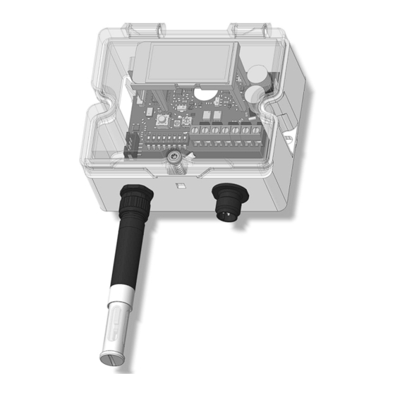
FISCHER Mess- und Regeltechnik GmbH Product and functional description | 2 2.5 Device versions Version with display Version without display Fig. 2: Device versions 2.5.1 Process connection NOTICE! The sensor can also be mounted remotely with an M12 cable. Humidity and temperature measuring device... - Page 8 2 | Product and functional description FISCHER Mess- und Regeltechnik GmbH 2.5.2 Electrical connection Option A: Option B: Cable screw connection M12 plug connection Cable screw connection M16 x 1.5 5-pin Fig. 4: Electric connections 2.5.3 Type plate D-32107 Bad Salzuflen...
-
Page 9: Installation
FISCHER Mess- und Regeltechnik GmbH Installation | 3 3 Installation 3.1 General The device is designed for installation on assembly plates or wall surfaces. For this purpose, the device has two fastening lugs integrated into the side. The at- tachment screws are not included in the delivery. -
Page 10: Mechanical Installation And Mounting
3 | Installation FISCHER Mess- und Regeltechnik GmbH (c) Mounting the screw plug The installation of the locking screw ensures that the release is blocked and the cover is held in position. It is a self-tapping screw for polycarbonate. During installation (1), a screw-in torque [M ] of maximum 1.2 Nm is required to... - Page 11 FISCHER Mess- und Regeltechnik GmbH Installation | 3 3.2.1 Installation of the sensor It is possible to connect the humidity and temperature sensor (FF80) to the FT80 with an M12 cable and to mount it separately from the device. For this purpose, the corresponding connection cables and a mounting clip for installa- tion on flat surfaces and pipes are available as accessories.
-
Page 12: Electrical Connection
3 | Installation FISCHER Mess- und Regeltechnik GmbH 3.3 Electrical connection • By authorized and qualified specialized personnel only. • When the device is connected, national and international electrotechnical regulations must be observed. • Disconnect the system from the mains before electrically connecting the device. -
Page 13: Start-Up
FISCHER Mess- und Regeltechnik GmbH Start-up | 4 4 Start-up 4.1 General All electrical supply, operating and measuring lines, and the pressure connec- tions must have been correctly installed before commissioning. All supply lines are arranged so that there are no mechanical forces acting on the device. - Page 14 4 | Start-up FISCHER Mess- und Regeltechnik GmbH 4.3.1.1 Measuring range 4.3.1.1.1 Temperature (channel 1) °F °C 5 6 7 Fig. 16: Unit of temperature -20 ... +80 °C 0 ... +200 °F 5 6 7 0 ... +50 °C +40 ... +140 °F -40 ...
- Page 15 FISCHER Mess- und Regeltechnik GmbH Start-up | 4 4.3.1.2 Output signal The switch position always affects both analogue outputs. 0 ... 20 mA 4 ... 20 mA 0 ... 10 V 2 ... 10 V Fig. 20: Analogue output 4.3.1.3 Description of functions The DIP switch is used to configure the two measuring channels and the output signal.
- Page 16 4 | Start-up FISCHER Mess- und Regeltechnik GmbH 4.3.2 Device with Modbus NOTICE! In this section you will learn how to configure a Modbus device. Further information can be found in the Modbus manual. Status LED Bus configuration DIP switches DIP switch...
- Page 17 FISCHER Mess- und Regeltechnik GmbH Start-up | 4 4.3.2.1 Modbus address NOTICE! Address 0 is reserved for the broadcast. For this reason, a decimal 1 is added to each set address. S1 S2 S3 S4 S5 S6 S7 Σ Address Binary...
- Page 18 4 | Start-up FISCHER Mess- und Regeltechnik GmbH 4.3.2.3 Description of functions DIP switches The Modbus is configured with the DIP switch. There are two settings areas. They are divided into interface and address con- figurations. Switch S8 allows you to switch between the two setting areas.
-
Page 19: Servicing
FISCHER Mess- und Regeltechnik GmbH Servicing | 5 5 Servicing 5.1 Maintenance The instrument is maintenance-free. We recommend the following regular in- spection to guarantee reliable operation and a long service life: • Check the function in combination with downstream components. -
Page 20: Technical Data
6 | Technical data FISCHER Mess- und Regeltechnik GmbH 6 Technical data 6.1 General Type designation FT80 Measuring variable Humidity Temperature Measurement Humidity Capacitive principle Temperature Band gap Remote sensor 5 m max. cable length (between sensor and device) Installation position... -
Page 21: Measuring Accuracy
FISCHER Mess- und Regeltechnik GmbH Technical data | 6 6.4 Measuring accuracy 6.4.1 Humidity ΔrF [% rH] ±6 Max. measurement error ±5 Typ. measurement error ±4 ±3 ±2 ±1 ±0 [% rH] Fig. 25: Measurement error at 25 °C Measurement deviation ±... -
Page 22: Digital Interfaces
6 | Technical data FISCHER Mess- und Regeltechnik GmbH 6.5 Digital interfaces Modbus RTU interface interface RS 485 Report Modbus RTU Modbus specification Application Protocol Specification V1.1b3 (April 26, 2012) Address 1 … 128 Baud rate 2400 … 115200 Baud... -
Page 23: Construction Design
FISCHER Mess- und Regeltechnik GmbH Technical data | 6 6.9 Construction design Electrical 3-conductor Modbus RTU connection Cable screw connection PCB terminal PCB terminal M16x1.5 No. of pins 5 No. of pins 5 M12 plug connection 5-pin 5-pin male male... - Page 24 6 | Technical data FISCHER Mess- und Regeltechnik GmbH Design with M12 plug connection M12 x 1 M12 plug Remote sensor Cable tie lead-through Fig. 27: Mounting clip Duct sensor Mounting flange (stainless steel) Fig. 28: Duct sensor (standard) 24/32 BA_EN_FT80...
- Page 25 FISCHER Mess- und Regeltechnik GmbH Technical data | 6 Fig. 29: Stainless steel mounting flange (12.2 mm) Sensor extension Mounting flange (plastic) Fig. 30: Sensor extension BA_EN_FT80 25/32...
- Page 26 6 | Technical data FISCHER Mess- und Regeltechnik GmbH Fig. 31: Plastic mounting flange (16 mm) 26/32 BA_EN_FT80...
-
Page 27: Order Codes
FISCHER Mess- und Regeltechnik GmbH Order codes | 7 7 Order codes Code no. 13 14 Type Measurement range: [3.4] Measuring range Sensor Humidity 0...100 % rH Plastic with stainless steel filter Temperature -20 ... +70 °C remote sensor -40 ... +95 °C Humidity 0...100 % rH... -
Page 28: Accessories
7 | Order codes FISCHER Mess- und Regeltechnik GmbH 7.1 Accessories M12 connection cables Call sign No. of Length Order no. pins PUR connection cable with M12 coupling, 5-pin 06401995 A-coded (Modbus) 06401996 10 m 06401573 Connection cables for FF80 humidity and temperature sensor Call sign No. -
Page 29: Annex
FISCHER Mess- und Regeltechnik GmbH Annex | 8 8 Annex Fig. 32: CE_DE_FT80 BA_EN_FT80 29/32... - Page 30 8 | Annex FISCHER Mess- und Regeltechnik GmbH Fig. 33: UKCA_DE_FT80 30/32 BA_EN_FT80...
- Page 31 FISCHER Mess- und Regeltechnik GmbH Notes BA_EN_FT80 31/32...
- Page 32 Mess- und Regeltechnik GmbH Bielefelder Str. 37a D-32107 Bad Salzuflen Tel. +49 5222 974-0 Fax +49 5222 7170 www.fischermesstechnik.de info@fischermesstechnik.de Technische Änderungen vorbehalten. Subject to technical changes. Sous réserve de modifications techniques.
Need help?
Do you have a question about the ECO-LINE FT80 and is the answer not in the manual?
Questions and answers