Table of Contents

Related Manuals for FISCHER DS21xxxH series


Summary of Contents for FISCHER DS21xxxH series
- Page 1 Operating Manual DS21 ... H Differential pressure measuring and switching device for explosive areas Flow guard in heat transfer oil systems in compliance with DIN 32727 and hot water systems according to VdTÜV Information sheet "Flow 100"...
- Page 2 | Masthead FISCHER Mess‐ und Regeltechnik GmbH Masthead Manufacturer: FISCHER Mess und Regeltechnik GmbH Bielefelderstr. 37a 32107 Bad Salzuflen Telephone: +49 5222 974 0 Telefax: +49 5222 7170 eMail: info@fischermesstechnik.de web: www.fischermesstechnik.de Technical editorial team: Documentation representative: S. Richter Technical editor: R.Kleemann All rights, also those to the translation, reserved. No part of these instructions may be reproduced or processed, duplicated or distributed using electronic sys tems or any other form (print, photocopy, microfilm or another process) without the written consent of the company Fischer Mess und Regeltechnik GmbH, Bad Salzuflen. Reproduction for internal use is expressly allowed. Brand names and procedures are used for information purposes only and do not take the respective patent situation into account. Great care was taken when compiling the texts and illustrations; nevertheless, errors cannot be ruled out. The company FISCHER Mess und Regeltechnik GmbH will not accept any legal responsibility or liability for this. Subject to technical amendments. © FISCHER Mess und Regeltechnik GmbH 2014 2 / 48 BA_EN_DS21_H_ST4‐A...
-
Page 3: Table Of Contents
FISCHER Mess‐ und Regeltechnik GmbH Table of contents Table of contents 1 Safety notes .............................. 5 1.1 General.............................. 5 1.2 Personnel Qualification ........................... 5 1.3 Risks due to NonObservance of Safety Instructions................ 5 1.4 Safety Instructions for the Operating Company and the Operator ............ 5 1.5 Unauthorised Modification........................ 6 1.6 Inadmissible Modes of Operation...................... 6 1.7 Safe working practices for maintenance and installation work.............. 6 1.8 Pictogram explanation.......................... 6 2 Product and functional description...................... 7 2.1 Use as intended ............................ 7 2.2 Equipment versions.......................... 7 2.3 Function diagram............................. 9... - Page 4 Table of contents FISCHER Mess‐ und Regeltechnik GmbH 8 Attachments .............................. 33 8.1 EC Declaration of conformity........................ 33 8.2 EC declaration of conformity ATEX...................... 34 8.3 EC type testing in compliance with 97/23/EC.................. 35 8.4 Quality assurance system in compliance with 97/23/EC................ 36 8.5 ATEX Certificate............................. 37 8.6 EAC Declaration............................. 43 8.7 DIN CERTCO Certification DIN 32727:198102.................. 43 8.8 Part test current 100.......................... 44 8.9 GL Certificate ............................ 45 8.10 SIL Certificate............................ 46 BA_EN_DS21_H_ST4‐A...
-
Page 5: Safety Notes
FISCHER Mess‐ und Regeltechnik GmbH Safety notes | 1 1 Safety notes 1.1 General This operating manual contains instructions fundamental to the installation, op WARNING eration and maintenance of the device that must be observed unconditionally. It must be read by the assembler, operator and the specialized personnel in charge of the instrument before it is installed and put into operation. This operating manual is an integral part of the product and therefore needs to be kept close to the instrument in a place that is accessible at all times to the responsible personnel. The following sections, in particular instructions about the assembly, commis sioning and maintenance, contain important information, nonobservance of which could pose a threat to humans, animals, the environment and property. The instrument described in these operating instructions is designed and manu factured in line with the state of the art and good engineering practice. 1.2 Personnel Qualification The instrument may only be installed and commissioned by specialized person nel familiar with the installation, commissioning and operation of this product. Specialized personnel are persons who can assess the work they have been assigned and recognize potential dangers by virtue of their specialized training, their skills and experience and their knowledge of the pertinent standards. For explosionproof models the specialized personnel must have received spe WARNING cial training or instruction or be authorized to work with explosionproof instru ments in explosion hazard areas. 1.3 Risks due to NonObservance of Safety Instructions Nonobservance of these safety instructions, the intended use of the device or the limit values given in the technical specifications can be hazardous or cause... -
Page 6: Unauthorised Modification
1 | Safety notes FISCHER Mess‐ und Regeltechnik GmbH Repairs may be carried out by the manufacturer only. A professional single conformity inspection as per DIN EN 61010, section 1, must be carried out before the instrument can be recommissioned. This in spection must be performed at the manufacturer's location. Correct transport and storage of the instrument are required. 1.5 Unauthorised Modification Modifications of or other technical alterations to the instrument by the customer are not permitted. This also applies to replacement parts. Only the manufac turer is authorised to make any modifications or changes. 1.6 Inadmissible Modes of Operation The operational safety of this instrument can only be guaranteed if it is used as intended. The instrument model must be suitable for the medium used in the system. The limit values given in the technical data may not be exceeded. The manufacturer is not liable for damage resulting from improper or incorrect use. 1.7 Safe working practices for maintenance and installation work The safety instructions given in this operating manual, any nationally applicable regulations on accident prevention and any of the operating company's internal work, operating and safety guidelines must be observed. The operating company is responsible for ensuring that all required mainten ance, inspection and installation work is carried out by qualified specialized per sonnel. 1.8 Pictogram explanation Type and source of danger DANGER This indicates a direct dangerous situation that could lead to death or serious injury (highest danger level). -
Page 7: Product And Functional Description
FISCHER Mess‐ und Regeltechnik GmbH Product and functional description | 2 2 Product and functional description 2.1 Use as intended The unit is exclusively designed for the purpose defined by the manufacturer in the data sheet or operating instructions. The unit is suitable for operation in potentially explosive areas ▪ Zone 1 and 2 – Risk from vapours ▪ Zone 21 and 22 – Risk from dust For every application, the respective installation instructions and the conditions laid out in the section 'Use in explosive areas' must be observed. Differential pressure measuring and switching device The DS21 is a measuring and switch unit for measuring differential pressure under difficult measuring conditions such as: pressure surges, vibrations, fre quent switching and high demands on the switching output. Please contact the manufacturer before using this unit with dirty or aggressive media because the unit needs to be adapted in terms of the parts that come into contact with the media. Flow assurance The units in this series are used as flow guards in heat tranfer oil systems in compliance with DIN 32727 and hot water systems in compliance with VdTÜV information sheet 'Flow 100'. The flow guards comprise a differential pressure transducer, e.g. a measuring orifice, the differential pressure measuring and switch unit and shutoff fittings. The respective installation instructions must be observed for this application case. All units of the series DS21 satisfy these re quirements. The type tests in compliance with DIN 32 727 and VdTÜV information sheet NOTICE "Flow 100" only apply in conjunction with a differential pressure transducer, not... - Page 8 2 | Product and functional description FISCHER Mess‐ und Regeltechnik GmbH Switch panel installation NOTICE Please note that the switch points of devices with bayonet rings need to be set before mounting the control panel. When installed, the unit can no longer be opened. Please see the order code for the process connection options. 2.2.1 Pressure chamber in aluminium Pressure chamber Ground connection Pressure equalisation element Electrical connections Assembly foot Process connection Process connection differential pressure pressure Process connection rear Process connection below Switch panel installation kit Illustration 1: DS21 Pressure chamber in aluminium [ATEX] 8 / 48 BA_EN_DS21_H_ST4‐A...
-
Page 9: Function Diagram
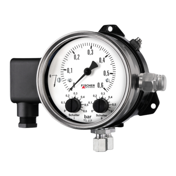
FISCHER Mess‐ und Regeltechnik GmbH Product and functional description | 2 2.2.2 Pressure chamber in stainless steel Assembly foot Illustration 2: DS21 Pressure chamber in stainless steel [ATEX] 2.2.3 Electro connection variants All unit models are suppled with a cable socket. Only the GL model is supplied with an additional 3 m long connection cable. The associated wiring diagrams are shown on the type plate and in the section 'Installation and assembly'. 2.3 Function diagram Model as differential pressure measuring and switching device Illustration 3: DS21 Function diagram differential pressure [ATEX] BA_EN_DS21_H_ST4‐A 9 / 48... -
Page 10: Design And Mode Of Operation
2 | Product and functional description FISCHER Mess‐ und Regeltechnik GmbH Model as pressure measuring and switching device Illustration 4: DS21 Function diagram pressure [ATEX] Pressure chamber Motion train Tappet Microswitch Switch point setting Measuring diaphragm Measuring springs Ground connection Closing plug 2.4 Design and mode of operation The basis for this measurement and switch unit is a sturdy nonsensitive dia phragm measuring unit that is suitable for measuring differential pressure, and over and underpressure. The unit uses the same measuring principle for all three measuring applications. In the idle position, the spring forces are equalised on both sides of the measur ing diaphragm. The pressure that is to be measured or the differential pressure creates a onesided force on the measuring diaphragm that moves the dia phragm system against the measuring range springs until the spring forces are equalised. In the case of overload, the measuring diaphragm is supported by metallic contact surfaces. A central tappet transfers the movement of the diaphragm system onto the dis play mechanism and, at the same time, onto the actuation elements of the mi croswitches. The switch points are set via the setting screws and refernec value scale. 10 / 48... -
Page 11: Installation And Assembly
FISCHER Mess‐ und Regeltechnik GmbH Installation and assembly | 3 3 Installation and assembly 3.1 General The instrument may only be installed and commissioned by specialized person nel familiar with the installation, commissioning and operation of this product. Specialized personnel are persons who can assess the work they have been assigned and recognize potential dangers by virtue of their specialized training, their skills and experience and their knowledge of the pertinent standards. If units are used in potentially explosive areas, the personnel must receive addi tional training or briefings or have a permit to work ion explosionprotected units in potentially explosive systems. 3.2 Assembly The standard unit is designed for wall mounting. This is accomplished using the rear attachment plate that acts as a mounting foot. A control panel installation set can be ordered for each unit that allowed install ation on the front of the unit. The unit can be ordered for use as a pressure, measuring and switch unit; it is designed for direct mounting. This is accomplished using a connection adapter that is either mounted bewlo th eunit or on the rear wall. Wall mounting is not possible if there is a rear connection adapter. The unit is set for vertical installation exworks. Only this installation poistion is allowed. To ensure safety during installation and maintenance, we recommend installing a suitable shutoff valve on the system. Installation regulations WARNING During installation and mounting, the applicationspecific installation guidelines in the respective approvals in the appendix must be satisfied. Falling objects WARNING... - Page 12 3 | Installation and assembly FISCHER Mess‐ und Regeltechnik GmbH ▪ Certificates and declarations: CE declaration of conformity for equipment of category 2 EC Examination Certificate 94/9/EC (TÜV 06 ATEX 2964) Zone 21 and 22 – Risk from conductive dust ▪ Order code: DS21 # # # # # # # # # # # H ▪ Identification: II 2D tb c IIIC T70 °C Db ▪ Certificates and declarations: CE declaration of conformity for equipment of category 2 EC Examination Certificate 94/9/EC (TÜV 06 ATEX 2964) 3.3.2 Authorized temperatures ▪ Permissible ambient temperature: 10 °C ≤ T ≤ 60 °C ▪ Allowed medium temperature in the differential measurement instrument: 60°C. Depending on the system, the media may reach temperatures of > 60°C. No media flows through the pressure differential lines between the pressure differ Differential ential transducer and the differential pressure measuring and switch unit. When T=60 °C pressure line...
-
Page 13: Process Connection
FISCHER Mess‐ und Regeltechnik GmbH Installation and assembly | 3 Sunlight WARNING In order to avoid additional heating, the instruments may not be exposed to dir ect sunlight during operation. Isolation WARNING The differential pressure lines may not be insulated. 3.4 Process connection ▪ By authorized and qualified specialized personnel only. ▪ The pipes need to be depressurized when the instrument is being connec ted. ▪ Appropriate steps must be taken to protect the device from pressure surges. ▪ Check that the device is suitable for the medium being measured. ▪ Maximum pressures must be observed (cf. Tech. data) The differential pressure connections are marked with (+) and () symbols on the device. The differential pressure connection lines must be mounted accord ing to these symbols. ▪ (+) Higher pressure ▪ () Lower pressure Units designed a pressure measuring and switch units (code D), only have one connection adapter on the (+) side. This is located on the rear or below the unit Illustration 6: Differential pres... -
Page 14: Electrical Connections
3 | Installation and assembly FISCHER Mess‐ und Regeltechnik GmbH Locking and unlocking conditions must be ensured during installation via the following electrical lines. 3.4.2 Installation regulations for flow limiters in steam boilers and hot water systems Differential pressure transducers in compliance with DIN 1952/VDI 3212, sheet 1, Itaba or Annubar probes must be used as measuring elements. If a differen tial pressure transducers in compliance with DIN 1952/VDI 2041 is used, the measurement must be set up in compliance with VDE/VDI 3212, sheet 1 It must be possible to block the differential pressure lines with a 5x valve block in front of the differential pressure unit and must be designed to allow blowout. Shutoff valves in differential pressure lines may only be activated with tools. Threaded screw connections in these lines must be designed so that they re main tight without any sealing agent, or the connection must be welded or hard soldered. The differential pressure lines must be made of metal and have a clear width of at least 8 mm. The stretched length of the differential pressure lines must be at least 500 mm. 3.5 Electrical connections ▪ By authorized and qualified specialized personnel only. ▪ When connecting the unit, the national and international electrotechnical regulations must be observed. ▪ Disconnect the system from the mains, before electrically connecting the device. ▪ Install the consumeradapted fuses. - Page 15 FISCHER Mess‐ und Regeltechnik GmbH Installation and assembly | 3 Contact Switch Ground connection Lid screw Seal Pressure screw Pressure washer Ground terminal Cutting ring Clamping ring Middle part Seal (view from above) Connection terminals Illustration 8: Cable socket For models with numbered cables, the cable numbers correspond with the presented terminal numbers. GL version In models with one switch, a cable (0.6/1KV 4Gx1.5) with the following color code is connected: Ter Wire ID minal grey brown black green/yellow In models with two switches, a cable (0.6/1KV 7Gx1.5) with numbers for identi fying the wires must be connected. The numbers of the cable correspond to the terminal numbers of the cable socket.
-
Page 16: Commissioning
4 | Commissioning FISCHER Mess‐ und Regeltechnik GmbH 4 Commissioning 4.1 General The instrument may only be installed and commissioned by specialized person nel familiar with the installation, commissioning and operation of this product. Specialized personnel are persons who can assess the work they have been assigned and recognize potential dangers by virtue of their specialized training, their skills and experience and their knowledge of the pertinent standards. If units are used in potentially explosive areas, the personnel must receive addi tional training or briefings or have a permit to work ion explosionprotected units in potentially explosive systems. A prerequisite for commissioning is correct installation of all electrical supply lines and the differential pressure lines. All connections are arranged so that there are no mechanical forces acting on the device. Leak test CAUTION The differential pressure lines need to be checked for leaks before commission ing. 4.2 Safety information The instrument must be decommissioned and secured against inadvertent re operation if a situation arises in which it must be assumed that safe operation is no longer possible. Reasons for this assumption could be: ▪ Evident damage to the instrument ▪ Failure of the electrical function. ▪ Storage in temperatures over 85°C for a long period. ▪ Considerable strain due to transport Recommissioning... -
Page 17: Lead Seal
FISCHER Mess‐ und Regeltechnik GmbH Commissioning | 4 Measurement display Measurement scale Setting screw for the zero point correction Standard value scale Switch point setting Switch point setting Switch 1 Switch 2 Illustration 10: Control elements [DS21] 4.4 Lead seal It is possible to secure the unit against removal and adjustment of the switch points by means of a lead seal. This seal may not be removed. The device can be sealed on site or exworks. In the latter case, the device is supplied with a presetting. After this, it is no longer possible to adjust the switch point setting or correct the zeropoint. 4.5 Zero point correction 1. Load the pressue chamber with the existing static system pressure. 2. Open the unit by removing the bayonet ring and the front disk. Use a wrench to mount or remove the bayonet ring to prevent damage to the cas ing. 3. Set the measurement display with the setting screw for correcting the zero point to the zeropoint of the measurement scale. 4. Close the unit. 4.6 Switch point setting 1. -
Page 18: Function Test
4 | Commissioning FISCHER Mess‐ und Regeltechnik GmbH Setting accuracy NOTICE The achieveable setting accuracy with the standard value scale is ± 5 %. A higher level of precision can only be achieved using suitable units such as test manometers, ohmmeters etc. Optionally, these devices can be preinstalled exworks. 4.7 Function test Open the unit by removing the bayonet ring and the front disk. Use a wrench to mount or remove the bayonet ring to prevent damage to the casing. If the unit has two switch points, the stated test steps must be carried out for both switches. After the test, the switch points need to be reset (see above). Lead seal NOTICE It is possible to secure the bayonet ring against removal by means of a lead seal. This seal may not be removed. A function test can only be carried out in this case by setting the operating pressure (see below). 4.7.1 Checking the switch points in a depressurized state No measurement is shown and the measurement display point to zero. Turn the switch point setting button toward the zeropoint until the microswitch is activated. 4.7.2 Checking the switch points when the system is operational A measurement is shown. If despite operational pressure, no measurement is shown, you can generate a differential pressure by blocking the differential pressure line on one side. Turn the switch point setting button toward the measurement until the micro switch is activated. 4.7.3 Checking the switch points by changing the operartional pressure If the unit is sealed or the switch point setting cannot be changed for any other... -
Page 19: Maintenance
FISCHER Mess‐ und Regeltechnik GmbH Maintenance | 5 5 Maintenance 5.1 Safety information The instrument must be decommissioned and secured against inadvertent re operation if a situation arises in which it must be assumed that safe operation is no longer possible. Reasons for this assumption could be: ▪ Evident damage to the instrument ▪ Failure of the electrical function. ▪ Storage in temperatures over 85°C for a long period. ▪ Considerable strain due to transport Recommissioning WARNING A professional single conformity inspection as per DIN EN 61010, section 1, must be carried out before the instrument can be recommissioned. This inspec tion must be performed at the manufacturer's location. Correct transport and storage of the instrument are required. Repairs may be carried out by the manufacturer only. 5.2 Wartung (maintenance) The unit is maintenancefree apart from regular cleaning of the surface of the casing. Dust deposits WARNING The casing of the unit must be cleaned regularly with a damp cloth to prevent heat accumulation, as this can lead to the surface overstepping the maximum allowed temperature (T70 °C). The cleaning frequency depends on the amount of dust in the location. -
Page 20: Accessories
5 | Maintenance FISCHER Mess‐ und Regeltechnik GmbH Process media residues WARNING Process media residues in and on dismantled devices can be a hazard to people, animals and the environment. Take adequate preventive measures. If required, the devices must be cleaned thoroughly. Return the device in the original packaging or a suitable transport container. 5.5 Accessories Recommended isolating unit amplifier All isolating amplifiers stated below are for mounting on TS35 rails. ▪ FFA6SR2Ex1.W Art.No. 05003042 – 230 V AC ± 10 % – 1channel – Control power circuit EEx ia IIC – Reversible direction of action – 1 relay outpout with 1 converter – LB/LK monitoring – Can be used up to SIL 2 in compliance with IEC 61508 ▪ KFASR2Ex2.W Art.No. 05003043 – 230 V AC ± 10 % –... - Page 21 FISCHER Mess‐ und Regeltechnik GmbH Maintenance | 5 ▪ TS500Exia1R0 Art.No. 05003083 – 230 V AC ± 10 % – 1channel – Control power circuit intrinsicallysafe ATEX II (1) G [Ex ia] IIC/IIB ATEX II (1) D [Ex iaD – Reversible direction of action – 1 relay outpout with 1 converter – LB/LK monitoring ▪ TS500Exia2R0 Art.No. – 230 V AC ± 10 % – 1channel – Control power circuit intrinsicallysafe ATEX II (1) G [Ex ia] IIC/IIB ATEX II (1) D [Ex iaD – Reversible direction of action – 2 relay outputs with 1 converter per channel –...
-
Page 22: Disposal
5 | Maintenance FISCHER Mess‐ und Regeltechnik GmbH 5.6 Disposal Incorrect disposal may pose a risk to the environment. WARNING Please help to protect the environment by always disposing of the work pieces and packaging materials in compliance with the valid national waste and recyc ling guidelines or reuse them. 22 / 48 BA_EN_DS21_H_ST4‐A... -
Page 23: Technical Data
FISCHER Mess‐ und Regeltechnik GmbH Technical data | 6 6 Technical data Please also observe the order code here. 6.1 Input variables Measuring variable Differential, over and underpressure for gaseous and fluid media. Measurement range Measurement range Allowed static operating pressure 0 … 250 mbar 6 bar 0 … 400 mbar 6 bar 0 … 0.6 bar 10 bar 0 … 1 bar 16 bar 0…1.6 bar 16 bar 0…2.5 bar 16 bar 0 … 4 bar 16 bar 0 … 6 bar 16 bar Rated pressure of the 25 bar measuring system Max. pressure load Overpressureproof on one side up to rated pressure of the measuring system, (+) and () sides, underpressureproof... -
Page 24: Application Conditions
6 | Technical data FISCHER Mess‐ und Regeltechnik GmbH Contact Switch Make contact Break contact Switch 1 Joint Ground terminal Joint Make contact Switch 2 Break contact Ground connection Illustration 11: Cable socket 6.5 Application conditions Ambient conditions Allowed ambient temperatures 10 °C … +60 °C Allowed temperature of the medium in 10 °C … +60 °C the device Maximum surface temperature +70 °C Enclosure protection class IP 65 acc. to DIN EN 60529 ATEX Zone 1 and 2 Risk from vapours Zone 1 and 2 Risk from conductive dust EC Declaration of conform... - Page 25 FISCHER Mess‐ und Regeltechnik GmbH Technical data | 6 6.6.1 Materials Pressure chamber Aluminium GkAlSi10Mg, painted black © Aluminium GkAlSi10MG with HARTCOAT Surface protection CrNi steel 1.4305 ® Measuring diaphragm Fabricreinforced VITON ® Gaskets VITON Inner parts in contact with CrNisteel 1.4310, 1.4305 the medium Bayonet ring CrNiSteel 1.4305 Front pane Safety laminated glass 6.6.2 Assembly Wall mounting Mounting the control panel Direct mounting 6.7 Dimensional drawings (All dimensions in mm unless otherwise stated) BA_EN_DS21_H_ST4‐A 25 / 48...
- Page 26 6 | Technical data FISCHER Mess‐ und Regeltechnik GmbH 6.7.1 Pressure chamber in aluminium Ø5 Ground connection Cutting ring screw connection Pressure equalisation Cable screw connection element plastic M20x1.5 G¼ Ø21 min. 3 Process connection inner thread Illustration 12: Pressure chamber in aluminium (ATEX) min. 26 / 48 BA_EN_DS21_H_ST4‐A...
- Page 27 FISCHER Mess‐ und Regeltechnik GmbH Technical data | 6 Ground connection Hexagon SW22 Cable screw connection plastic M20x1.5 Ø6 Ø17.5 Connection spigot G½ acc. to DIN EN 837 Ø5 Pressure equalisation element Illustration 13: Pressure chamber in aluminium (ATEX) direct assembly min. BA_EN_DS21_H_ST4‐A 27 / 48...
- Page 28 6 | Technical data FISCHER Mess‐ und Regeltechnik GmbH 6.7.2 Pressure chamber in stainless steel Ø4.8 Ground connection 18.5 Cutting ring screw connection Cable screw connection Pressure equalisation plastic M20x1.5 element G¼ Ø21 min. 3 Process connection inner thread Illustration 14: Pressure chamber in VA (ATEX) min. 28 / 48 BA_EN_DS21_H_ST4‐A...
- Page 29 FISCHER Mess‐ und Regeltechnik GmbH Technical data | 6 Ground connection Hexagon SW22 Cable screw connection plastic M20x1.5 Ø6 Ø17.5 Connection spigot G½ acc. to DIN EN 837 Pressure equalisation Ø4.8 element 18.5 Illustration 15: Pressure chamber in VA (ATEX) direct assembly min. BA_EN_DS21_H_ST4‐A 29 / 48...
- Page 30 6 | Technical data FISCHER Mess‐ und Regeltechnik GmbH 6.7.3 Installation of front panel The cutout required to mount the front control panel is the same for all models. Illustration 16: Front panel cutout 30 / 48 BA_EN_DS21_H_ST4‐A...
- Page 31 FISCHER Mess‐ und Regeltechnik GmbH Order Codes | 7 7 Order Codes Code no. 10 11 12 13 14 15 16 17 18 19 20 21 Type N/A Measurement range [1.2] ← Code no. Allowed static pressure 0 … 250 mbar 6 bar 0 … 400 mbar 6 bar 0 … 0.6 bar 10 bar 0 … 1 bar 16 bar 0…1.6 bar 16 bar 0…2.5 bar...
- Page 32 7 | Order Codes FISCHER Mess‐ und Regeltechnik GmbH Code no. 10 11 12 13 14 15 16 17 18 19 20 21 Type N/A Switch output ← Code no. 1 microswitch (can be configured) 2 microswitch (can be configured) Electrical connection ← Code no. Cable connection socket GL version with 3 m connection cable Casing protection class ← Code no. IP 65 Assembly [10] ← Code no. Installation of front panel Wall mounting 32 / 48 BA_EN_DS21_H_ST4‐A...
- Page 33 FISCHER Mess‐ und Regeltechnik GmbH Attachments | 8 8 Attachments 8.1 EC Declaration of conformity Illustration 17: CE_DE_EN_DS21 BA_EN_DS21_H_ST4‐A 33 / 48...
-
Page 34: Ec Declaration Of Conformity Atex
8 | Attachments FISCHER Mess‐ und Regeltechnik GmbH 8.2 EC declaration of conformity ATEX Illustration 18: CE_DE_EN_DS21_ATEX_H 34 / 48 BA_EN_DS21_H_ST4‐A... -
Page 35: Ec Type Testing In Compliance With 97/23/Ec
FISCHER Mess‐ und Regeltechnik GmbH Attachments | 8 8.3 EC type testing in compliance with 97/23/EC Illustration 19: Type testing 97/23/EG (Module B) BA_EN_DS21_H_ST4‐A 35 / 48... -
Page 36: Quality Assurance System In Compliance With 97/23/Ec
8 | Attachments FISCHER Mess‐ und Regeltechnik GmbH 8.4 Quality assurance system in compliance with 97/23/EC Illustration 20: Quality assurance system in compliance with 97/23/EC (Module D) 36 / 48 BA_EN_DS21_H_ST4‐A... -
Page 37: Atex Certificate
FISCHER Mess‐ und Regeltechnik GmbH Attachments | 8 8.5 ATEX Certificate Illustration 21: TÜV 06 ATEX 2964 Page1 BA_EN_DS21_H_ST4‐A 37 / 48... - Page 38 8 | Attachments FISCHER Mess‐ und Regeltechnik GmbH Illustration 22: TÜV 06 ATEX 2964 Page2 38 / 48 BA_EN_DS21_H_ST4‐A...
- Page 39 FISCHER Mess‐ und Regeltechnik GmbH Attachments | 8 Illustration 23: TÜV 06 ATEX 2964 Page3 BA_EN_DS21_H_ST4‐A 39 / 48...
- Page 40 8 | Attachments FISCHER Mess‐ und Regeltechnik GmbH Illustration 24: 1.Supplement Page1 40 / 48 BA_EN_DS21_H_ST4‐A...
- Page 41 FISCHER Mess‐ und Regeltechnik GmbH Attachments | 8 Illustration 25: 1.Supplement Page2 BA_EN_DS21_H_ST4‐A 41 / 48...
- Page 42 8 | Attachments FISCHER Mess‐ und Regeltechnik GmbH Illustration 26: 2. Supplement 42 / 48 BA_EN_DS21_H_ST4‐A...
-
Page 43: Eac Declaration
FISCHER Mess‐ und Regeltechnik GmbH Attachments | 8 8.6 EAC Declaration 8.7 DIN CERTCO Certification DIN 32727:198102 Flow guards (DS21) for heat transfer units in At the moment, the DIN 4754 standard for the construction of heat transfer sys tems with organic heat media is currently being revised by the standards com mittee NA 0410141 AA. This standard describes the requirements made of safety equipment for these kinds of systems. They must work reliably, and their reliability must be verified via a type test The differential pressure switch unit DS21 from the company Fischer Mess u. Regeltechnik GmbH, in conjunction with standardised differential pressure transducers is a safety device for heat transfer systems. Until now its reliability has been tested in compliance with the DIN standards 32727 and 32728. Both standards have been withdrawn by the responsible standards committee be cause they were of the opinion that the standards were no longer required and there was no interest in their revision. During the revision of the DIN 4754, the standards committee NA 0410141 AA established the necessity for clear product standards for safety equipment in heat transfer systems and decided to revive the withdrawn standards. The new standards will probably be assigned as Part 2 and 3 of the DIN 4754. Due to a lack of valid standards, the unit may no longer be labelled with the DIN test and monitoring seal. Due to the fact that the obsolete standards also document the state of the art, they can be referenced until the new standards for testing and assessment are issued. Typetested and labelled safety equipment guarantee system safety and facilit ate the testing and acceptance of new systems. The product DS21 from the company Fischer Mess u. Regeltechnik GmbH is labelled as follows based on the current type tests with the approval of the TÜV NORD CERT until the new standards DIN 4754 Part 2 and Part 3 come into ef fect: DS21 Typetested to... -
Page 44: Part Test Current 100
8 | Attachments FISCHER Mess‐ und Regeltechnik GmbH 8.8 Part test current 100 Illustration 27: Part test current 100 44 / 48 BA_EN_DS21_H_ST4‐A... -
Page 45: Gl Certificate
FISCHER Mess‐ und Regeltechnik GmbH Attachments | 8 8.9 GL Certificate Illustration 28: GL_93_82388_HH_2 BA_EN_DS21_H_ST4‐A 45 / 48... -
Page 46: Sil Certificate
8 | Attachments FISCHER Mess‐ und Regeltechnik GmbH 8.10 SIL Certificate Z E R T I F I K A T C E R T I F I C A T E Hiermit wird bescheinigt, das u.g. Produkt der Firma /... - Page 47 FISCHER Mess‐ und Regeltechnik GmbH Attachments | 8 Hinweise zum TÜV NORD- Zertifikat Hints to the TÜV NORD - Certificate Dieses TÜV NORD - Zertifikat gilt nur für die umseitig This TÜV NORD - certificate only applies to the firm bezeichnete Firma und das angegebene Produkt.
- Page 48 8 | Attachments FISCHER Mess‐ und Regeltechnik GmbH A N L A G E A N N E X Anlage 1, Seite 1 von 1 Annex 1, page 1 of 1 zum Zertifikat Registrier-Nr. / to Certificate Registration No. 44 799 13759902...
Need help?
Do you have a question about the DS21xxxH series and is the answer not in the manual?
Questions and answers