
Related Manuals for FISCHER FT90


Summary of Contents for FISCHER FT90
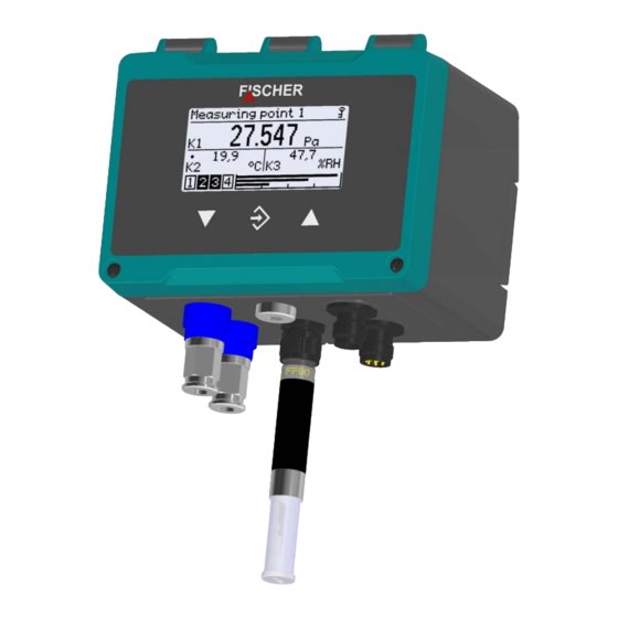
- Page 1 II 3G Ex ec IIC T4 Gc II 3D Ex tc IIIB T125°C Dc Operating manual FT90 Humidity and temperature measuring device PRO-LINE® with optional (differential) pressure measurement...
- Page 2 Great care was taken when compiling the texts and illustrations; Nevertheless, errors cannot be ruled out. The company FISCHER Mess- und Regeltechnik GmbH will not accept any legal responsibility or liability for this.
-
Page 3: Table Of Contents
FISCHER Mess- und Regeltechnik GmbH Table of contents Table of contents 1 Safety instructions ......................6 1.1 General........................... 1.2 Personnel Qualification......................1.3 Personnel Qualification......................1.4 Risks due to Non-Observance of Safety Instructions ............. 1.5 Safety Instructions for the Operating Company and the Operator ......... - Page 4 Table of contents FISCHER Mess- und Regeltechnik GmbH 4 Start-up ..........................25 4.1 Installation control........................25 4.2 Switch on the measuring device..................... 25 4.2.1 Measured value display ......................26 4.2.1.1 2-channel version T/rH ....................... 26 4.2.1.2 3-channel version P/T/rH......................27 4.2.1.3...
- Page 5 FISCHER Mess- und Regeltechnik GmbH Table of contents 5.5.3 Switch output ..........................80 5.5.3.1 SP1 assignment ......................... 80 5.5.3.2 SP1 function ..........................81 5.5.3.3 Switching function........................81 5.5.4 Display ............................82 5.5.4.1 Language............................ 83 5.5.4.2 Designation..........................83 5.5.4.3 Measuring data display....................... 83 5.5.4.4...
-
Page 6: Safety Instructions
1 | Safety instructions FISCHER Mess- und Regeltechnik GmbH 1 Safety instructions 1.1 General This operating manual contains basic instructions for the installation, operation and maintenance of the device that must be followed without fail. It must be read by the installer, the operator and the responsible specialist personnel be- fore installing and commissioning the device. -
Page 7: Safety Instructions For The Operating Company And The Operator
FISCHER Mess- und Regeltechnik GmbH Safety instructions | 1 1.6 Safety Instructions for the Operating Company and the Operator The safety instructions governing correct operation of the instrument must be observed. The operating company must make them available to the installation, maintenance, inspection and operating personnel. -
Page 8: Pictogram Explanation
1 | Safety instructions FISCHER Mess- und Regeltechnik GmbH 1.10 Pictogram explanation DANGER Type and source of danger This indicates a direct dangerous situation that could lead to death or serious injury (highest danger level). 1. Avoid danger by observing the valid safety regulations. -
Page 9: Product And Functional Description
2.2.1 Explosion hazard area classification Devices with the order code FT90 ## ## ## # 0 # 000 R1 # # are classified as electrical equipment for use in potentially explosive areas zone 2 (gases and vapours) and/or zone 22 (dusts). -
Page 10: Function Diagram
2 | Product and functional description FISCHER Mess- und Regeltechnik GmbH 2.3 Function diagram Power Display supply þ û ÿ 24 V AC/DC Option Sensor 1 Channel 1 Switch output 1 Differential pressure Switch output 2 Switch output 3 Switch output 4 µC... -
Page 11: Device Versions
FISCHER Mess- und Regeltechnik GmbH Product and functional description | 2 2.5 Device versions 2.5.1 Process connection Humidity and temperature Humidity and temperature measuring device measuring device with pressure measurement O-ring lock- screw Pneumatic plug-in connection FF90 temperature and humidity sensor... -
Page 12: Atex Model
2 | Product and functional description FISCHER Mess- und Regeltechnik GmbH 2.5.3 ATEX model Earthing connection Conductive housing Fig. 4: ATEX model 2.5.4 Type plate Fig. 5: Humidity/temperature type plate Fig. 6: Pressure/humidity/temperature type plate 12/108 BA_EN_FT90... - Page 13 FISCHER Mess- und Regeltechnik GmbH Product and functional description | 2 Conformity Device type (order code) Basic measuring range Set measuring range Output signal Overload capacity Auxiliary energy Production number Customer item number 10 ATEX marking 11 Special properties 12 Parameter number...
-
Page 14: Assembly
3 | Assembly FISCHER Mess- und Regeltechnik GmbH 3 Assembly 3.1 General The device is designed for installation on assembly plates or wall surfaces. A pre-mounted 35 mm plastic assembly rail is supplied for this purpose. The at- tachment screws are not included in the delivery. -
Page 15: Process Connection
FISCHER Mess- und Regeltechnik GmbH Assembly | 3 3.3 Process connection • By authorized and qualified specialized personnel only. • The pipes need to be depressurized when the instrument is being connec- ted. • Appropriate steps must be taken to protect the device from pressure surges. -
Page 16: Cutting Ring Screw Connections
3 | Assembly FISCHER Mess- und Regeltechnik GmbH process connection type size Pneumatic plug connection Polyamide hose 6 x 4 x 1 mm for hydraulic hoses 8 x 6 x 1 mm CK quick-action screw connection PVC hose 6 x 4 x 1 mm ®... -
Page 17: Electrical Connections
FISCHER Mess- und Regeltechnik GmbH Assembly | 3 3.4 Electrical connections • By authorized and qualified specialized personnel only. • When connecting the unit, the national and international electro-technical regulations must be observed. • Disconnect the system from the mains, before electrically connecting the device. -
Page 18: Devices Only With Switch Outputs
3 | Assembly FISCHER Mess- und Regeltechnik GmbH 3.4.2 Devices only with switch outputs 3.4.2.1 Circuit The device is connected as described below. The admissible load/impedance is stated in the technical data. The connection is performed using a prefabricated sensor connection cable (see the accessories). Alternatively, a prefabricated M12 connector can be used. -
Page 19: M12 Connector 1: Auxiliary Energy And Analogue Output
7 Switch output 4 Blue Fig. 15: 8-pin M12 connector 8 Switch output 4 A Coding 3.4.2.4 M12 connector 3: Sensor input NOTICE! The operating voltage U+ is generated by FT90. Pin Signal Cable colour 1 Operating voltage (internal) Brown 2 I2C bus... -
Page 20: Devices With Switching And Analog Outputs
3 | Assembly FISCHER Mess- und Regeltechnik GmbH 3.4.3 Devices with switching and analog outputs 3.4.3.1 Circuit The device is connected in a 3-wire circuit as described below. The admissible load/impedance is stated in the technical data. The connection is performed us- ing a prefabricated sensor connection cable (see the accessories). -
Page 21: M12 Connector 1: Auxiliary Energy And Analogue Output
7 Switch output 4 Blue Fig. 20: 8-pin M12 connector 8 Switch output 4 A Coding 3.4.3.4 M12 connector 3: Sensor input NOTICE! The operating voltage U+ is generated by FT90. Pin Signal Cable colour 1 Operating voltage (internal) Brown 2 I2C bus... -
Page 22: Device With Modbus
The replacement plate is equipped with a 5-pin M12 flange connector for the Modbus input and a 5-pin M12 flange socket for the Modbus output. The FT90 can be connected to the Modbus RTU network as a slave. Up to 247 devices can be addressed in one line network. -
Page 23: Auxiliary Energy Supply
Please note that the M12 connectors are approved for max. 2A. This value can be exceeded with more than just 12 devices of the type FT90. In this case, an intermediate auxiliary energy feed should be provided at a suitable place. -
Page 24: M12 Plug 1: Modbus In
Black 5 Modbus BUS-R Grey A Coding Fig. 28: M12 bush 5-pin 3.4.4.5 M12 connector 3: Sensor input NOTICE! The operating voltage U+ is generated by FT90. Pin Signal Cable colour 1 Operating voltage (internal) Brown 2 I2C bus White 3 Operating voltage (internal) -
Page 25: Start-Up
FISCHER Mess- und Regeltechnik GmbH Start-up | 4 4 Start-up 4.1 Installation control NOTICE! The check of the pressure lines is not necessary for devices without a pressure connection. Before starting the measuring device: w Check that the pressure lines are mounted correctly. -
Page 26: Measured Value Display
4 | Start-up FISCHER Mess- und Regeltechnik GmbH 4.2.1 Measured value display Depending on the unit model, there are different presentation variants for the measured value display. 4.2.1.1 2-channel version T/rH Assignment: Channel 1: Temperature Channel 2: Humidity 'Meas.data display' The display can be changed using the menu. -
Page 27: 3-Channel Version P/T/Rh
FISCHER Mess- und Regeltechnik GmbH Start-up | 4 4.2.1.2 3-channel version P/T/rH Assignment: Channel 1: Differential pressure Channel 2: Temperature Channel 3: Humidity 'Meas.data display' The display can be changed using the menu. The three channels can be displayed individually or at the same time. The bar graph display always shows all three measuring channels. -
Page 28: Back Lighting
4 | Start-up FISCHER Mess- und Regeltechnik GmbH 4.2.1.3 Back lighting The LC display is equipped with RGB back lighting. This allows it to create vari- ous coloured backgrounds for the measuring data display. Also, the so-called colour changes can be configured that serve to indicate when limits have been overstepped. -
Page 29: Setup
NOTICE! The configuration can also be changed using the keyboard in the configuration menu. 4.4 Modbus RTU interface The FT90 can also be supplied with a Modbus interface. This communication in- terface is set in the menu 'Modbus RTU [} 86]'. BA_EN_FT90... -
Page 30: Operation
5 | Operation FISCHER Mess- und Regeltechnik GmbH 5 Operation 5.1 First steps 5.1.1 Passwörter NOTICE Publicly accessible passwords By publishing the passwords in these operating instructions, the parameterisa- tion is accessible to everyone. Within the scope of security, it is absolutely ne- cessary for the operator of the plant to issue new passwords for all user types. -
Page 31: Menu Tree
FISCHER Mess- und Regeltechnik GmbH Operation | 5 5.1.3 Menu tree Login Quick access Configuration Info Service Fig. 35: Main menu 5.1.3.1 Login Login Log in/Log out Timeout Manage users User 1 User 1 enabled User 1 password User 1 permissions... -
Page 32: Configuration
5 | Operation FISCHER Mess- und Regeltechnik GmbH 5.1.3.3 Configuration Login Login Quick access Quick access Configuration Configuration Channel 1 Channel 1 Channel 2 Channel 2 Analogue output Channel 3 Switch output Analogue output Display Switch output Info Display Service... - Page 33 FISCHER Mess- und Regeltechnik GmbH Operation | 5 Configuration -> Channel -> Flow rate mode Login Quick Access Configuration Channel 1 Mode C1 Linear Flow rate Table Volume flow Linear function Measurement C1 Characteristic C1 Menu expansion Displ.range C1 unit Displ.range C1 start...
- Page 34 5 | Operation FISCHER Mess- und Regeltechnik GmbH Configuration -> Channel -> Volume flow mode Login Quick access Configuration Channel 1 Mode C1 Linear Flow rate Table Volume flow Linear function Measurement C1 Characteristic C1 Menu expansion Displ.range C1 unit Displ.range C1 end...
- Page 35 FISCHER Mess- und Regeltechnik GmbH Operation | 5 5.1.3.3.2 Configuration -> Analog output Login Login Quick access Quick access Configuration Configuration Channel 1 Channel 1 Channel 2 Channel 2 Analog output Channel 3 An.output 1 type Analog output Output 1 assignment An.output 1 type...
-
Page 36: Info
5 | Operation FISCHER Mess- und Regeltechnik GmbH 5.1.3.3.4 Configuration -> Display Login Login Quick access Quick access Configuration Configuration Channel 1 Channel 1 Channel 2 Channel 2 Analog output Channel 3 Switch output Analog output Display Switch output Language... -
Page 37: Navigation In The Menu Tree
FISCHER Mess- und Regeltechnik GmbH Operation | 5 5.1.4 Navigation in the menu tree Pressing the button û takes the user from the 'Meas.data display' screen to the main menu. Measurement point 1 P a 2 1.4 û °C P a 5 4.6... - Page 38 5 | Operation FISCHER Mess- und Regeltechnik GmbH Level 0 Login û Quick access Configuration Info Level 1 Quick access Language Menu Designation Parameter Meas.range C1 unit Menu Measuring range C1 start Parameter Fig. 51: Sidewards in submenu (level 1) 'Back' To leave the menu, move the cursor to the menu item .
-
Page 39: Path Details
FISCHER Mess- und Regeltechnik GmbH Operation | 5 5.1.5 Path details The path information appears in the first line of the display. For space reasons, the paths cannot be shown in full. The menu level is indicated by the number of backslash symbols ('\'). -
Page 40: Value Input
5 | Operation FISCHER Mess- und Regeltechnik GmbH Cursor Selection field \...\Designation û easuring point M N O P Q R D Character list Fig. 55: Editing text In this display, the cursor is controlled with the button û . The cursor can only be moved to the right. - Page 41 FISCHER Mess- und Regeltechnik GmbH Operation | 5 Meas.range C1 start û 020.000 -100.000 100.000 Movement direction of the cursor û Meas.range C1 start 020.000 Edit Cancel Fig. 58: Entry of numerical values, 2nd position A û button repeat automatically returns the user to the action selection. Press- ing the button again saves the value.
-
Page 42: Selection Of Options
5 | Operation FISCHER Mess- und Regeltechnik GmbH 5.1.6.3 Selection of options For example: Path: \Configuration\Channel 2\Measurement C2\Meas.range C2 unit Meas.range C2 unit °C ÿ °F Back Meas.range C2 unit û °C °F Back Fig. 60: Entry of options The cursor is moved with the buttons ÿ and þ . Only one of the offered op- tions can be selected. -
Page 43: Main Menu
FISCHER Mess- und Regeltechnik GmbH Operation | 5 5.2 Main menu Path: \ Level: 0 Pressing the button û takes the user from operating mode to configuration mode. The main menu is displayed. The bar graph display and display of the switch outputs still remain visible. -
Page 44: Login
5 | Operation FISCHER Mess- und Regeltechnik GmbH 5.3 Login Path: \Login Level: 1 Users that are not logged in only have access to the information menu. Users must log in to gain access to the configuration. \Login Log in... -
Page 45: Log In / Log Out
FISCHER Mess- und Regeltechnik GmbH Operation | 5 5.3.1 Log in / log out Path:\Login\Log in Level: 2 Users log in by entering a numerical value. Once the correct password has been entered, the menus for which the user in question has access rights are unlocked. -
Page 46: Timeout
5 | Operation FISCHER Mess- und Regeltechnik GmbH 5.3.2 Timeout Path: \Login\Timeout Level: 2 If the device is switched to configuration mode and no button is pressed, the device returns to the operating mode after the expiry of a defined time period. -
Page 47: User 1
FISCHER Mess- und Regeltechnik GmbH Operation | 5 5.3.3.1 User 1 Path: \Login\Manage users\User 1 Level: 3 \...\...\User1 User 1 enabled User 1 Passw. User 1 permissions Back Fig. 66: User 1 Menu name Description User 1 enabled The user can be enabled with this parameter. - Page 48 5 | Operation FISCHER Mess- und Regeltechnik GmbH 5.3.3.1.1 User 1 permissions Path: \Login\Manage users\User 1\User 1 permissions Level: 4 User 1 permissions View configuration Edit configuration Update firmware Manage users Fig. 67: User 1 permissions Menu name Description View configuration This parameter assigns read permis- sion.
-
Page 49: Administrator
FISCHER Mess- und Regeltechnik GmbH Operation | 5 5.3.3.2 Administrator Path: \Login\Manage users\Administrator Level: 3 \...\...\Administrator Admin. password Back Fig. 68: Administrator 'Admin. The password for the administrator is assigned with the parameter password' . The administrator has unlimited access to all menus and para- meters. -
Page 50: Quick Access
5 | Operation FISCHER Mess- und Regeltechnik GmbH 5.4 Quick access Path: \Quick access Level: 1 \Quick access Language Designation Meas.range C1 unit Meas.range C1 start Fig. 70: Quick access This menu allows quick access to some of the most important parameters of the measuring channels. - Page 51 FISCHER Mess- und Regeltechnik GmbH Operation | 5 Menu name Description Damping C3 This parameter can be used to set damping for the 3rd measuring chan- nel. Back This is the exit point of the 'Quick ac- cess' menu. It takes you back to the main menu.
-
Page 52: Configuration
FISCHER Mess- und Regeltechnik GmbH 5.5 Configuration The device can also be configured with the inTouch® software on a PC. The finished parameter set is then transferred to the FT90 via the USB interface. WARNING Configuration in potentially explosive areas The housing may not be opened within the ATEX area. -
Page 53: Channels 1 To 3
FISCHER Mess- und Regeltechnik GmbH Operation | 5 5.5.1 Channels 1 to 3 The configuration of the channels is largely the same for all versions. However, note the following: 2-channel version 3-channel version Channel 1 Temperature Channel 1 Differential pressure... - Page 54 5 | Operation FISCHER Mess- und Regeltechnik GmbH Differential pressure 3-channel version Temperature/humidity The configuration of channel 1 (differential pressure) differs from the configura- tion of channels 2 and 3 for temperature and humidity. 'Mode' For channel 1, there are the additional configuration submenus 'Characteristic' .
-
Page 55: Mode C1
FISCHER Mess- und Regeltechnik GmbH Operation | 5 5.5.1.1 Mode C1 NOTICE! This menu is available only for devices with a differential pres- sure channel. Path: \Configuration\Channel 1\Mode C1 Level: 3 \...\...\Mode C1 Option field Linear Flow rate Table Volume flow Fig. 75: Mode C1... -
Page 56: Measurement C1
5 | Operation FISCHER Mess- und Regeltechnik GmbH 5.5.1.2 Measurement C1 Path: \Configuration\Channel 1\Measurement C1 Level: 3 \...\...\Measurement C1 Meas.range C1 unit Meas.range C1 start Meas.range C1 end Damping C1 Fig. 76: Measurement C1 In this menu, the linear starting range is configured independent of the set oper- ating mode. - Page 57 FISCHER Mess- und Regeltechnik GmbH Operation | 5 5.5.1.2.1 Measuring range C1 unit Differential pressure Path: \Configuration\Channel 1\Measurement C1\Meas.range C1 unit Level: 4 Meas.range C1 unit mbar Fig. 77: Measuring range C1 unit Implemented pressure units: Unit Description Metric and SI units...
- Page 58 5 | Operation FISCHER Mess- und Regeltechnik GmbH 5.5.1.2.2 Measuring range C1 start Path: \Configuration\Channel 1\Measurement C1\Measur. range C1 start Level:4 Meas.range C1 start 020.000 Edit Cancel Fig. 79: Measuring range C1 start The start value of the measuring range is entered here. This input acts directly on the output signal.
- Page 59 FISCHER Mess- und Regeltechnik GmbH Operation | 5 5.5.1.2.3 Measuring range C1 end Path: \Configuration\Channel 1\Measurement C1\Meas.range C1 end Level: 4 Meas.range C1 End 080.000 Edit Cancel Fig. 81: Measuring range C1 end At this point, the end value of the measuring range is entered. The value range and its limits are displayed automatically.
- Page 60 5 | Operation FISCHER Mess- und Regeltechnik GmbH 5.5.1.2.5 Offset C1 Path: \Configuration\Channel 1\Measurement C1\Offset C1 Level: 4 \...\...\...\Offset C1 0.000 Current measured value Edit Cancel 0.087 Fig. 83: Offset C1 If the measuring data display in the zero-point shows a different value, this can...
- Page 61 FISCHER Mess- und Regeltechnik GmbH Operation | 5 5.5.1.2.6 Zero-point window C1 NOTICE! This menu is only available for devices with differential pressure channel. Path: \Configuration\Channel 1\Measurement C1\Zero-pt. window C1 Level: 4 Zero-pt. window C1 000.000 Edit Cancel Fig. 85: Zero-point window C1 Unsteady readings are not usually a problem during normal operating mode, but this is not true for the idle state, if a measured value of zero is expected.
- Page 62 5 | Operation FISCHER Mess- und Regeltechnik GmbH 5.5.1.2.7 Limits Path: \Configuration\Channel 1\Measurement C1 Level: 3 \...\...\Measurement C1 Damping C1 Offset C1 Zero-pt. window C1 Limit C1 Fig. 87: Limit C1 With this property, the measuring data display can be limited to the Meas.range C1 start...
-
Page 63: Characteristic Curve C1 (Menu Expansion)
FISCHER Mess- und Regeltechnik GmbH Operation | 5 5.5.1.3 Characteristic curve C1 (menu expansion) NOTICE! This menu is available only for devices with a differential pres- sure channel. The menu changes depending on the set operating mode of the measuring channel. - Page 64 5 | Operation FISCHER Mess- und Regeltechnik GmbH 5.5.1.3.2 Characteristic C1 (Table) Path: \Configuration\Channel 1\Characteristic C1 Level: 3 \...\...\Characteristic C1 Displ.range C1 unit Table C1 Back Fig. 89: Characteristic C1 (table) Menu name Description Displ.range C1 unit A unit for the display value is defined with this parameter.
- Page 65 FISCHER Mess- und Regeltechnik GmbH Operation | 5 The first value pair is assigned to the start of the measuring range and the last value pair to the end of the measuring range. There is a linear interpolation of the characteristic between two values. The input values must either be continu- ously rising or falling.
- Page 66 5 | Operation FISCHER Mess- und Regeltechnik GmbH 5.5.1.3.3 Characteristic C1 (volume flow) Path: \Configuration\Channel 1\Characteristic C1 Level: 3 Characteristic C1 Displ.range C1 unit Displ.range C1 end K factor C1 Air density C1 Fig. 92: Characteristic C1 (volume flow) Menu name Description Displ.range C1 unit...
- Page 67 FISCHER Mess- und Regeltechnik GmbH Operation | 5 5.5.1.3.3.1 Display range C1 unit Path: \Configuration\Channel 1\Characteristic C1\Displ.range C1 unit Level: 4 Displ.range C1 unit m³/h Back Fig. 94: Display range C1 unit The following units are available for selection: Cubic metre per hour...
- Page 68 5 | Operation FISCHER Mess- und Regeltechnik GmbH 5.5.1.3.3.2 Formula C1 Path: \Configuration\Channel 1\Characteristic C1\Formula C1 Level: 4 \...\...\...\Formula C1 Standard Comefri EBM Papst Fläkt Woods Fig. 95: Formula C1 The following table lists the formulas specified by the respective manufacturer for calculating the volume flow.
- Page 69 FISCHER Mess- und Regeltechnik GmbH Operation | 5 5.5.1.3.4 Characteristic C1 (linear function) Path: \Configuration\Channel 1\Characteristic C1 Level: 3 Characteristic C1 Displ.range C1 unit Displ.range C1 start Displ.range C1 end Slope C1 Fig. 98: Characteristic curve C1 (linear function) Menu name Description Displ.range C1 unit...
-
Page 70: Number Format C1
5 | Operation FISCHER Mess- und Regeltechnik GmbH 5.5.1.4 Number format C1 Path: \Configuration\Channel 1\Number format C1 Level: 3 \...\...\Number format C1 ±123456 ±12345.6 ±1234.56 ±123.456 Fig. 100: Number format C1 The number of decimal places can be determined with this menu. All theoretic- ally possible variants are made available for selection. -
Page 71: Colour Change C1
FISCHER Mess- und Regeltechnik GmbH Operation | 5 5.5.1.5 Colour change C1 Path: \Configuration\Channel 1\Colour change C1 Level: 3 \...\...\Colour change C1 Col.ch. C1 red–grn Col.ch. C1 grn–red Col.ch. C1 red–ylw Col.ch. C1 ylw–grn Fig. 101: Colour change C1 This menu is used to set the switch threshold for the colour change of the back lighting. - Page 72 5 | Operation FISCHER Mess- und Regeltechnik GmbH 5.5.1.5.1 Colour change C1 type: red/green The following switching thresholds are relevant for this colour change: Basic measuring range GREEN Fig. 102: Colour change red/green Meas.range C1 start Measurement C1 See menu : [} 56] Col.ch.
- Page 73 FISCHER Mess- und Regeltechnik GmbH Operation | 5 5.5.1.5.2 Colour-change C1 type: red/yellow/green The following switching thresholds are relevant for this colour change: Basic measuring range YELLOW GREEN YELLOW Fig. 104: Colour change red/yellow/green Meas.range C1 start Measurement C1 See menu : [} 56]...
- Page 74 5 | Operation FISCHER Mess- und Regeltechnik GmbH 5.5.1.5.3 Colour change C1 hysteresis Path: \Configuration\Channel 1\Colour change C1\Col.ch. C1 hyst. Level: 4 Col.ch. C1 hyst. 10.000 Edit OK Cancel Fig. 106: Colour change C1 hyst. This parameter can be used to define an hysteresis for the switch thresholds of the colour change.
- Page 75 FISCHER Mess- und Regeltechnik GmbH Operation | 5 (ii) Upper switching thresholds S3 and S4 In case of a colour change from a lower to a higher risk level, the hysteresis acts with an decreasing signal. Increasing signal -0.5 Falling signal Fig. 109: Example: Hysteresis S4...
- Page 76 5 | Operation FISCHER Mess- und Regeltechnik GmbH 5.5.1.5.5 Colour change C1 delay off Path: \Configuration\Channel 1\Colour change C1\Col.ch. C1 delay off Level: 4 Col.ch. C1 delay off Edit OK Cancel Fig. 111: Colour change C1 delay off The deactivation delay acts when changing from a higher risk level to a lower risk level.
-
Page 77: Analog Output
FISCHER Mess- und Regeltechnik GmbH Operation | 5 5.5.2 Analog output The number of analog outputs depends on the version. 2-channel version 2 analog outputs 3-channel version 3 analog outputs Path: \Configuration\Analog output Level: 2 \...\Analog output An.output 1 type An.output 1 assignmnt... -
Page 78: Analog Output 1 Type
5 | Operation FISCHER Mess- und Regeltechnik GmbH 5.5.2.1 Analog output 1 type Path: \...\...\An.output 1 type Level: 3 \...\...\An.output 1 type Current 0...20 mA Current 4...20 mA Voltage 0...10 V Voltage 2...10 V Fig. 114: Analog output 1 type The signals can be set for output 1:... -
Page 79: Signal Limits
FISCHER Mess- und Regeltechnik GmbH Operation | 5 5.5.2.3 Signal limits NOTICE! The limit parameters apply for both output signals. The output signal can by limited by the limit parameters. This primarily serves to prevent error messages in downstream systems caused by brief overstepping of measuring ranges. -
Page 80: Switch Output
5 | Operation FISCHER Mess- und Regeltechnik GmbH 5.5.3 Switch output Path: \Configuration\Switch output Level: 2 \...\Switch output SP1 assignment SP1 on SP1 off SP1 delay on Fig. 117: Switch output NOTICE! As the configuration for each switch output is the same, only the parameters for the first switch output are shown here. -
Page 81: Sp1 Function
FISCHER Mess- und Regeltechnik GmbH Operation | 5 5.5.3.2 SP1 function Path: \Configuration\Switch output\SP1 function Level: 3 \...\...\SP1 function Normally open Normally closed Back Fig. 119: SP1 function The function of this contact is defined with this parameter. 5.5.3.3 Switching function The function of the individual parameters is explained for all switch points using Switch point 1 as an example. -
Page 82: Display
5 | Operation FISCHER Mess- und Regeltechnik GmbH Delay The switching behaviour of the contact can be delayed with the two parameters SP1 delay on SP1 delay off Time SP1 delayed Time SP1 delay off SP1 delay on Fig. 121: Delay 5.5.4 Display... -
Page 83: Language
FISCHER Mess- und Regeltechnik GmbH Operation | 5 5.5.4.1 Language Path: \Configuration\Display\Language Level: 3 \...\Language German English Español Français Fig. 123: Language Parameter name Language German German language English English language Español Spanish language Français French language Italiano Italian language Magyar Hungarian language 5.5.4.2 Designation... -
Page 84: Colour Change Assignment
5 | Operation FISCHER Mess- und Regeltechnik GmbH 5.5.4.4 Colour change assignment Path: \Configuration\Display\Col.ch. assignment Level: 3 Col.ch. assignment Channel 1 Channel 2 Channel 3 Back Fig. 126: Colour change assignment This menu is used to define the channel that controls the colour change. If mul- tiple channels are selected, the colour change takes place once one of the channels triggers a colour change. -
Page 85: Lcd Colour
FISCHER Mess- und Regeltechnik GmbH Operation | 5 5.5.4.5 LCD colour Path: \Configuration\Display\LCD colour Level: 3 \...\...\LCD colour Green Yellow Fig. 128: LCD colour The following colours can be selected for the back lighting. Green Yellow Blue Magenta Cyan White Red/green... -
Page 86: Lcd Contrast
5 | Operation FISCHER Mess- und Regeltechnik GmbH 5.5.4.7 LCD contrast Path: \Configuration\Display\LCD contrast Level: 3 \...\...\LCD contrast Edit OK Cancel Fig. 130: LCD contrast This parameter can be used to set the contrast for the LC display. 5.5.5 Modbus RTU NOTICE! This menu is only available for devices with a Modbus interface. -
Page 87: Baud Rate
FISCHER Mess- und Regeltechnik GmbH Operation | 5 5.5.5.1 Baud rate Path: \Configuration\Modbus RTU\Baud rate Level: 3 \...\...\Baud rate 2400 baud 4800 baud 9600 baud 14400 baud Fig. 132: Baud rate Baud rates Description 2400 Baud Options for data transmission. 4800 Baud... -
Page 88: Modbus Address
5 | Operation FISCHER Mess- und Regeltechnik GmbH 5.5.5.3 Modbus address Path: \Configuration\Modbus RTU\Modbus address Level: 3 \...\...\Modbus address Edit OK Cancel Fig. 134: Modbus address Addresses from 1 to 247 can be used. 5.5.5.4 Byte order Path: \Configuration\Modbus RTU\Byte order... -
Page 89: Info
FISCHER Mess- und Regeltechnik GmbH Operation | 5 5.6 Info Path: \Info Level: 1 \Info Device Version Input 1 Input 2 Fig. 136: Info Various information for configuration and setting of the device is provided in this menu. Menu name Description Dev. - Page 90 5 | Operation FISCHER Mess- und Regeltechnik GmbH Menu name Description Back This is the exit point of the service menu. It takes you back to the main menu. To be able to use a USB drive, you must open the housing first.
-
Page 91: Servicing
FISCHER Mess- und Regeltechnik GmbH Servicing | 6 6 Servicing 6.1 Maintenance The instrument is maintenance-free. We recommend the following regular in- spection to guarantee reliable operation and a long service life: • Check the function in combination with downstream components. -
Page 92: Technical Data
7 | Technical data FISCHER Mess- und Regeltechnik GmbH 7 Technical data 7.1 General Type designation FT90 Measuring variable Temperature Humidity Differential pressure Measurement Temperature Band gap principle Humidity Capacitive Print Piezo-resistive 7.2 Input variables 7.2.1 Temperature and humidity Sensor assembly Temperature measuring range... -
Page 93: Output Sizes
FISCHER Mess- und Regeltechnik GmbH Technical data | 7 Symmetric measuring ranges: Measuring range Overload Bursting Sensor pressure -25 to +25 Pa 750 mbar 1 bar -40 to +40 Pa 750 mbar 1 bar -60 to +60 Pa 750 mbar... -
Page 94: Measuring Accuracy
7 | Technical data FISCHER Mess- und Regeltechnik GmbH Switch outputs The assignment of the switch outputs to the channels can be configured freely. Number of switch outputs Type Potential-free semiconductor switch (MOS- FET) Progr. switching function 1-pole open contact (NO) 1-pole break contact (NC) Max. -
Page 95: Temperature
FISCHER Mess- und Regeltechnik GmbH Technical data | 7 7.4.2 Temperature The limit values apply for plastic and all sensors mounted at an offset. To ensure that the specified measurement error is upheld for stainless steel sensors mounted directly on the device, an air flow of at least 0.1 m/s must be guaranteed. -
Page 96: Digital Interfaces
7 | Technical data FISCHER Mess- und Regeltechnik GmbH Measuring range Measurement error Tc-zero Tc span [%/10K] [%/10K] Typ. Max. Typ. Max. Typ. Max. -4 to +4 mbar -400 to +400 Pa 0.05 -6 to +6 mbar -600 to +600 Pa 0.75... -
Page 97: Auxiliary Energy
FISCHER Mess- und Regeltechnik GmbH Technical data | 7 Modbus RTU interface interface RS 485 Report Modbus RTU Modbus specification Application Protocol Specification V1.1b3 (April 26, 2012) Address 1 … 247 Baud rate 2400 … 115200 Baud Parity Even, uneven, parity Stopbits 1…2... -
Page 98: Display
7 | Technical data FISCHER Mess- und Regeltechnik GmbH 7.8 Display Display Full graphic LC display Resolution 128 x 64 Pixel Backlight Measured value display 6 digits 7.9 Construction design Process connection Outer Ø Inner Ø CK screw connections Hose... -
Page 99: Dimensional Drawings
FISCHER Mess- und Regeltechnik GmbH Technical data | 7 7.9.2 Dimensional drawings All dimensions in mm unless otherwise stated 81.5 Mounting rail Electrical connection Process connection (a) Version with pressure connection Mounting rail Process connection Blind plug (b) Version without pressure connection... - Page 100 7 | Technical data FISCHER Mess- und Regeltechnik GmbH Mounting rail Fig. 143: Mounting rail Process connection Screw connection Screw connection Screw connection removable disk removable disk removable disk G⅛ G⅛ G⅛ G⅛ Cutting ring G⅛ Union nut Union nut Cutting ring...
-
Page 101: Order Code
FISCHER Mess- und Regeltechnik GmbH Order code | 8 8 Order code Code No. 10 11 12 13 14 Type Differential pressure measuring range: [1,2] [1,2] [1,2] Without differential pressure measuring -20 … +80 Pa 0 … 25 Pa 0 … 40 Pa 0 …... - Page 102 8 | Order code FISCHER Mess- und Regeltechnik GmbH Humidity and temperature measuring range: [3,4] Measuring range Sensor material Humidity 0 to 100% rH Plastic (POM) Temperature -40 to 100°C Humidity 0 to 100% rH Stainless steel Temperature -40 to 100°C...
- Page 103 FISCHER Mess- und Regeltechnik GmbH Order code | 8 Membrane keypad: [15] FISCHER Neutral Configuration: [16] Preset at the factory 'Standard' configuration 'Customer-specific' configuration The configuration can be changed on the device at any time. The delivery state is defined by the order code. For details, see the operating instructions.
-
Page 104: Accessories
8 | Order code FISCHER Mess- und Regeltechnik GmbH 8.1 Accessories M12 connection cables Designation No. of Length Order no. poles PUR connection cable with M12 coupling, 4 poles 06401993 A-coded 06401994 06401563 10 m 06401572 5 poles 06401995 06401996... -
Page 105: Attachments
FISCHER Mess- und Regeltechnik GmbH Attachments | 9 9 Attachments 9.1 EU Declaration of Conformity Fig. 146: CE_DE_FT90 BA_EN_FT90 105/108... - Page 106 9 | Attachments FISCHER Mess- und Regeltechnik GmbH Fig. 147: CE_DE_FT90_ATEX 106/108 BA_EN_FT90...
- Page 107 FISCHER Mess- und Regeltechnik GmbH Notes BA_EN_FT90 107/108...
- Page 108 Mess- und Regeltechnik GmbH Bielefelder Str. 37a D-32107 Bad Salzuflen Tel. +49 5222 974-0 Fax +49 5222 7170 www.fischermesstechnik.de info@fischermesstechnik.de Technische Änderungen vorbehalten. Subject to technical changes. Sous réserve de modifications techniques.
Need help?
Do you have a question about the FT90 and is the answer not in the manual?
Questions and answers