Ruijie RG-S6510-4C Series Hardware Installation And Reference Manual
Hide thumbs
Also See for RG-S6510-4C Series:
- Hardware installation and reference manual (89 pages) ,
- Hardware installation and reference manual (77 pages)
Table of Contents
Advertisement
Quick Links
Advertisement
Table of Contents
Troubleshooting

Related Manuals for Ruijie RG-S6510-4C Series


Summary of Contents for Ruijie RG-S6510-4C Series
- Page 1 Ruijie RG-S6510-4C Series Switches Hardware Installation and Reference Guide...
- Page 2 This document is provided “as is”. The contents of this document are subject to change without any notice. Please obtain the latest information through the Ruijie Networks website. Ruijie Networks endeavors to ensure content accuracy and will not shoulder any responsibility for losses and damages caused due to content omissions, inaccuracies or errors.
- Page 3 Appendix C “Lightening Protection” Appendix D “Cabling Recommendations in Installation” Appendix E “Site Selection” Appendix F “Mini USB Console Driver Installation” Obtaining Technical Assistance Ruijie Networks Website: https://www.ruijienetworks.com/ Technical Support Website: https://ruijienetworks.com/support Case Portal: https://caseportal.ruijienetworks.com ...
- Page 4 Documents Description Describes network protocols and related mechanisms that supported by the Configuration Guide product, with configuration examples. Describes the related configuration commands, including command modes, Command Reference parameter descriptions, usage guides, and related examples. Symbol Conventions Means reader take note. Notes contain helpful suggestions or references. Means reader be careful.
-
Page 5: Product Overview
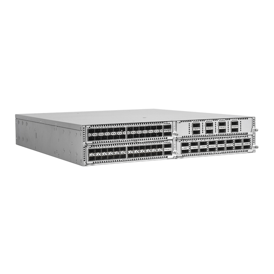
Product Overview 1 Product Overview RG-S6510-4C series switch is a data center-oriented high-density 10G layer 3 IPv6 box-type switch. They are mainly applicable to data center scenario to provide convergence and access service for the servers with 10G ports. The RG-S6510-4C series switch includes a switch and three extension modules. - Page 6 4C Series Switch Hardware Installation and Reference Guide Product Overview Refer to Appendix B Fiber Module The supported modules may change. Please contact Ruijie Networks for details. SFP28 Port Supported. The number of ports depends on the extension module. QSFP28 Port Supported.
- Page 7 RG-SS6510 4C Series Switch Hardware Installation and Reference Guide Product Overview Front Panel Figure 1-2 Front Panel of the S6510-4C Notes: Sub Slot 1 Sub Slot 3 Sub Slot 2 Sub Slot 4 Back Panel Figure 1-3 Back Panel of the S6510-4C Notes: Fan Module Slot 8.
- Page 8 RG-SS6510 4C Series Switch Hardware Installation and Reference Guide Product Overview External Ports The RG-S6510-4C provides the following ports: Universal serial bus (USB) port: This port can connect with USB memory to save logs, host versions, warnings and other diagnostic messages. Therefore, it is more convenient to upgrade the software version of the switch on line and save the log information.
- Page 9 The port is transmitting or receiving data. Power Supply The RG-S6510-4C series switch supports power supply the PA800I-F. The smart power supply module supports power management, and the host can read input power, input current, and temperature in real time. The power supply module supports hot swapping.
- Page 10 RG-SS6510 4C Series Switch Hardware Installation and Reference Guide Product Overview 1.2 Modules RG-S6510-4C switch supports the following modules: M6500-24VS2CQ, M6500-08CQ, M6500-16QXS, RG-PA800I-F, and M6500-FAN-F. 1.2.1 M6500-24VS2CQ Module Appearance Figure 1-6 M6500-24VS2CQ Notes: Status Indicator 25F-26F Port Status Indicator 25G/10G SFP28 Port 100G/40G QSFP28 Port 1F-24F Port Status Indicator External Ports...
- Page 11 RG-S6510-4C Port Type 24 25G SFP28 ports and 2 100G QSFP28 ports See Appendix B Transmission Medium The supported module may change. Please contact Ruijie Networks for details. Hot Swapping Not Supported Power Consumption <57W GB9254-2008 CLASS A Safety specification...
- Page 12 Module M6500-08CQ Device RG-S6510-4C Port Type 8 100G QSFP28 ports See Appendix B Transmission Medium The supported module may change. Please contact Ruijie Networks for details. Hot Swapping Not Supported Power Consumption <57W GB9254-2008 CLASS A Safety specification GB4943-2011 Operating 0°...
- Page 13 The port is receiving or transmitting data at 40G. Specifications Module M6500-16QXS Device RG-S6510-4C Port Type 16 40G QSFP28 ports See Appendix B Transmission Medium The supported module may change. Please contact Ruijie Networks for details. Hot Swapping Not Supported - 11 -...
- Page 14 RG-SS6510 4C Series Switch Hardware Installation and Reference Guide Product Overview Power Consumption <99W GB9254-2008 CLASS A Safety specification GB4943-2011 Operating 0° C to 40° C (32° F to 104° F) Temperature Storage -40° C to 70° C (-40° F to 158° F) Temperature Operating Humidity 10% to 90% RH (non-condensing)
- Page 15 RG-SS6510 4C Series Switch Hardware Installation and Reference Guide Product Overview Solid red The fan fails or stops. Specifications Model M6500-FAN-F Ventilation Rate 109.43 CFM Rotation 11000 RPM Speed Consumption 44.4 W Weight 0.25 kg (0.55 lbs) Dimension(W x 166 mm x 83 mm x 83 mm (6.54 in. x 3.27 in. x 3.27 in.) D x H) 1.2.5 RG-PA800I-F RG-PA800I-F is a smart power supply, obtaining power status, output power, current and working temperature in real...
- Page 16 RG-SS6510 4C Series Switch Hardware Installation and Reference Guide Product Overview The power is PS off, 12VBS. Blinking green The power is in cold backup status and does not output power. An error occurs, e.g., overcurrent, overvoltage or Solid red fan fault.
-
Page 17: Preparation Before Installation
RG-SS6510 4C Series Switch Hardware Installation and Reference Guide Preparation before Installation 2 Preparation before Installation 2.1 Safety Precautions To avoid body injury and device damage, please carefully read the safety precautions before you install the RG-S6510-4C. The following safety precautions do not cover all possible dangers. 2.1.1 Installation Safety ... - Page 18 RG-SS6510 4C Series Switch Hardware Installation and Reference Guide Preparation before Installation Any nonstandard and inaccurate electrical operation can cause accidents such as fires or electrical attacks, thus causing severe, or even fatal damages to human bodies and the devices. Direct or indirect touch through a wet object on high-voltage and mains supply can bring a fatal danger.
-
Page 19: Installation Site Requirements
2.2.2 Ventilation Requirements For the RG-S6510-4C series products, leave sufficient space in the front and at the back of the chassis (at least 20cm) for ventilation. After various cables are connected, bundle the cables or place them in the cable management bracket to avoid blocking air inlets. -
Page 20: Cleanness Requirements
RG-SS6510 4C Series Switch Hardware Installation and Reference Guide Preparation before Installation In an environment with high temperature, the equipment is subjected to even greater harm, as its performance may degrade significantly and its service life may be shortened at high temperature for long that expedites the aging process. -
Page 21: Emi Consideration
All the above constitute the comprehensive grounding requirements. The grounding resistance should be less than 1Ω. There is one grounding connector at the right bottom of the chassis of RG-S6510-4C series switch. The grounding connector is pasted with conspicuous warning labels. -
Page 22: Precaution For Fiber Connection
Air-laid paper, fiber end microscope Meter Multimeter, errormeter, optic-power meter RG-S6510-4C series is not shipped with a tool kit. You need to prepare a tool kit by yourself. 2.5 Unpacking and Checking Goods Checklist Chassis, Yellow/green grounding cables; Quick installation guide; Packing list, Pouched... -
Page 23: Product Installation
Product Installation 3 Product Installation RG-S6510-4C series Ethernet switch must be used and fixed in the room. Make sure you have carefully read part 2, and be sure that the requirements set forth in part 2 have been met. 3.1 Installation Procedure... -
Page 24: Cabinet Installation
RG-SS6510 4C Series Switch Hardware Installation and Reference Guide Product Installation The related network cables have already been deployed at the installation location. 3.3 Cabinet Installation Precautions When you install the cabinet, pay attention to the following requirements: All expansion bolts for fastening the cabinet base to the ground should be installed and tightened in sequence from bottom up (large plain washer, spring washer, and nut), and the installation holes on the base and the expansion bolts should be well aligned. - Page 25 Mounting the Switch to a Rack The RG-S6510-4C series switch is qualified for EIA standard and can be installed in 19-inch wiring cabinet. During the process of installation, keep the front panel of the switch forward. It is recommended use tray to install the RG-S6510-4C series switch and fix the tray on the bracket, or use the rear bracket provided with the switch.
- Page 26 RG-SS6510 4C Series Switch Hardware Installation and Reference Guide Product Installation Secure a rack rail on each side of the chassis. Align inner rails with the front of the rack rails. Slide the inner rails into the rack rails, keeping the pressure even on both sides.
-
Page 27: Installing And Removing A Fan Module
RG-SS6510 4C Series Switch Hardware Installation and Reference Guide Product Installation Distinguish the left and the right rear brackets according to the marked directions. The rear brackets provided are only applicable for cabinets with depth of 800mm - 1200mm. Mounting the Switch to a Workbench In some cases, users do not have the 19-inch standard cabinet. - Page 28 RG-SS6510 4C Series Switch Hardware Installation and Reference Guide Product Installation Withdraw the fan module uprightly and slowly. Install a blank panel to the empty slot to prevent dust from entering the switch. 3.6 Installing and Removing an Extension Module S6510-4C series module are not hot swappable.
- Page 29 RG-SS6510 4C Series Switch Hardware Installation and Reference Guide Product Installation Removing an Extension Module Step 1. Unplug all cables on the panels like optical fiber and RJ45 twisted pairs. Step 2. Use the screwdriver to loosen the captive screws of the extension module. Step 3.
- Page 30 RG-SS6510 4C Series Switch Hardware Installation and Reference Guide Product Installation Insert the power module smoothly. Please pay attention to the direction of the power panel to avoid wrong insertion. If it is difficult or even impossible to insert the module, pull out the module, make sure the extension module and guide rail are well aligned, and then insert the module again.
-
Page 31: Connecting The External Interface Cables
RG-SS6510 4C Series Switch Hardware Installation and Reference Guide Product Installation 3.8 Grounding A PGND is installed on the back of RG-S6510-4C. First connect the PGND to the grounding terminal of the cabinet and then connect the grounding terminal to the grounding bar of the equipment room. Precautions ... -
Page 32: Binding The Cables
RG-SS6510 4C Series Switch Hardware Installation and Reference Guide Product Installation Insert the twisted pair with the RJ45 port into the appropriate interface according to the identification on the panel of the line card. Distinguish the crossover cable and straight-through cable. 3.11 Binding the Cables Precautions ... - Page 33 RG-SS6510 4C Series Switch Hardware Installation and Reference Guide Product Installation To avoid body injury and components damage, cut off power supply before checking the installation. - 31 -...
-
Page 34: System Debugging
RG-SS6510 4C Series Switch Hardware Installation and Reference Guide System Debugging 4 System Debugging 4.1 Establishing the Configuration Environment Establishing the Configuration Environment Connect the PC to the console port of the switch through the console cable, as shown in Figure 4-1. Figure 4-1 Schematic diagram of the configuration environment Connecting the Console Cable Connect one end of the DB-9 jack of the console cable to the serial port of the PC. - Page 35 RG-SS6510 4C Series Switch Hardware Installation and Reference Guide System Debugging Figure 4-2 Enter the name of the new connection and click OK. A window appears as shown in Figure 4-3. In the column of Connect Using field, select the serial port you want to use. Figure 4-3 After the serial port is selected, please click OK.
-
Page 36: Power-On Startup
RG-SS6510 4C Series Switch Hardware Installation and Reference Guide System Debugging After the serial port parameters are set, click OK to enter hyper terminal window. 4.2 Power-on Startup Checking before Power-on Check if the switch is fully grounded. Check if the fan module and the power module are correctly installed. -
Page 37: Monitoring And Maintenance
Working status of fan and power supply Temperature status For the monitoring commands, refer to RG-S6510-4C Series Switch RGOS Configuration Guide. 5.2 Hardware Maintenance Extension Module Maintenance To replace a board, do replacement according to the instructions provided in Sections of Installing Modules and Removing Modules. - Page 38 Replacing Lithium Battery The built-in lithium batteries can support the real time clock of the RG-S6510-4C series switch without external power supply. Please contact the technical support representatives of Ruijie Networks for replacing lithium batteries. Technical staff of Ruijie Networks will replace the battery of the same model.
-
Page 39: Troubleshooting
Check the indicators on the device and the modules Check the connection of the serial ports and its parameters Check the connection of the fibers or cables of various ports Contact Technical Support of Ruijie Networks for hardware problems - 37 -... -
Page 40: Common Troubleshooting Procedures
RG-S6510-4C Software Configuration Guide. If not, modify the serial port configuration parameters. If there is still no serial port printed information, please contact Ruijie Customer Service Department for technical support. - Page 41 Check whether the module is inserted correctly. If the newly-inserted module still cannot be powered on even though the checking is ok, please contact Ruijie Customer Service Department for technical support. Fault 7: The link cannot be set up between fiber interfaces [Fault Description] The system runs normally.
-
Page 42: Appendix A Connectors And Connection Media
RG-SS6510 4C Series Switch Hardware Installation and Reference Guide Appendix A Connectors and Connection Media Appendix A Connectors and Connection Media 10GBASE-T/1000BASE-T/100BASE-TX Port 10GBASE-T/1000BASE-T/100BASE-TX is a port that supports self-adaptation of three rates, and automatic MDI/MDIX Crossover at these three rates. 10GBASE-T complies with IEEE 802.3an standard, and the supported cables and cabling distances are listed in the following table. - Page 43 RG-SS6510 4C Series Switch Hardware Installation and Reference Guide Appendix A Connectors and Connection Media Figure A-1 Four twisted pairs of the 1000BASE-T In addition to the above cables, the 100BASE-TX can use up to 100m of 100-ohm CAT5. Figure A-2 shows the definition of pin signal concerning the 100BASE-TX: Figure A-2 Definition of pin signal concerning the 100BASE-TX Socket...
-
Page 44: Appendix B 10G, 25G, 40G And 100G Module
RG-SS6510 4C Series Switch Hardware Installation and Reference Guide Appendix B 10G, 25G, 40G and 100G Module Appendix B 10G, 25G, 40G and 100G Module We provide 1000M SFP modules (Mini-GBIC modules), 10G SFP+ modules, 40G QSFP+ modules, 100G QSFP28 modules and AOC modules. - Page 45 RG-SS6510 4C Series Switch Hardware Installation and Reference Guide Appendix B 10G, 25G, 40G and 100G Module (nm) Fiber Size Bandwidth Cabling Transmitted Received (μm) Type (MHz· km) Distance Light (dbm) Light (dbm) VG-SFP-SR-M 100m (840, 860) connecto 50/125 4700 -8.4 -10.3 M850...
- Page 46 RG-SS6510 4C Series Switch Hardware Installation and Reference Guide Appendix B 10G, 25G, 40G and 100G Module Copper Conductor Support Module Connector Model Cable Wire Diameter Data Rate(Gb/s) Type Type Length (m) (AWG) (Yes/No) 4lanes*10.3125 40G-QSFP-STACK1M Passive QSFP+ (Perlane) 4lanes 40G-QSFP-STACK3M Passive QSFP+...
-
Page 47: Appendix C Lightning Protection
RG-SS6510 4C Series Switch Hardware Installation and Reference Guide Appendix C Lightning Protection Appendix C Lightning Protection Installing AC Power Arrester (lightning protection cable row) The external lightning protection cable row should be used on the AC power port to prevent the switch from being struck by lightning when the AC power cable is introduced from the outdoor and directly connected to the power port of the switch. - Page 48 RG-SS6510 4C Series Switch Hardware Installation and Reference Guide Appendix C Lightning Protection Installing the Ethernet Port Arrester During the switch usage, the Ethernet port arrester should be connected to the switch to prevent the switch damage by lightning before the outdoor network cable connects to the switch . Tools: Cross or straight screwdriver, Multimeter, Diagonal pliers Installation Steps: Tear one side of the protection paper for the double-sided adhesive tape and paste the tape to the framework of the...
- Page 49 RG-SS6510 4C Series Switch Hardware Installation and Reference Guide Appendix C Lightning Protection You should pay attention to the following conditions during the actual installation to avoid influencing the performance of the Ethernet port arrester: Reversed direction of the arrester installation. You shall connect the external network cable to the “IN” end and connect the switch Ethernet port to the “OUT”...
-
Page 50: Appendix D Cabling Recommendations In Installation
RG-SS6510 4C Series Switch Hardware Installation and Reference Guide Appendix D Cabling Recommendations in Installation Appendix D Cabling Recommendations in Installation When the switch is installed in a standard 19-inch cabinet, the cables are tied in the binding rack on the cabinet by the cable management bracket, and top cabling or bottom cabling is adopted according to the actual situation in the equipment room. - Page 51 RG-SS6510 4C Series Switch Hardware Installation and Reference Guide Appendix D Cabling Recommendations in Installation Cables of different types (such as power cords, signal cables, and grounding cables) should be separated in cabling and bundling and no mixed bundling is allowed. When they are close, crossover cabling can be adopted. In the case of parallel cabling, power cords and signal cables should maintain a distance not less than 30 mm.
- Page 52 RG-SS6510 4C Series Switch Hardware Installation and Reference Guide Appendix D Cabling Recommendations in Installation Cables not to be assembled or remaining parts of cables should be folded and placed in a proper position of the cabinet or cabling slot. The proper position indicates a position that will not affect device running or cause device damage or cable damage during commissioning.
- Page 53 RG-SS6510 4C Series Switch Hardware Installation and Reference Guide Appendix D Cabling Recommendations in Installation Figure D-4 Cable fastening The hard power cable should be fastened at the terminal connection area to prevent stress on terminal connection and cable. ...
-
Page 54: Appendix E Site Selection
RG-SS6510 4C Series Switch Hardware Installation and Reference Guide Appendix E Site Selection Appendix E Site Selection The machine room should be at least 5km away from the heavy pollution source such as the smelter, coal mine and thermal power plant, 3.7km away from the medium pollution source such as the chemical industry, rubber industry and electroplating industry, and 2km away from the light pollution source such as the food manufacturer and leather plant.
Need help?
Do you have a question about the RG-S6510-4C Series and is the answer not in the manual?
Questions and answers