Ruijie RG-S6580-48CQ8QC Hardware Installation And Reference Manual
Hide thumbs
Also See for RG-S6580-48CQ8QC:
- Hardware installation and reference manual (55 pages) ,
- Hardware installation and reference manual (74 pages)

Subscribe to Our Youtube Channel
Related Manuals for Ruijie RG-S6580-48CQ8QC


Summary of Contents for Ruijie RG-S6580-48CQ8QC
- Page 1 Ruijie RG-S6580-48CQ8QC Switch Hardware Installation and Reference Guide Document Version: V2.0 Date: August 31, 2023 Copyright © 2023 Ruijie Networks...
- Page 2 Unless agreed upon otherwise in the contract, Ruijie Networks does not provide any explicit or implicit statements or warranties regarding the content of this document.
-
Page 3: Preface
Preface Intended Audience This document is intended for: Network engineers Technical support and servicing engineers Network administrators Technical Support Ruijie Networks website: https://www.ruijienetworks.com/ Online support center: https://ruijienetworks.com/support Case portal: https://caseportal.ruijienetworks.com Community: https://community.ruijienetworks.com ... - Page 4 Notes The manual provides configuration information, including models, port types, and command line interfaces, for reference purposes only. In the event of any discrepancy or inconsistency between the manual and the actual version, the actual version shall take precedence.
-
Page 5: Table Of Contents
Contents Preface ..............................I 1 Overview ............................1 1.1 About the RG-S6580-48CQ8QC ....................1 1.2 Component Modules ........................1 1.3 Chassis ............................2 1.3.1 Appearance ........................2 1.3.2 LEDs ..........................4 1.3.3 Ports ..........................5 1.3.4 Cooling ........................... 6 1.3.5 Technical Specifications ....................7 1.3.6 Asset Tag ........................ - Page 6 2.1.1 General Precautions ....................18 2.1.2 Chassis-Lifting Guidelines ................... 18 2.1.3 Electricity Safety ......................18 2.1.4 Preventing ESD Damage ..................... 19 2.1.5 Laser Safety ......................... 19 2.1.6 Storage Guidelines ...................... 19 2.2 Site Requirements ........................20 2.2.1 Floor Loading ....................... 20 2.2.2 Airflow ...........................
- Page 7 3.2.1 Installation Guidelines ....................29 3.2.2 Procedure ........................29 3.3 Installing the Chassis ....................... 29 3.3.1 Installation Guidelines ....................29 3.3.2 Mounting the Brackets ....................30 3.3.3 Mounting the Chassis on the Rack ................30 3.4 Installing the Protective Grounding Wire ................. 31 3.4.1 Installation Guidelines ....................
- Page 8 5 Monitoring and Maintenance ......................40 5.1 Monitoring ..........................40 5.1.1 Monitoring the LEDs ....................40 5.1.2 Running the CLI Commands ..................40 5.2 Maintenance ..........................40 5.2.1 Replacing the Power Module ..................40 5.2.2 Replacing the Fan Module ................... 41 5.2.3 Replacing the Lithium Battery ..................
- Page 9 7.2.1 100BASE-TX/10BASE-T Port ..................46 7.2.2 1000BASE-T Port ......................46 7.3 Surge Protection ........................48 7.3.1 Installing an AC Power Arrester ................... 48 7.3.2 Installing an Ethernet Port Arrester ................49 7.4 Site Selection ........................... 51 7.5 Recommended Cabling ......................51...
-
Page 10: Overview
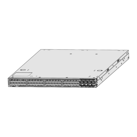
The RG-S6580-48CQ8QC switch is a next-generation switch featuring high-performance, high-density, and low- latency launched by Ruijie Networks for Artificial Intelligence (AI) and other applications. The RG-S6580- 48CQ8QC switch delivers high-density 100GE access, 400GE uplink ports, and diverse data center features. It can be used with Ruijie’s RG-N18000-XH and RG-S6980-64QC switches for a high-performance and high-... -
Page 11: Chassis
Hardware Installation and Reference Guide Overview Chassis The RG-S6580-48CQ8QC hardware system consists of a chassis, a power supply system, and a cooling system. Power supply system: provides two power module slots and supports 1+1 power redundancy. Cooling system: provides six fan module slots and supports 5+1 fan redundancy. - Page 12 Hardware Installation and Reference Guide Overview Table 1-3 Front Panel Components Component System status LED BMC status LED Power status LED Fan status LED Locating LED DSFP port DSFP port LED QSFP-DD port QSFP-DD port LED Asset tag Figure 1-4 Rear Panel Structure Table 1-4 Rear Panel Components...
-
Page 13: Leds
Hardware Installation and Reference Guide Overview 1.3.2 LEDs Table 1-5 LEDs Silkscreen Label Description Solid green: The system is operating normally. Blinking green: The system is starting up. Solid red: ○ The system (including all modules) is not functioning properly. System status ○... -
Page 14: Ports
Hardware Installation and Reference Guide Overview Silkscreen Label Description Solid yellow: The port has made a successful 10/100 Mbps link. Blinking yellow: The port is sending and receiving traffic at Management 10/100 Mbps. LINK/ACT port LED Solid green: The port has made a successful 1,000 Mbps link. Blinking green: The port is sending and receiving traffic at 1,000 Mbps. -
Page 15: Cooling
Range: 9,600 bit/s to 115,200 bit/s ○ Default value: 9,600 bit/s 1.3.4 Cooling The RG-S6580-48CQ8QC adopts the front-to-rear airflow. Air flows in through the ports and out through the power module, as shown in Figure 1-5. Caution Maintain a minimum clearance of 200 mm (7.87 in.) around the equipment for air circulation. -
Page 16: Technical Specifications
Hardware Installation and Reference Guide Overview 1.3.5 Technical Specifications Table 1-7 Technical Specifications Class Item Specification 2.9 GHz quad-core Memory 8 GB, DDR4 (compatible with 32 GB) Technical indicators Flash memory NOR flash: MB (for BootROM) 240 GB Dimensions Without packing materials: 442 mm x 700 mm x 44 mm (17.40 in. - Page 17 Hardware Installation and Reference Guide Overview Class Item Specification Noise Sound pressure level at 27° C(80.6° F): < 78 dB AC power protection Surge protection Common mode: 2 kV Differential mode: 1 kV Power supply mode HVDC Power connector C14 three-pin connector Max: 742 W Power consumption Typical: 633 W...
-
Page 18: Asset Tag
Hardware Installation and Reference Guide Overview Class Item Specification Mean Time to Recovery 0.5 hours (MTTR) Reliability Power redundancy Fan redundancy Hot swapping Hot swappable power and fan modules GB/T 9254.1 Certification Safety standard GB 4943.1 Environment protection Environment protection regulation Warning ... -
Page 19: Power Module
Hardware Installation and Reference Guide Overview Power Module The smart power module for the RG-S6580-48CQ8QC supports power consumption management and hot swapping. It can obtain the output power, output current, and operating temperature in real time. Caution To improve system stability and availability, you are advised to configure 1+1 power redundancy. The chassis configured with power redundancy works in current-sharing mode. - Page 20 Hardware Installation and Reference Guide Overview Table 1-8 Components Component Description Forward fan Handle Handle of the power module Power connector Three-pin connector Latch Latch of the power module Power status LED 2. LED Table 1-9 Silkscreen Description Label Solid green: The power module is outputting power normally. Blinking green at 1 Hz: ○...
-
Page 21: Fan Module
Hardware Installation and Reference Guide Overview Item Specification 13.8 A (100 V AC to 127 V AC) Max. input current range 8.5 A (200 V AC to 240 V AC) 6.5 A (180 V DC to 300 V DC) 83A (100V AC to 127V AC) Rated output current 108A (200V AC to 240V AC) 108A ( 180V DC to 300V DC) - Page 22 Hardware Installation and Reference Guide Overview Figure 1-10 Structure Table 1-11 Components Component Description Handle Handle of the fan module Fan status LED Latch Latch of the Fan module 2. LED Table 1-12 Silkscreen Description Label Solid green: The fan module is operating normally. Fan status Blinking green: The fan module is being initialized.
-
Page 23: Cables
Hardware Installation and Reference Guide Overview 3. Technical Specifications Table 1-13 Technical Specifications Item Specification Without packing materials: 40 mm x 138 mm x 40 mm (1.57 in. x Dimensions (W x D x H) 5.43 in. x 1.57 in.) Weight Without packing materials: 0.15 kg (0.33 lbs.) Number of fans... -
Page 24: Ethernet Cable
The equipment supports automatic MDI/MID-X crossover detection. Both straight through and crossover cables are applicable. 1.6.3 Power Cord 1. Applicable Power Cords Table 1-15 Power Cords Chassis AC/HVDC Power Cord CAB-1.5M-GB-C-10A-B CAB-3M-GB-10A-B CAB-5M-GB-10A-B CAB-2M-IEC-10A-B RG-S6580-48CQ8QC CAB-2M-IEC-10A-Y CAB-3M-IEC-10A-B CAB-3M-IEC-10A-Y CAB-5M-IEC-10A-B... -
Page 25: Grounding Wire
Select power cords according to power modules. Power cords applicable to power modules are subject to update without prior notification. 2. AC/HVDC Power Cord Select power cords based on the types of power sockets used in your equipment room. Ruijie provides the following types of power cords to suit different the power sockets: ... -
Page 26: Pluggable Modules
Caution Always use Ruijie certified pluggable modules. Uncertified pluggable modules may lead to service instability. Ruijie will not claim responsibility for the service problems caused by uncertified pluggable modules or provide a solution. The models of pluggable modules applicable to the chassis are subject to update without prior notification. -
Page 27: Preparing For Installation
Hardware Installation and Reference Guide Preparing for Installation Preparing for Installation Safety Guidelines Note To avoid personal injury or equipment damage, review the safety guidelines in this chapter before you begin the installation. The following safety precautions may not include all the potentially hazardous situations. 2.1.1 General Precautions ... -
Page 28: Preventing Esd Damage
Hardware Installation and Reference Guide Preparing for Installation safety grounds, and moist floors. Locate the emergency power-off switch in the room. In the case of an electrical accident, you will be able to quickly turn off the power. Never assume that power is disconnected from a circuit. -
Page 29: Site Requirements
Hardware Installation and Reference Guide Preparing for Installation Caution If the equipment has been powered off for more than 18 months, power on the equipment and run it for consecutive 24 hours to activate the device. Site Requirements The equipment must be installed indoors for normal operation and prolonged service life. The following sections provide specific information to help you plan for a proper operating environment. -
Page 30: Cleanliness
Hardware Installation and Reference Guide Preparing for Installation loosening. Furthermore, internal circuits are prone to static electricity. Table 1-8 Technical Specifications for the humidity requirement. Note The operating humidity is measured at the point that is 1.5 m (4.92 ft.) above the floor and 0.4 m (1.31 ft.) before the equipment with no protective plates in front or at the back of the equipment. -
Page 31: System Grounding
Hardware Installation and Reference Guide Preparing for Installation Note The average value is measured over one week. The maximum value is the upper limit of the harmful gas measured in one week for up to 30 minutes every day. 2.2.7 System Grounding A reliable grounding system is the basis for stable and reliable operation, which is indispensable for preventing lightning strikes and interference. -
Page 32: Preventing Electromagnetic Interference
Hardware Installation and Reference Guide Preparing for Installation Figure 2-1 Grounding Stud 2.2.8 Preventing Electromagnetic Interference Electromagnetic interference mainly comes from outside the equipment or application system and affects the equipment through capacitive coupling, inductive coupling, electromagnetic waves, and other conduction modes. ... -
Page 33: Tools
Hardware Installation and Reference Guide Preparing for Installation Figure 2-2 19-Inch Rack (1) Use a four-post 19-inch EIA rack. (2) The left and right square hole rack posts are 465 mm (18.31 in.) apart. (3) The square hole rack post is at least 180 mm (7.09 in.) from the front door, and the front door is at most 25 mm (0.98 in.) thick. -
Page 34: Unpacking The Switch
Hardware Installation and Reference Guide Preparing for Installation Unpacking the Switch 2.5.1 Verifying the Shipped Content Table 2-4 Default Shipping Container Components Description Chassis, yellow-green grounding wire, Quick Start Guide, Package Contents, Chassis kit and documentation Module kit Modules, Package Contents, and Quick Start Guide Note The preceding items are delivered against the purchase contact. - Page 35 Hardware Installation and Reference Guide Preparing for Installation Figure 2-4 Take out the accessory box, verify that the main accessories are not missing, and then keep the accessory box handy. Figure 2-5 Figure 2-6 Place the switch with the panel foam facing upwards. Remove the panel foam and set it aside.
-
Page 36: Installing The Switch
Hardware Installation and Reference Guide Installing the Switch (7) Remove the tape on the static-shielding container, open and reach into the bag with both hands, grab the two sides of the chassis, lift the switch out of the static-shielding container, and place it on an antistatic workbench. -
Page 37: Installation Procedure
Hardware Installation and Reference Guide Installing the Switch Installation Procedure Figure 3-1 Installation Procedure Start Prepare Install the chassis. Connect the grounding wire. Install the power module. Connect the power cord. Verify installation. Set the power Troubleshoot switch to ON. Set the power Normal? switch to OFF. -
Page 38: Installing The Rack
Hardware Installation and Reference Guide Installing the Switch Verifying Installation Connecting the Power Cord Installing the Rack 3.2.1 Installation Guidelines Make sure the following guidelines are met: All expansion bolts for securing the rack base to the ground are installed from bottom to up in the sequence of large flat washer, spring washer, and nut, and the installation holes on the base are flush with the expansion bolts. -
Page 39: Mounting The Brackets
Hardware Installation and Reference Guide Installing the Switch door. As a result, the front door cannot be closed after Ethernet cables and optical fibers are connected to the chassis. Generally, maintain a minimum clearance of 10 mm (0.39 in.) between the front panel and the front door. -
Page 40: Installing The Protective Grounding Wire
Hardware Installation and Reference Guide Installing the Switch Caution Install the L-bracket by driving screws into the four among six screw holes on each side. Distinguish left and right rack-mount guide rails according to the notations. The rack-mount guide rails delivered with the chassis are applicable to a cabinet with a depth ranging from 800 mm (31.50 in.) to 1,200 mm (47.24 in.). -
Page 41: Installing And Removing The Fan Module
Hardware Installation and Reference Guide Installing the Switch (2) Crimp the other end to the grounding terminal of the rack or the grounding bar of the equipment room. Bundle the grounding wire individually for easy replacement. Danger ● To ensure personal and equipment safety, it is necessary to ground the switch properly. The resistance between the chassis and the ground must be less than 0.1-ohm. -
Page 42: Installing The Fan Module
Hardware Installation and Reference Guide Installing the Switch 3.5.1 Installing the Fan Module (1) Remove a fan module from its packing materials. (2) Hold the fan module by its handle. Position the fan module in front of the open fan slot. Slide the fan module all the way into the slot until the module plugs into the receptacle at the back of the slot. -
Page 43: Installing And Removing The Power Module
Hardware Installation and Reference Guide Installing the Switch Warning Pull the fan module out of the slot gently. If the fan module slot is to remain empty, install a filler panel to allow for adequate airflow and to keep dust out of the chassis. -
Page 44: Removing The Power Module
Hardware Installation and Reference Guide Installing the Switch Figure 3-7 Securing the Power Cord Warning Slide the power module all the way into the chassis gently. Align the power module in the right orientation to the open power slot. ... -
Page 45: Installing The Pluggable Module
Make sure that you have mounted the chassis on the rack before installing the pluggable module. For procedure, see Ruijie Optical Module Hardware Installation and Reference Guide for details. The documentation is subject to update without prior notification. Please access Ruijie Networks at https://www.ruijienetworks.com/... -
Page 46: Commissioning
Hardware Installation and Reference Guide Commissioning (1) Connect one end of the AC power cord to the power connector. (2) Connect the other end of the AC power cord to the power socket of the external power system. Caution Make sure the power socket is OFF before connecting the power cord. - Page 47 Hardware Installation and Reference Guide Commissioning Click Serial in the left column. Set Bits per second to 115,200, Data bits to 8, Parity to None, Stop bits to 1, and Flow control to None. Click Open to set up the connection.
-
Page 48: Powering On The Device
Hardware Installation and Reference Guide Commissioning (4) After setting up the configuration environment, power on the device. If the device is already configured with a password, a notification will appear. Click Accept, and enter your username and password for connection. Powering on the Device 4.2.1 Checklist Before Power-on... -
Page 49: Monitoring And Maintenance
Hardware Installation and Reference Guide Monitoring and Maintenance Monitoring and Maintenance Monitoring 5.1.1 Monitoring the LEDs Each module installed in the chassis features a LED, which can be used to monitor the status of each module while the switch is running. See 1 Overview for details. -
Page 50: Replacing The Fan Module
Hardware Installation and Reference Guide Monitoring and Maintenance Caution After hot swapping a power module, wait for at least 30 seconds before proceeding with next hot swapping operation. Make sure that the chassis is secured to avoid the chassis falling down during power module swapping. ... -
Page 51: Troubleshooting
Hardware Installation and Reference Guide Troubleshooting Troubleshooting Flowchart The equipment is not working properly. Check whether the rack is installed properly. Check whether the chassis is mounted on the rack properly. Check whether the power cord is connected properly. Check whether the power module is installed properly. -
Page 52: Common Issues
Hardware Installation and Reference Guide Troubleshooting Common Issues 6.2.1 Forgetting Login Password Symptom The login password is forgotten. Handling Method Contact technical support team. 6.2.2 AC Power Module Failure Symptom All LEDs on the front panel are off. The fan status LED is off, and the fan does not rotate. Handling Method Unplug the power cord from the power module. -
Page 53: Optical Port Linkdown
Hardware Installation and Reference Guide Appendix 6.2.6 Optical Port Linkdown Symptom The system runs normally. After you insert an optical transceiver into an optical port and plug in an optical cable, the link cannot be set up. Handling Method Check whether the receive and transmit ends are reversed. The transmit end of an optical port must be connected to the receive end of the peer port. -
Page 54: Label Contents
Hardware Installation and Reference Guide Appendix Figure 7-1 Keeping the Label Text Area Facing Right or Downwards (2) Labeling procedure Figure 7-2 Signal Cable Labeling Procedure 7.1.3 Label Contents The contents of the two sides of the label identify the location of the ports connected to the two ends of the power cord. -
Page 55: Connectors And Media
Hardware Installation and Reference Guide Appendix Figure 7-3 Signal Cable Label Connectors and Media 7.2.1 100BASE-TX/10BASE-T Port Table 7-1 100BASE-TX/10BASE-T Pin Assignment MDI Mode MDI-X Mode Output Transmit Data+ Input Receive Data+ Output Transmit Data– Input Receive Data-– Input Receive Data+ Output Transmit Data+ Input Receive Data–... - Page 56 Hardware Installation and Reference Guide Appendix for data transmission. Figure 7-5 shows the twisted pair connection for the 1000BASE-T port. The connection method and signal description are provided considering self-made cables. Keep the side without the RJ45 locking clip facing yourself. The signal cables are numbered 1 to 8 from left to right. Figure 7-5 Cable Connection Modes and Signals Table 7-2...
-
Page 57: Surge Protection
Hardware Installation and Reference Guide Appendix Figure 7-6 1000BASE-T Twisted Pair Connections Surge Protection 7.3.1 Installing an AC Power Arrester When an AC power cord from outdoors is directly plugged into the power port of the switch, the AC power connector must be connected to an external surge protector power strip to protect the switch against lightning strikes. -
Page 58: Installing An Ethernet Port Arrester
Hardware Installation and Reference Guide Appendix Figure 7-7 Power Arrester Note The power arrester does not come with the equipment. Please purchase it based on actual requirements. Important points: Make sure that the PE terminal of the power arrester is well grounded. ... - Page 59 Hardware Installation and Reference Guide Appendix (1) Tear one side of the protective paper for the double-sided adhesive tape and paste the tape to the enclosure of the Ethernet port arrester. Tear the other side of the protective paper for the double-sided adhesive tape and paste the Ethernet port arrester to the switch enclosure.
-
Page 60: Site Selection
Hardware Installation and Reference Guide Appendix Site Selection The equipment room should be at least 5 km (16,404.20 ft.) away from heavy pollution sources, such as the smelter works, coal mine, and thermal power plant. The equipment room should be at least 3.7 km (12,139.11 ft.) away from medium pollution sources, such as the chemical factory, rubber factory, and electroplating... - Page 61 Hardware Installation and Reference Guide Appendix cords are routed beside the rack, and top cabling or bottom cabling is adopted according to the locations of the DC power distribution box, AC power socket, or surge protection box in the equipment room. ...
- Page 62 Hardware Installation and Reference Guide Appendix corners. The metal hole traversed by cables should have a smooth and fully rounding surface or an insulated lining. Use cable ties to bundle up cables properly. Please do not connect two or more cable ties to bundle up cables. ...
- Page 63 Hardware Installation and Reference Guide Appendix For the cable terminals fastened by screw threads, tighten the bolt or screw and take cable retention measures, as shown in Figure 7-12. Figure 7-12 Cable Fastening Hard power cords should be fastened in the terminal connection area to prevent stress on terminal connection and cable.
Need help?
Do you have a question about the RG-S6580-48CQ8QC and is the answer not in the manual?
Questions and answers