Ruijie RG-S6250-48XS8CQ Hardware Installation
Hide thumbs
Also See for RG-S6250-48XS8CQ:
- Hardware installation and reference manual (47 pages) ,
- Hardware installation and reference manual (85 pages)

Subscribe to Our Youtube Channel
Related Manuals for Ruijie RG-S6250-48XS8CQ


Summary of Contents for Ruijie RG-S6250-48XS8CQ
- Page 1 Ruijie RG-S6250-48XS8CQ Switch Hardware Installation and Reference Guide Document Version: V1.0 Date: 2022.06.09 Copyright © 2022 Ruijie Networks...
- Page 2 All rights are reserved in this document and this statement. Any reproduction, excerption, backup, modification, transmission, translation or commercial use of this document or any portion of this document, in any form or by any means, without the prior written consent of Ruijie Networks is prohibited.
- Page 3 Preface Intended Audience This document is intended for: Network engineers Technical support and servicing engineers Network administrators Technical Support Ruijie Networks Website: https://www.ruijienetworks.com/ Technical Support Website: https://ruijienetworks.com/support Case Portal: https://caseportal.ruijienetworks.com Community: https://community.ruijienetworks.com ...
- Page 4 Warning An alert that calls attention to important rules and information that if not understood or followed can result in data loss or equipment damage. Caution An alert that calls attention to essential information that if not understood or followed can result in function failure or performance degradation.
-
Page 5: Product Overview
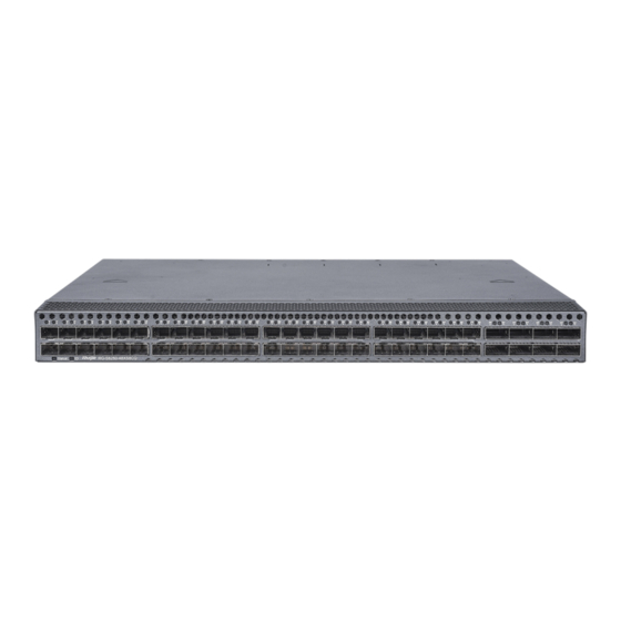
RG-S6250-48XS8CQ is a high density 10GE/25GE data center access switch, featuring 10GE/100GE access, low latency, and complete data center features . RG-S6250-48XS8CQ switch, with up to 48 10GE ports and eight 100GE ports, can be used with S6250-48XS8CQ switch to compose a high-performance and high-reliability data center network. - Page 6 442 mm x 387 mm x 44 mm (17.40 in. x 15.24 in. x 1.73 in.), 1 RU (W x D x H) RG-S6250-48XS8CQ switch is a class A product. Operation of this equipment in a residential environment could cause radio interference, in which case the user may be required to take adequate measures.
- Page 7 Hardware Installation and Reference Guide Product Overview Front Panel Figure 1-2 Front Panel System Status LED SFP+ Port LED Locator LED QSFP28 Port SFP+ Port QSFP28 Port LED The S6250-48XS8CQ switch supports the 100GE QSFP28 module and 10GE SFP+ module. Back Panel Figure 1-3 Back Panel Power Module Slot...
- Page 8 To protect data and avoid equipment damage, use a qualified USB flash drive. The USB port is compatible with most USB flash drives and may fail to identify some brands. The RG-S6250-48XS8CQ switch supports commissioning, configuration, maintenance, management and program uploading through the console port.
- Page 9 At least one power module is required. If any slot is unoccupied, install a filler panel to enable proper airflow. Heat Dissipation The working temperature of the RG-S6250-48XS8CQ switch ranges from 0° C to 45° C (32° F to 113° F). The heat dissipation design needs to ensure equipment stability, safety and maintainability in such an environment. The RG- S6250-48XS8CQ switch adopts fan ventilation and enforced convection to ensure the equipment can work normally in the specified environment.
- Page 10 Hardware Installation and Reference Guide Product Overview Maintain a minimum clearance of 20 cm (7.87 in.) around the chassis for ventilation. At least three fan modules are required. If any slot is unoccupied, install a filler panel to enable proper airflow and avoid dust.
-
Page 11: Preparing For Installation
Hardware Installation and Reference Guide Preparing for Installation 2 Preparing for Installation 2.1 Safety Precautions To avoid personal injury and equipment damage, carefully read the safety precautions before you install the switch. The following safety precautions may not cover all possible dangers. 2.1.1 Installation ... -
Page 12: Installation Site Requirements
Hardware Installation and Reference Guide Preparing for Installation Make sure that the equipment is powered off when you cut off the power supply. Do not place the switch in a wet position, and keep the switch away from liquid. Any nonstandard and inaccurate operation can cause an accident such as fire or electrical attack, thus causing severe damages to human bodies and equipment. -
Page 13: Temperature And Humidity
Model Working Temperature Working Humidity RG-S6250-48XS8CQ 0º C to 45º C (32º F to 113º F) 10% to 90% (non-condensing) The ambient temperature and humidity of the switch are measured at the point that is 1.5 m (59.06 in.) above the floor and 0.4 m (15.75 in.) before the rack when there is no protective plate in the front or at the back of the rack. - Page 14 Hardware Installation and Reference Guide Preparing for Installation The Average refers to the average limit of harmful gas in one week. The Maximum value is the upper limit of the harmful gas measured in one week for up to 30 minutes every day. 2.2.5 Grounding A proper grounding system is the basis for stable and reliable running and is indispensable for preventing lightning strikes and interference.
-
Page 15: Fiber Connections
Hardware Installation and Reference Guide Preparing for Installation Electromagnetic interference (EMI) occurs due to electromagnetic radiation or conduction, depending on the transmission path. When the energy, often RF energy, from a component arrives at a sensitive component via the space, the energy is known as radiated interference. - Page 16 Hardware Installation and Reference Guide Preparing for Installation 1. Cut off the packing tape of the shipping container with scissors, place it on a flat surface with the shipping container facing upward, and check whether the seal on its top surface is intact. 2.
-
Page 17: Installing The Switch
Hardware Installation and Reference Guide Installing the Switch 3 Installing the Switch The switch must be installed indoors. Make sure that requirements in Chapter 2 are all met. 3.1 Installation Procedure - 16 -... -
Page 18: Before You Begin
Hardware Installation and Reference Guide Installing the Switch Prepare for installation Prepare for installation Install the rack Mount the switch into the rack Ground the switch Turn on the power Install the modules Connect the cables Bundle the cables Verify the installation 3.2 Before You Begin Confirm the following before installation: - 17 -... -
Page 19: Mounting The Cabinet
Hardware Installation and Reference Guide Installing the Switch The installation site provides sufficient space for heat dissipation. The installation site meets the temperature and humidity requirements of the switch. The power supply and required current are available in the installation site. ... -
Page 20: Mounting The Brackets
Hardware Installation and Reference Guide Installing the Switch Before installing the switch in a cabinet, please check whether the racks are properly positioned. If the racks are too close to the front door of the cabinet, you may not be able to close the front door after plugging in the Ethernet and fiber cables . The front panel of the switch should be at least 10 mm (0.39 in.) away from the front door of the cabinet. -
Page 21: Mounting The Switch On A Workbench
Hardware Installation and Reference Guide Installing the Switch Install a mounting bracket by driving four screws into the four among the six screw holes on each side of the panel. Distinguish left and right rack-mount guides according to the marked orientation. The rack-mount guides are only applicable for a rack with a depth ranging from 800 mm (31.50 in.) to 1200 mm (47.24 in.). -
Page 22: Installing And Removing A Fan Module
Hardware Installation and Reference Guide Installing the Switch 3.5 Installing and Removing a Fan Module Wear an anti-static wrist strap before the following operations. Installing a Fan Module Take a fan module from its packing materials. Grasp the handle and slide the module into the slot along the guide rail until you feel the connector snap into place. Tighten the captive screws to secure the fan module in the chassis. - Page 23 Hardware Installation and Reference Guide Installing the Switch Figure 3-5 Removing a Fan Module Pull the M1EFAN II-F or M1EFAN II-R fan module out of the slot gently. Install a filler panel in the unoccupied slot to ensure adequate airflow and avoid dust in the chassis. 3.6 Installing and Removing a Power Module Wear an anti-static wrist strap before the following operations.
- Page 24 Hardware Installation and Reference Guide Installing the Switch Installing Power Cord Retainer Remove the power cord retainer from its packing materials. The power cord retainer consists of a retainer strip and a flexible retainer clamp. Both the strip and the clamp have two sides, one side smooth and the other side grooved. The power cord retainer has two latches.
- Page 25 Hardware Installation and Reference Guide Installing the Switch Removing a Power Module Adjust the clamp to remove the power cord. Press the latch on the module and grasp the handle with one hand. Place your other hand under the module to support its weight. Pull the power module out of the slot gently. Install the filler panel in the empty slot.
- Page 26 Hardware Installation and Reference Guide Installing the Switch Remove the power module from its packing materials and make sure the input specifications meet requirements. Remove the filler panel covering the slot. Keep the module nameplate face upward. Grasp the handle with one hand and place your other hand under the power module to support its weight.
- Page 27 Hardware Installation and Reference Guide Installing the Switch If you find it difficult to fully insert the power module, pull the power module out, align it to the guide rails and slide it into the slot again. The power modules and fan modules with different airflow directions cannot be used together. Removing a Power Module Adjust the clamp to remove the power cord.
- Page 28 Hardware Installation and Reference Guide Installing the Switch (2) Power supply B (The input terminals are deep blue. They are the -48 V terminal, the RTN terminal and the PGND terminal from top to bottom .) matches power cord B (HST-RJ-250, the sequence of the colored wires from top to bottom: black-red-yellow/green).
-
Page 29: Connecting The Console Port
Hardware Installation and Reference Guide Installing the Switch Figure 3-15 Removing a Power Module Pull the power module out of the slot gently. Install the filler panel in the empty slot to allow for adequate airflow and keep out dust. 3.7 Connecting a Grounding Cable Connect the PGND to the grounding lug of the rack and then connect the grounding lug to the grounding bar of the equipment room. -
Page 30: Connecting The Management Port
Hardware Installation and Reference Guide Installing the Switch By default, the baud rate is 9600, data bit 8, parity check none, stop bit 1, and flow control none. 3.9 Connecting the Management Port Precautions Distinguish single-mode and multi-mode optical fibers and ports. ... - Page 31 Hardware Installation and Reference Guide Installing the Switch Verifying Cable Connection The UTP and STP cables match with the interface type. Cables are properly bundled. Grounding cables are connected properly and observe the requirement. All cables are routed indoors. If not, check whether the power supply and interfaces are protected from lightning strikes.
-
Page 32: System Commissioning
Hardware Installation and Reference Guide System Commissioning 4 System Commissioning 4.1 Setting Up the Configuration Environment Setting Up the Configuration Environment Connect the PC to the console port of the switch through the Ethernet cable. Figure 4-1 Configuration Environment Connecting the Ethernet Cable ... - Page 33 Hardware Installation and Reference Guide System Commissioning In the Name box, enter the new connection name and click OK. The Connect to dialog will appear. From the Connect using drop-down list, select a COM port.错误!未找到引用源。Figure 4-3 Click OK. The COM1 Properties dialog box will appear. Select the following settings: Bits per second: 9600; Data bits: 8;...
-
Page 34: Powering On The Switch
Hardware Installation and Reference Guide System Commissioning Click OK and the HyperTerminal window will appear. 4.2 Powering On the Switch Checklist before Power-On The switch is fully grounded. The fan module and the power module are properly installed. ... - Page 35 Hardware Installation and Reference Guide System Commissioning The Ethernet cable is properly connected. The terminal (it can be a PC) used for configuration is already started. The parameters are already configured. Checklist after Power-On (Recommended) After power-on, check the following: ...
-
Page 36: Monitoring And Maintenance
Hardware Installation and Reference Guide Monitoring and Maintenance 5 Monitoring and Maintenance 5.1 Monitoring Indicator When the switch is running, you can monitor the module status by observing the LED. If the Status LED is red, it indicates that the system is not functioning properly. Log in to the software management system to troubleshoot the fault. - Page 37 Hardware Installation and Reference Guide Monitoring and Maintenance To replace fuses, contact technical support. - 36 -...
-
Page 38: Troubleshooting Flowchart
Check the installation of other modules Check the LEDs on the device Check serial port connection and parameters Check the cable connection Contact Technical Support of Ruijie Networks 6.2 Common Troubleshooting Procedures Fault 1: The login password is forgotten. Fault Symptom The login password is forgotten. - Page 39 Hardware Installation and Reference Guide Troubleshooting Handling Method Contact technical support. Fault 2: The AC power module does not work. Fault Symptom All LEDs on the front panel are off. The fan status LED is off, and the fan does not rotate. The power supply status LED is off.
- Page 40 Hardware Installation and Reference Guide Troubleshooting Fault Symptom The system runs normally. After you insert an optical transceiver into an optical port and plug in a fiber cable, the link cannot be set up. Handling Method Check whether the receive and transmit ends are reversed. The transm it end of an optical port must be connected to the receive end at the other end.
- Page 41 Hardware Installation and Reference Guide Appendix 7 Appendix 7.1 Connectors and Media 10GBASE-T/1000BASE-T/100BAS E-TX Port The 1000BASE-T/100BASE-TX/10BASE-T is a 10/100/1000 Mbps auto-negotiation port that supports auto MDI/MDIX Crossover. The 10GBASE-T port complies with the IEEE 802.3an standard, and uses four pairs of connected wires for transmission. The following table shows the connection of the twisted pairs used by the 10GBASE -T port.
- Page 42 Hardware Installation and Reference Guide Appendix The 1000BASE-T port complies with the IEEE 802.3ab standard, and uses 100-ohm CAT5, CAT5E or cables with a higher standard for transmission over a distance reach of up to 100 meters . The 1000BASE-T port requires four pairs of connected wires for transmission.
- Page 43 Hardware Installation and Reference Guide Appendix - 42 -...
- Page 44 Hardware Installation and Reference Guide Appendix 7.2 Mini-GBIC, 10GE, 25GE, 40GE, and 100GE Modules We provide Mini-GBIC modules, 10GE SFP+ modules, 40GE QSFP+ modules, 100GE QSFP28 modules, and AOC cables according to the port types . You can select modules to suit your specific needs. The following models and technical specifications are listed for your reference.
- Page 45 Hardware Installation and Reference Guide Appendix MINI-GBIC-ZX80-SM1550 80 km MINI-GBIC-ZX100-SM1550 100 km Models and Technical Specifications of 10GE SFP+ Modules Existing 10GE SFP+ modules: Intensity of Intensity of Modular Core Transmitted Received Wavelength Bandwidt Model Fiber Type Size Cabling (nm) Light (dbm) Light (dbm) (μm)
- Page 46 Hardware Installation and Reference Guide Appendix (OM4) 300m 2000 -9.9 to 40G-QSFP- (OM3) -7.6 to 2.3 (MPO LSR-MM850 400m (Perlane) connector) (Perlane) 4700 (OM4) -13.7 to 40G-QSFP- -7.0 to 2.3 1310 10km LR4-SM1310 (Perlane) (Perlane) Existing 40GE QSFP+ AOC cables: Copper Conductor Support...
-
Page 47: Surge Protection
Hardware Installation and Reference Guide Appendix 7.3 Surge Protection Installing AC Power Arrester (Surge Protection Power Strip) The AC power port must be connected to an external surge protection power strip to prevent the switch from being struck by lightning when the AC power cord is introduced from the outdoor and directly connected to the power port of the switch. - Page 48 Hardware Installation and Reference Guide Appendix Installing the Ethernet Port Arrester Please connect an Ethernet port arrester to the switch to prevent the damage by lightning before connecting an outdoor Ethernet cable to the switch. Tools: Phillips screwdrivers or flat-head screwdriver, multimeter, and diagonal pliers Installation Steps: Tear one side of the protective paper for the double-sided adhesive tape and paste the tape to the housing of the Ethernet port arrester.
- Page 49 Hardware Installation and Reference Guide Appendix Reversed installation direction of the arrester. Connect the external Ethernet cable to the IN end and connect the Ethernet port of the switch to the OUT end. Poor grounding of the arrester. The ground cable of the arrester should be as short as possible to ensure that it is in good contact with the ground terminal of the switch.
-
Page 50: Cabling Recommendations
Hardware Installation and Reference Guide Appendix 7.4 Cabling Recommendations When the switch is installed in a standard 19-inch rack, secure the cables around the cable management brackets. Top cabling or bottom cabling is adopted according to the actual situation in the equipment room. All transferred cable connectors should be placed at the bottom of the rack in an orderly manner instead of outside the rack that is easy to touch. - Page 51 Hardware Installation and Reference Guide Appendix Cables of different types (such as power cords, signal cables, and ground cables) should be separated in c abling and bundling. Mixed bundling is disallowed. When they are close to each other, it is recommended to adopt crossover cabling.
- Page 52 Hardware Installation and Reference Guide Appendix Figure 7-9 Bundling Up Cables (3) Cables not to be assembled or remaining parts of cables should be folded and placed in a proper position of the rack or cable trough. The proper position refers to a position that does not affect switch performance or damage the switch or cable.
- Page 53 Hardware Installation and Reference Guide Appendix Figure 7-10 Cable Fastening Hard power cords should be fastened in the terminal connection area to prevent stress on terminal connection and cable. Do not use self-tapping screws to fasten terminals. Power cords of the same type and in the same cabling direction should be bundled up into cable bunches, with cables in cable bunches clean and straight.
-
Page 54: Site Selection
Hardware Installation and Reference Guide Appendix 7.5 Site Selection The equipment room should be at least 5 km away from heavy pollution sources, such as the smelter works, coal mine, and thermal power plant. The equipment room should be at least 3.7 km away from medium pollution sources, such as the chemical factory, rubber factory, and electroplating factory.
Need help?
Do you have a question about the RG-S6250-48XS8CQ and is the answer not in the manual?
Questions and answers