Table of Contents
Advertisement
Quick Links
Bluekit Downloads
AIO Basic
en Original instructions
Product overview and mounting . . . . . . . . . . . . . . Page. . . . . 3-19
Connection and setup. . . . . . . . . . . . . . . . . . . . . . Page. . . . 20-25
Maintenance . . . . . . . . . . . . . . . . . . . . . . . . . . . . . Page. . . . 26-29
Troubleshooting . . . . . . . . . . . . . . . . . . . . . . . . . . Page. . . . 30-36
Mounting material . . . . . . . . . . . . . . . . . . . . . . . . . Page . . . . . . 37
99.829.07 1.2/06/23
Advertisement
Table of Contents
Troubleshooting

Related Manuals for D+H BlueKit AIO Basic


Summary of Contents for D+H BlueKit AIO Basic
- Page 1 Bluekit Downloads AIO Basic en Original instructions Product overview and mounting ....Page..3-19 Connection and setup..... . Page..20-25 Maintenance .
-
Page 2: Table Of Contents
Table of contents Product overview and mounting Intended use .............................3 Safety notes ..............................3 Application example..........................3 System components overview ........................4 System components description .......................5 Overview control panel - CPL-B........................6 LED indicators- CPL-B..........................7 RJ45 connections and status LEDs ......................7 DIP switch settings - CPL-B........................8 Technical Data - CPL-B..........................9 Declaration of Conformity .........................9 Service timer .............................9... -
Page 3: Intended Use
- Only for inside mounting Save all warnings and instructions for future - Just use unchanged original D+H parts reference. Caution Falling Hazard! - Always secure ventilation elements properly against falling down the shaft. -
Page 4: System Components Overview
System components overview JK-180 JK-190 ALAS SD-L-F1 PD-RJ-AIO-P&G PD-RJ-AIO-End CPL-B PD-RJ-AIO-HE RT 45/O-L-RJ LST-CO2 RT 45/O-RJ TS-RJ SLT 42-U-SD-RJ RTR 231-RJ CWSO-RR-S1-RJ 4/40 AIO Basic English 99.829.07 1.2/06/23... -
Page 5: System Components Description
System components description 1. Ventilation flap (SHEV) • Cutting back on energy losses thanks to closure of the opening in the lift shaft. • Ventilates and extracts smoke when necessary. • For vertical or horizontal installation. • Depending on the building type, with or without weather protection JK-180 - Ventilation flap with spring return motor with mounting frame for integrated installation JK-190 - Ventilation flap with spring return motor for surface mounting 2. -
Page 6: Overview Control Panel - Cpl-B
Overview control panel - CPL-B Antenna Spare fuse in cover F0,63 A Mains connection Reset button with transport lock Temperature sensor Connections via RJ45 plugs with LED Status indicators DIP switch Teach LED indicators Button button (internal) Reset line ON/OFF Signal emitter Fuse... -
Page 7: Led Indicators- Cpl-B
LED indicators- CPL-B 2 3 4 5 6 LED 1 Radio communication LED 2 CPU fault CPL-B (yellow) LED 3 CPL-B OK (green) LED 4 LST-VOC fault (yellow) LED 5 Service timer (yellow) LED 6 Mains (green) RJ45 connections and status LEDs COM 1 COM 2 24 V... -
Page 8: Dip Switch Settings - Cpl-B
DIP switch settings - CPL-B DIP switch S1 Factory setting S1.1 Alarm delay, shaft group (60 s) S1.2 Shaft group: Ventilation time limitation S1.3 Shaft group: Group fault = alarm S1.4 Line port 1 shaft detector: Active S1.5 Port 2 FAS: Active S1.6 Button: Active S1.7 Line fault = alarm Factory settings... -
Page 9: Technical Data - Cpl-B
Plastic (Polycarbonate) Colour white Dimensions WxHxD 172 x 151 x 95 mm * D+H Highspeed (HS) drives will be supported. Declaration of Conformity Service timer We declare under our sole responsibility that the An overdue maintenance of the system will be product described under “Technical Data”... -
Page 10: Mounting - Weather Protection Hvc, Hvl, Alas
Mounting - Weather protection HVC, HVL, ALAS If there is no weather protection in front Weather protection roof cover Louvre cover of the ventilation opening on site, appropriate weather protection must be correctly attached to the outer shell of the building. The ALAS grille can be guided through the wall opening from the inside and inserted into the opening. -
Page 11: Mounting - Ventilation Flap Jk 180, Jk 190
Mounting - Ventilation flap JK 180, JK 190 HVC / HVL HVC / HVL min. 20 cm JK 180 JK 180 Standard mounting JK-180: The ventilation flap is inserted into the ceiling or wall from the inside. If the existing opening is too small, the ventilation flap with motor can also be installed facing into the shaft. -
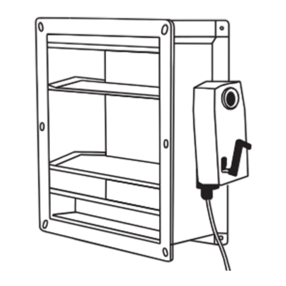
Page 12: Mounting - Control Unit Cpl-B
Mounting - Control unit CPL-B Place the central unit at eye level on the wall in the shaft head (highest cabin position). Fasten the mounting brackets for rear ventilation with self-tapping screws. Terminals at the bottom, status LEDs must be clearly visible Align temperature sensor Fastening materials:... -
Page 13: Mounting - Infrared Detector Sd-L-F1
Mounting - Infrared detector SD-L-F1 max. 45 cm The smoke detection system with optical infrared below the beam SD-L-F1 consists of 2 components: shaft ceiling - Infrared detector: installed in the shaft head and connected to the central unit of the ventilation system, sends infrared beam to the reflector in the shaft pit. -
Page 14: Initialisation - Sd-L-F1
Initialisation - SD-L-F1 - First, roughly align the infrared beam with the reflector using the laser. - Slide the slide switch to the left (Align) to switch on the laser. - Use navigation buttons to adjust the laser dot on the reflector. - Move the slide switch to the right (Operate) to start the automatic alignment of the infrared beam. -
Page 15: Mounting - Smoke Vent Button Rt 45-L-Rj / Rt 45-Rj
Mounting - Smoke vent button RT 45-L-RJ / RT 45-RJ - The smoke vent button (RT 45L-RJ / RT 45-RJ) can be used to initiate manual venting and reset an alarm. - Up to 8 smoke vent buttons can be connected in series. -
Page 16: Mounting - Lift Status Transmitter Lst-Co2
Mounting - Lift Status Transmitter LST-CO2 The LST-CO2 is used to detect and report the use of the lift (breakdown, maintenance, movement), the presence of passengers in the cabin by pressing the emergency call button and to monitor the CO2 content, humidity and air temperature at the cabin. The resulting need for ventilation is reported to the central unit via radio link. -
Page 17: Dip Switch Settings - Lst-Co2
DIP switch settings - LST-CO2 DIP switch S3 Factory setting S3.1 Monitoring the emergency call button input S3.2 Parameterisation of the connected central unit S3.3 Temperature monitoring Factory settings S3.4 Humidity monitoring S3.5 Monitoring of the CO2 level S3.6 Threshold value for temperature monitoring ON = 32 °C, OFF = 28 °C S3.7 Threshold value for humidity... -
Page 18: Technical Data - Lst-Co2
Technical Data - LST-CO2 Power supply 230 V AC, 50 Hz (195 ... 253 V AC) Rated power 9,2 VA Rel. humidity (operation) 20 %RH ... 90 %RH Temperature range -5 °C ... +40 °C Ingress protection IP 32 Protection class Ventilation connection max. -
Page 19: Identifying A Lift Fault With Trapped Persons
Identifying a lift fault with trapped persons As a rule, if the emergency call button in the car is pressed, it is frequently possible to tap into emergency potential on the car roof, often as feed voltage for an emergency bell that is routed to the LST-CO2 by an RJ11 patch cable. -
Page 20: Connection - Rj45 Sockets
Connection - RJ45 sockets All components are connected to the central unit via RJ45 cables and connectors. Patch cable 4x2 AWG26 COM 1 COM 2 24 V RJ45 - RJ45 connector T-568B brown white/brown green white/green orange white/orange blue white/blue RJ45 - screw terminal adapter (only connect to CPL-B with RJ45 connector and patch cable) Corrosion protection:... -
Page 21: Connection - 230 V Power Supply
Connection - 230 V power supply 230 V, 50 Hz Seperate electric circuit. Mark fuse. Release opening for mains plug Connection - M1 output Connection of on-site 24 V spring return motor On-site spring return motors can be connected to the CPL-B using COM 1 COM 2 24 V... -
Page 22: Connection - General Status Signals Com 1
Connection - General status signals COM 1 Output of various status signals via potential-free contacts in the CPL-B. COM 1 COM 2 24 V Output - fault signal: Adjustable via DIP switches S2.1 and S2.2.Potential-free contact in the central unit closes in the case of a fault. The contact is open in the case of a power failure. -
Page 23: Connection - Lift Shaft Control Com 2
Connection - Lift shaft control COM 2 Connection to the lift controller for incoming and outgoing signals. COM 1 COM 2 24 V Output - alarm transmitter 24 V DC: For connecting optical or acoustic alarm transmitters (flashing light, siren, etc.). Output - Fault / Alarm: Output of a fault or an alarm via a potential-free changeover contact. -
Page 24: Connection - Fas Input
Connection - FAS input Connection to fire alarm system The central unit can be controlled by an on-site fire alarm system. COM 1 COM 2 24 V (DIP switch S1.5 = "ON"). If the lift shaft is only monitored by fire detectors of the fire alarm system, e.g. -
Page 25: Blower Door Test
Blower Door Test Disposal To perform and during a blower door test, a Electrical devices, accessories, batteries and packa- permanent closure of the ventilation element is ging should be sorted for environmental-friendly required. recycling. Do not dispose electrical devices and To guarantee the closure of the ventilation batteries into household waste! element, carry out the following steps:... -
Page 26: Maintenance
Inspection and maintenance has to be carried out according to D+H maintenance notes. Only original D+H spare parts may be used. Repair is to be carried out exclusively by D+H. Maintenance work is only allowed when the device is in a de-energized condition! Wipe away debris or contamination with a dry, soft cloth. -
Page 27: Status Indicators (Maintenance Level 1)
Status indicators (maintenance level 1) COM 1 COM 2 24 V Maintenance level ON (Flashing 1x Level 1) (Flashing 2x Level 2) Function test - Ventilation elements JK-180 / JK-190 1. Check ventilation element louvres have closed and are airtight (visual JK-180 inspection). -
Page 28: Function Test - Smoke Detector Sd-L-F1
Function test - Smoke detector SD-L-F1 1. Cover the reflector slowly (covering must take more than 5 seconds). SD-L-F1 2. The detector triggers a fire alarm after 10 seconds. Notes: Use the SD-L-F1 commissioning set alarm filter to test the 25 %, 35 % and 55 % alarm thresholds. -
Page 29: Function Test - Lift Status Transmitter Lst-Co2
Function test - Lift Status Transmitter LST-CO2 Prerequisite: system in normal operating mode LST-CO2 - Press emergency call button. - Ventilation element must open. After pressing the emergency call button, the ventilation element remains open for 3 hours. However, this time is reset by activating the "maintenance" function on the LST-CO2. -
Page 30: Troubleshooting - Internal Fault Indicators
Troubleshooting - Internal fault indicators The “Central unit” and “Mains voltage” LEDs have not been mentioned here and in normal mode they light up green, thus not indicating a fault. “Service timer” LED flashes in normal mode. Fault Cause Remedy No LED lights up 230 V mains voltage Check mains fuse... -
Page 31: Troubleshooting - External Fault Indicators
Troubleshooting - External fault indicators (AL, SD, RT, COM 1) COM 1 COM 2 24 V COM 1 COM 2 24 V COM 1 COM 2 24 V Fault (lines/FAS) Fault (RT/RM stairwell) Fault (earth fault) LED (yellow) interrupted LED (yellow) interrupted LED (yellow) at - at RJ45 plug connection - at RJ45 plug connection... -
Page 32: Troubleshooting - Ventilation Element Does Not Close
Troubleshooting - Ventilation element does not close Ventilation element is OPEN Open Close housing housing Central unit: Smoke vent Central unit: Central unit: ”Power” light button available? Yellow LED on? Red LED on? active? Central unit: Alarm remains 230 V AC Red LED on after reset? connected? - Page 33 Troubleshooting - Ventilation element does not close (continued) System is working. Press maintenance Ventilation element Quit maintenance level 1 button on central unit closes in service > Normal mode 2x for 3 seconds level 2 Check voltage to motor using test plug and measuring device Spring return motor...
-
Page 34: Troubleshooting - Ventilation Element Does Not Open
Troubleshooting - Ventilation element does not open Starting point: Ventilation element does not open in the event of an alarm or fault, at minimum 1 LED at the central unit lights up yellow or red. Disconnect the motor connection plug. Check VE, if applicable replace motor. -
Page 35: Troubleshooting - Malfunction Of The Lst-Co2
Troubleshooting - Malfunction of the LST-CO2 Starting point: Troubleshooting fault indications has been completed. Troubleshooting LST-CO2 LSR malfunction available? (see next page) Press maintenance Change button on LST-CO2 Check battery or LST-CO2 > 5 seconds 230 V AC connection LED off for Does ”power supply”... -
Page 36: Troubleshooting - Lsr Malfunction
Troubleshooting - LSR malfunction Starting point: Troubleshooting fault indicators has been completed. Troubleshooting LST-VOC malfunction LSR available? (see previous page) Set repeater mode Briefly disconnect (press Set button for 20 seconds, LSR RJ plug connection LED flashes 2x) LSR receiver mode Does ”P”... -
Page 37: Mounting Material
Mounting material (System) Description Quantity Self-tapping screw M4, 2x16 mm, cross recess, galvanised steel, DIN 7504N Nail plug 6x40 mm Mounting bracket for CPL-B Self-tapping screw, pan head DIN 7981 5.5x16 mm Mounting dowel for cable ties 4.5-8 mm Cable tie 4,5x200 mm Mounting material (NSHEV) Description Quantity... -
Page 38: Notes
Notes 38/40 AIO Basic English 99.829.07 1.2/06/23... - Page 39 Notes 39/40 99.829.07 1.2/06/23 English AIO Basic...
- Page 40 D+H Mechatronic AG Georg-Sasse-Str. 28-32 22949 Ammersbek , Germany Tel. : +49 40-605 65 : +49 40-605 65 254 E-Mail: info@dh-partner.com www.dh-partner.com © 2023 D+H Mechatronic AG, Ammersbek Rights to technical modifications reserved. 100 % Recycled paper English 99.829.07 1.2/06/23...
Need help?
Do you have a question about the BlueKit AIO Basic and is the answer not in the manual?
Questions and answers