D+H RZN 4402-K V2 Instructions For Use Manual
Smoke vent system
Hide thumbs
Also See for RZN 4402-K V2:
- Original instructions manual (32 pages) ,
- Original instructions manual (36 pages)
Table of Contents
Advertisement
Quick Links
Instruction for use
Safety system protects human life and material assets!
Once a year functional testing by a specialist company
specialist company authorized by the manufacturer.
Green control diodes in the buttons must constantly lighten,
Repair power failure at once. Emergency power supply for 72 hours.
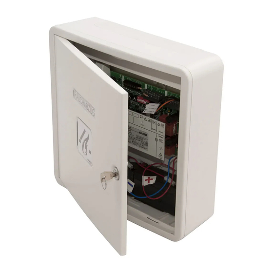
W x H x D = 250 x 250 x 91
Guarantee
You will get 2 years guarantee for all D+H products from date of verified handing over of the
system up to maximal 3 years after date of delivery, when mounting and starting has been
carried out by a D+H authorized distributor.
D+H guarantee is expired, with connection of D+H components with external systems or
with mixing of D+H products with parts of other manufacturers.
D+H Mechatronic AG • Georg-Sasse-Str. 28-32 • D-22949 Ammersbek • Tel. +4940-60565219 • Fax +4940-60565264
Smoke Vent System RZN 4402/04-K V2
authorized by the manufacturer.
Connection, mounting and functional testing by a
otherwise see "Informations for Starting".
RZN 4402-K V2
RZN 4404-K V2
installation
Approval-
Number:
G 501002
RZN 4402-KS V2
RZN 4404-KS V2
W x H x D = 400 x 300 x 120
Advertisement
Table of Contents

Related Manuals for D+H RZN 4402-K V2


Summary of Contents for D+H RZN 4402-K V2
-
Page 1: Guarantee
W x H x D = 400 x 300 x 120 Guarantee You will get 2 years guarantee for all D+H products from date of verified handing over of the system up to maximal 3 years after date of delivery, when mounting and starting has been carried out by a D+H authorized distributor. -
Page 2: Table Of Contents
Drives and smoke vent buttons ....8 D+H authorized expert companies have Wiring plan ..........9 been specially trained by D+H for carrying Connection cable ........10 out expertly this maintenance, and they get Connection ......... 11-17 automatically the latest maintenance Starting ............ -
Page 3: Introduction
Accumulator types, which are used for D+H Mechatronic AG smoke and heat vent systems must be VdS approved, and must be released by D+H Mechatronic AG to use in smoke and heat vent systems. According to DIN 18232 section 2 paragraph 10.2 the tests must be put down in an operational book, which the operator/ building owner must present to the building supervision authority on request. -
Page 4: System Overview
System Overview Drive group acoustical+ optical alarm devices* 230V / 50Hz signal Mains supply indicating board* signal contact* wind/rain control contact of transmitter* external system* smoke vent button smoke or ventilating thermal button* (min. 2 piece) detector* * optional function extension (separate components. -
Page 5: Mounting Of Housing 1
Mounting of housing 1 5/20 RZN 4402/04-K V2 Rev.:1.0... - Page 6 Mounting of housing 2 Piktograph explanation Mount control panel sheltered and easily Smoke and heat vent alarm accessible for maintenance in proximity of drive Control panel O.K. Fuse actuator Surface mounting: Mains existing 1. Remove cable cover 2. Fasten housing trough with 4 screws at Vent button function "ON"...
-
Page 7: View Motherboard Rzn 4402/04-K V2
View motherboard (RZN 4402/04-K V2) 7/20 RZN 4402/04-K V2 Rev.:1.0... -
Page 8: Drives And Smoke Vent Buttons
2 minutes for a duration of 30 minutes according to VdS 2581. For this, the drive must be blockage safe according to VdS 2580 par. 4.7. . All D+H drives meet this precondition. Otherwise Dip switch 10 is to be switched on OFF. -
Page 9: Wiring Plan
Mark fuses. Plug covering cap over mains binder on motherboard of control panel. Connecting cable: NYM-I 3x1.5 Connecting load: RZN 4402-K V2 = 60 VA RZN 4404-K V2=120 VA Weak Current Lines Install and feed separately from supply mains. Mark cable and terminal box red. -
Page 10: Connection Cable
Cable for D+H Smoke and Heat Vent Systems The smoke vent control panel is designed Detector Cables (Line): for opening smoke vent devices, which The detector cables are monitored for short operate by thermal ascending force and by circuit and for break. - Page 11 They are pinched in control panel for transport. Take it off there and connect according to plan. Terminal resistors must remain at binder RM 1,2, when no fire detector or external control exists. ** Fire detectors Only D+H system approved detectors must be used (see page 16). 11/20 RZN 4402/04-K V2 Rev.:1.0...
- Page 12 Parallel Connection of Smoke Vent Buttons - RT 42 Smoke-vent button Smoke-vent button 1st line 2nd line RT 42 RT 42 10kW 7x 0,8 5x 0,8 Shunt connection by customer 10kW RM / RT RZN 4402/ 04-K V2 12/20 RZN 4402/04-K V2 Rev.:1.0...
- Page 13 They are pinched in control panel for transport. Take it off there and connect according to plan. Terminal resistors must remain at binder RM 1,2, when no fire detector or external control exists. ** Fire detectors Only D+H system approved detectors must be used (see page 16). 13/20 RZN 4402/04-K V2 Rev.:1.0...
- Page 14 Connection of 2 Smoke Vent Buttons - RT 43-H/-N smoke vent button smoke vent button RT 43-H RT 43-N 10kW 10kW RM / RT RZN 4402/ 04-K V2 * shunt connection by customer 14/20 RZN 4402/04-K V2 Rev.:1.0...
-
Page 15: Connection
Parallel Connection of 2 x 2 Smoke Vent Buttons - RT43-H/-N Smoke vent button Smoke vent button 1st lane 2nd lane RT 43-H RT 43-H last smoke vent button each 10kW first to penultimate smoke vent button each Shunt connection by customer 10kW RM / RT... - Page 16 Connection of one fire detector line 180R single fire detector Connection of several fire detectors line 180R 180R 180R first fire detector second to penultimate ultimate fire detector fire detector The resistor must not be used, when line connections with 2-detector dependency are employed! Connection of magnetic clamps on RZN 4400-K V2 Magnetic...
- Page 17 Connection Examples control panel branch box branch box Zentrale Abzweigdose Abzweigdose Connection with line derivation: supply wires Mot a / Mot b derive off in par- allel, monitoring will be looped through all cables up to group end. weitere Abzweige connect in the branch box Abzweigdose...
-
Page 18: Starting
Informations for Starting Carry out following sight and performance checks for switching-on the smoke and heat vent control panel. Partial or incomplete connection of components can cause malfunction.. All cable Check following connections: mains 230V, drives, connected? smoke vent buttons, when necessary fire detectors and vent buttons. -
Page 19: Encode Of Line And Group
Encode of Line and Group Following functionings can be set with Dip switch (S1) on motherboard. Dip switch 1 on ON = OPEN-running time limitation. Using a potentiometer , running time in Open direction can be limited. If the vent button is actuated in Open direction, the drive will run open as long as the running time is set. -
Page 20: Examination
Automatic fire detectors: Release smoke detector individual by D+H- All sizes in millimetre • Rights to technical modifications reserved. • Reprinting and phototechnical 20/20 RZN 4402/04-K V2 Rev.:1.0 reproduction also in extracts has to be expressively authorized by D+H Mechatronic AG.
Need help?
Do you have a question about the RZN 4402-K V2 and is the answer not in the manual?
Questions and answers