
Related Manuals for IBASE Technology MBN806


Summary of Contents for IBASE Technology MBN806
- Page 1 MBN806 Networking Motherboards With AMD EPYC™ Embedded 3000 Series User’s Manual Version 1.0 (Nov. 2018)
- Page 2 No part of this publication may be reproduced, copied, stored in a retrieval system, translated into any language or transmitted in any form or by any means, electronic, mechanical, photocopying, or otherwise, without the prior written consent of IBASE Technology, Inc. (hereinafter referred to as “IBASE”).
-
Page 3: Compliance
0.1% by weight (1000 ppm) except for cadmium, limited to 0.01% by weight (100 ppm). • Lead (Pb) • Mercury (Hg) • Cadmium (Cd) • Hexavalent chromium (Cr6+) • Polybrominated biphenyls (PBB) • Polybrominated diphenyl ether (PBDE) MBN806 User Manual... -
Page 4: Important Safety Information
Do not disassemble, repair or make any modification to the device. Disassembly, modification, or any attempt at repair could generate hazards and cause damage to the device, even bodily injury or property damage, and will void any warranty. MBN806 User Manual... -
Page 5: Caution
Software in use (such as OS and application software, including the version numbers) 3. If repair service is required, you can download the RMA form at http://www.ibase.com.tw/english/Supports/RMAService/. Fill out the form and contact your distributor or sales representative. MBN806 User Manual... -
Page 6: Table Of Contents
BIOS Setup ................23 Introduction ................... 24 BIOS Setup ................... 24 Main Settings ..................25 Advanced Settings ................26 3.4.1 Trusted Computing ..............27 3.4.2 NCT5523D Super IO Configuration ........28 3.4.3 NCT7904D HW Monitor ............31 MBN806 User Manual... - Page 7 3.9.1 System Event Log ..............46 3.9.2 BMC Network Configuration ........... 47 Appendix ...................... 48 I/O Port Address Map ................49 Interrupt Request Lines (IRQ) ............... 52 Watchdog Timer Configuration .............. 53 Onboard Connector Types ..............58 MBN806 User Manual...
-
Page 8: Chapter 1 General Information
Chapter 1 General Information The information provided in this chapter includes: • Features • Packing List • Optional Accessories • Specifications • Overview • Dimensions... -
Page 9: Introduction
1.1 Introduction MBN806 is designed with the AMD EPYC™ Embedded 3201 processor and it can provide high performance and high integrity without a chipset. It is pecifically designed for the network security and management market. There are plenty of applications adopting network security or network management as listed below. -
Page 10: Features
• MBN806 1.4 Optional Accessories IBASE provide optional accessories as follows. Please contact us or your dealer if you need any. • Console Cable (160 cm, PK1-51) • IPMI Module (IDN100) • VGA Cable (40 cm, VGA21A) MBN806 User Manual... -
Page 11: Specifications
Operating: 0 ~ 60 °C (32 ~ 140 °F) Temperature • Storage: -20~ 80 °C (-4 ~ 176 °F) Relative 5 ~ 90% at 45 °C (non-condensing) Humidity All specifications are subject to change without prior notice. MBN806 User Manual... -
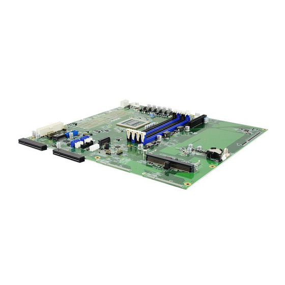
Page 12: Overview
General Information 1.6 Overview Top View Oblique View MBN806 User Manual... -
Page 13: Dimensions
1.7 Dimensions Unit: mm MBN806 User Manual... -
Page 14: Chapter 2 Hardware Configuration
Chapter 2 Hardware Configuration The information provided in this chapter includes: • Installation / Replacement • Information and locations of connectors... -
Page 15: Installation / Replacement
3. Gently push the module in an upright position until the ejector tabs of the memory slot close to hold the module in place when the module touches the bottom of the slot. To remove the module, press the ejector tabs outwards with your fingertips to eject the module. MBN806 User Manual... -
Page 16: Ipmi Module Installation / Replacement
To remove the module, press the clips outwards with your thumb and index finger of both hands. MBN806 User Manual... -
Page 17: Setting The Jumper
Open When two pins of a jumper are encased in a jumper cap, this jumper is closed, i.e. turned On. When a jumper cap is removed from two jumper pins, this jumper is open, i.e. turned Off. MBN806 User Manual... -
Page 18: Jumper & Connector Locations On Motherboard
Hardware Configuration 2.3 Jumper & Connector Locations on Motherboard Motherboard: MBN806 MBN806 User Manual... -
Page 19: Jumper Quick Reference
2.4 Jumper Quick Reference Function Connector Name Page AT & ATX Mode Clearing CMOS Data JBAT1 Factory Use Only JBMC1, JBMC2 2.4.1 AT & ATX Mode (JP3) Function Pin closed Illustration AT Mode (Default) ATX Mode MBN806 User Manual... - Page 20 Hardware Configuration 2.4.2 Clearing CMOS Data (JBAT1) Function Pin closed Illustration Normal (Default) Clearing CMOS MBN806 User Manual...
-
Page 21: Connectors Quick Reference
J3, J18 USB 3.0 Port IPMI Connector M.2 M2280 Slot DDR4 UDIMM/RDIMM/LRDIMM Slot J5, J6, J7, J8 SATA III Port CN1, CN4 Standard: PCIE1 PCIe (x8) Slot For IBN Card only: PCIE2, PCIE3 Factory Use Only J14, MBN806 User Manual... - Page 22 Hardware Configuration 2.5.1 External Power Switch Connector (J2) Signal Name Signal Name ATX_PSON#_EN 2.5.2 LPC Port (J19) Signal Name Signal Name LPC_LAD_0 LPC_RST_L LPC_LAD_1 LPC_LFRAME# LPC_LAD_2 VCC3_3 LPC_LAD_3 LPC24MB_BF_LAD MBN806 User Manual...
- Page 23 2.5.3 System Function Connector (JP5) Signal Name Signal Name ATXPWR_BTN# FRST_OUT VCC5 VCC3_3 -HDD_LED 2.5.4 Digital I/O Connector (JP6) Signal Name Signal Name VCC5 INT0_SIOGP22 INT0_SIOGP25 INT0_SIOGP23 INT0_SIOGP26 INT0_SIOGP24 INT0_SIOGP27 MBN806 User Manual...
- Page 24 Hardware Configuration 2.5.5 External SATA Power Connector (CN2, CN5) CN2: CN5: Signal Name Signal Name VCC5 VCC12 2.5.6 LCM Connector (CN3) (with RS-232 signal) Signal Name Signal Name LCM_RD1 LCM_TD1 VCC5 MBN806 User Manual...
- Page 25 2.5.7 Fan Connector (FAN1, FAN2, FAN3, FAN4, FAN5) FAN1: FAN2: FAN3: FAN5: FAN4: FAN1, FAN2, FAN3, FAN4: PWM fan connectors Signal Name Signal Name FAN_TACH VCC12 FAN_PWM FAN5: Normal fan connector Signal Name Signal Name FAN_TACH VCC12 MBN806 User Manual...
- Page 26 Hardware Configuration 2.5.8 Front I/O Connector (JP4) Signal Name Signal Name GPIO_BTN# RJ45-MDI8_P0 RJ45-MDI8_N0 VAUX33_LAN8 RJ45-MDI8_P1 RJ45-MDI8_N1 LAN8_LED2 RJ45-MDI8_P2 LAN8_LED0 RJ45-MDI8_N2 LAN8_LED1 RJ45-MDI8_P3 SATA_LED# RJ45-MDI8_N3 LED_SIOGP20 VCC5 LED_SIOGP21 MBN806 User Manual...
- Page 27 2.5.9 USB 2.0 Connector (F_USB1) Signal Name Signal Name HUB_FUSEVCC1 USB_PE_DP2_L USB_PE_DP1_L USB_PE_DM2_L USB_PE_DM1_L HUB_FUSEVCC1 2.5.10 Console Connector (COM1) Signal Name Signal Name 232_DCD1# 232_RD1 232_TD1 232_DTR1# 232_DSR1# 232_RTS1# 232_CTS1# 232_RI1# MBN806 User Manual...
- Page 28 2.5.11 ATX Power Connector (J3, J18) J18: Assignment Assignment Ground +12V Ground +12V Ground +12V Ground +12V J18: Assignment Assignment 3.3V 3.3V 3.3V -12V Ground Ground PS-ON Ground Ground Ground Ground Ground Power good 5VSB +12V +12V +3.3V Ground MBN806 User Manual...
- Page 29 2.5.12 USB 3.0 Connector (J17) Signal Name Signal Name USB3.0_VCC_B USB20_L_P4 USB3_CRX_R_DTX_N3 USB20_L_N4 USB3_CRX_R_DTX_P3 Ground Ground USB3_CTX_R_DRX_P4 USB3_CTX_R_DRX_N3 USB3_CTX_R_DRX_N4 USB3_CTX_R_DRX_P3 Ground Ground USB3_CRX_R_DTX_P4 USB20_L_N3 USB3_CRX_R_DTX_N4 USB20_L_P3 USB3.0_VCC_B MBN806 User Manual...
-
Page 30: Chapter 3 Bios Setup
Chapter 3 BIOS Setup This chapter describes the different settings available in the AMI BIOS that comes with the board. The topics covered in this chapter are as follows: • Main Settings • Advanced Settings • Chipset Settings • Security Settings •... -
Page 31: Introduction
These defaults have been carefully chosen by both AMI and your system manufacturer to provide the absolute maximum performance and reliability. Changing the defaults could make the system unstable and crash in some cases. MBN806 User Manual... -
Page 32: Main Settings
BIOS Setup 3.3 Main Settings BIOS Setting Description System Date Sets the date. Use the <Tab> key to switch between the data elements. System Time Set the time. Use the <Tab> key to switch between the data elements. MBN806 User Manual... -
Page 33: Advanced Settings
3.4 Advanced Settings This section allows you to configure, improve your system and allows you to set up some system features according to your preference. MBN806 User Manual... -
Page 34: Trusted Computing
BIOS Setup 3.4.1 Trusted Computing BIOS Setting Description Security Device Support Enables / Disables BIOS support for security device. The operating system will not show the security device. TCG EFI protocol and INT1A interface will not be available. MBN806 User Manual... -
Page 35: Nct5523D Super Io Configuration
You can enable / disable the serial port and select an optimal settings for the Super IO device. Restore AC Power Loss Select AC power state when power is re- applied after a power failure. Options: Power Off, Power On, Last State MBN806 User Manual... - Page 36 BIOS Setup 3.4.2.1. Serial Port 1 Configuration BIOS Setting Description Serial Port Sets parameters of Serial Ports (COM). Change Settings Selects an optimal settings for Super I/O device. MBN806 User Manual...
- Page 37 3.4.2.2. Serial Port 2 Configuration BIOS Setting Description Serial Port Sets parameters of Serial Ports (COM). Change Settings Selects an optimal settings for Super I/O device. MBN806 User Manual...
-
Page 38: Nct7904D Hw Monitor
°C, 95°C Temperatures / Voltages These fields are the parameters of the / Fan Speed hardware monitoring function feature of the motherboard. The values are read-only as monitored by the system and showing the PC health status MBN806 User Manual... -
Page 39: Serial Port Console Configuration
Enables / Disables Console Redirection. Console Redirection The settings specify how the host computer Settings and the remote computer (which the user is using) will exchange data. Both computers should have the same or compatible settings. Sets parameters of Console Redirection. MBN806 User Manual... - Page 40 0 if the num of 1’s in the data bits is even. Options: None, Even, Odd, Mark, Space Stop Bits Stop bits indicate the end of a serial data packet. (A start bit indicates the beginning). The standard setting is 1 stop bit. Options: 1, 2 MBN806 User Manual...
- Page 41 With this mode enabled, only text will be sent. This is to capture terminal data. Resolution 100x31 Enables / Disables extended terminal resolution. Putty Key pad Select FunctionKey and keyPad on Putty. Options: VT100, LINUX, XTERMR6, SC0, ESCN, VT400 MBN806 User Manual...
-
Page 42: Cpu Configuration
BIOS Setup 3.4.5 CPU Configuration BIOS Setting Description Node 0 Information View memory information related to node 0. 3.4.6 NVMe Configuration MBN806 User Manual... -
Page 43: Usb Configuration
Sets the time-out value 1, 5, 10 or 20 sec(s) for Control, Bulk, and Interrupt transfers. Device reset time-out Sets the seconds (10, 20, 30, 40 secs) of delaying execution of start unit command to USB mass storage device. MBN806 User Manual... -
Page 44: Pcie Slot Configuration
BIOS Setup 3.4.8 PCIE Slot Configuration BIOS Setting Description PCIE Slot A / B Configures the PCIe slot as x8 or x4/x4 MBN806 User Manual... -
Page 45: Lan Bypass Configuration
Bypass mode during power-off or WDT initiates bypass. System will not reboot. • Firewall Mode: All LAN ports in bypass until OS has control ability to change LAN ports in normal. • Custom Mode: All LAN ports can be configured independently. MBN806 User Manual... -
Page 46: Security Settings
BIOS Setup 3.5 Security Settings BIOS Setting Description Administrator Password Sets an administrator password for the setup utility. User Password Sets a user password. MBN806 User Manual... -
Page 47: Boot Settings
This option controls Legacy/UEFI ROMs priority. Options: UEFI and Legacy, Legacy only, UEFI only Network PXE OpROM Controls the execution of UEFI and Legacy PXE OpROM. Options: Do not launch, UEFI, Legacy Boot Option Priorities Sets the system boot order. MBN806 User Manual... -
Page 48: Save & Exit Settings
Exits system setup after saving the changes. Save Changes and Reset Resets the system after saving the changes. Discard Changes and Resets system setup without saving any Reset changes. Restore Defaults Restores / Loads defaults values for all the setup options. MBN806 User Manual... -
Page 49: Event Logs
Event Logs BIOS Setting Description Change SMBIOS Event Press Enter to change the SMBIOS event log Log Settings configuration. View SMBIOS Event Log MBN806 User Manual... -
Page 50: Change Smbios Event Log Settings
METW Mutiple event time window: The number of minutes which must pass between duplicate log entries which utilize a multiple-event counter. The value ranges from 0 to 99 minutes. MBN806 User Manual... -
Page 51: View Smbios Event Log Settings
OEM codes (if not already converted to legacy). Convert OEM Codes Enables / Disables the converting of EFI status codes to standard SMBIOS types (not all may be translated.). 3.8.2 View SMBIOS Event Log Settings MBN806 User Manual... -
Page 52: Server Management
Disable: keep original IRQ, IObase and active UART1 System Event Log Allows you to configure the settings for system event log. BMC self test log Allows you to configure when to erase the log. BMC Network Configures BMC network parameters. Configuration MBN806 User Manual... -
Page 53: System Event Log
Allows you to choose options for reactions to a full SEL. Options: Do nothing, Erase immediately Log EFI Status Codes Disables the logging of EFI status codes or log only error code or only progress code or both. Options: Disabled, Both, Error code, Progress code MBN806 User Manual... -
Page 54: Bmc Network Configuration
BIOS Setup 3.9.2 BMC Network Configuration BIOS Setting Description Configureation Address Configures LAN channel parameters statically or Souce dynamically (by BIOS or BMC). Options: Unspecified, Static, DynamicBmcDhcp, DynamicBmcNonDhcp MBN806 User Manual... -
Page 55: Appendix
Appendix This section provides the mapping addresses of peripheral devices and the sample code of watchdog timer configuration. • I/O Port Address Map • Interrupt Request Lines (IRQ) • Watchdog Timer Configuration... -
Page 56: I/O Port Address Map
PCI Express to PCI/PCI-X Bridge 0x000003B0-0x000003DF Microsoft Basic Display Adapter 0x000003B0-0x000003DF PCI Express Root Port 0x0000B000-0x0000BFFF PCI Express to PCI/PCI-X Bridge 0x0000B000-0x0000BFFF Microsoft Basic Display Adapter 0x0000B000-0x0000BFFF PCI Express Root Port 0x000003C0-0x000003DF PCI Express to PCI/PCI-X Bridge MBN806 User Manual... - Page 57 Motherboard resources 0x0000040B-0x0000040B Motherboard resources 0x000004D6-0x000004D6 Motherboard resources 0x00000C00-0x00000C01 Motherboard resources 0x00000C14-0x00000C14 Motherboard resources 0x00000C50-0x00000C51 Motherboard resources 0x00000C52-0x00000C52 Motherboard resources 0x00000C6C-0x00000C6C Motherboard resources 0x00000C6F-0x00000C6F Motherboard resources 0x00000CD0-0x00000CD1 Motherboard resources 0x00000CD2-0x00000CD3 Motherboard resources 0x00000CD4-0x00000CD5 Motherboard resources 0x00000CD6-0x00000CD7 Motherboard resources MBN806 User Manual...
- Page 58 0x00000900-0x0000090F Motherboard resources 0x00000910-0x0000091F Motherboard resources 0x0000FE00-0x0000FEFE Motherboard resources 0x00000061-0x00000061 System speaker 0x00000081-0x00000083 Direct memory access controller 0x00000087-0x00000087 Direct memory access controller 0x00000089-0x0000008B Direct memory access controller 0x0000008F-0x0000008F Direct memory access controller 0x000000C0-0x000000DF Direct memory access controller MBN806 User Manual...
-
Page 59: Interrupt Request Lines (Irq)
AMD USB 3.0 eXtensible Host Controller - 1.0 (Microsoft) IRQ 4294967278 AMD USB 3.0 eXtensible Host Controller - 1.0 (Microsoft) IRQ 4294967277 AMD USB 3.0 eXtensible Host Controller - 1.0 (Microsoft) IRQ 4294967276 AMD USB 3.0 eXtensible Host Controller - 1.0 (Microsoft) MBN806 User Manual... -
Page 60: Watchdog Timer Configuration
(NCT5523D_BASE) #define NCT5523D_DATA_PORT (NCT5523D_BASE+1) //--------------------------------------------------------------------------- #define NCT5523D_REG_LD 0x07 //--------------------------------------------------------------------------- #define NCT5523D_UNLOCK 0x87 #define NCT5523D_LOCK 0xAA //--------------------------------------------------------------------------- unsigned int Init_NCT5523D(void); void Set_NCT5523D_LD( unsigned char); void Set_NCT5523D_Reg( unsigned char, unsigned char); unsigned char Get_NCT5523D_Reg( unsigned char); //--------------------------------------------------------------------------- #endif //__NCT5523D_H MBN806 User Manual... - Page 61 (SIO == 0) printf("Can not detect Nuvoton NCT5523D, program abort.\n"); return(1); WDTInitial(); WDTEnable(10); WDTDisable(); return 0; //--------------------------------------------------------------------------- void WDTInitial(void) unsigned char bBuf; Set_NCT5523D_LD(0x08); //switch to logic device 8 bBuf = Get_NCT5523D_Reg(0x30); bBuf &= (~0x01); Set_NCT5523D_Reg(0x30, bBuf); //Enable WDTO //--------------------------------------------------------------------------- MBN806 User Manual...
- Page 62 //enable timer bBuf = Get_NCT5523D_Reg(0xF0); bBuf &= (~0x08); Set_NCT5523D_Reg(0xF0, bBuf); //count mode is second Set_NCT5523D_Reg(0xF1, NewInterval); //set timer //--------------------------------------------------------------------------- void WDTDisable(void) Set_NCT5523D_LD(0x08); //switch to logic device 8 Set_NCT5523D_Reg(0xF1, 0x00); //clear watchdog timer Set_NCT5523D_Reg(0x30, 0x00); //watchdog disabled //--------------------------------------------------------------------------- MBN806 User Manual...
- Page 63 Init_Finish; } NCT5523D_BASE = 0x2E; result = NCT5523D_BASE; ucDid = Get_NCT5523D_Reg(0x20); if (ucDid == 0xC4) //NCT5523D?? goto Init_Finish; } NCT5523D_BASE = 0x00; result = NCT5523D_BASE; Init_Finish: return (result); //--------------------------------------------------------------------------- void Unlock_NCT5523D (void) outportb(NCT5523D_INDEX_PORT, NCT5523D_UNLOCK); outportb(NCT5523D_INDEX_PORT, NCT5523D_UNLOCK); //--------------------------------------------------------------------------- MBN806 User Manual...
- Page 64 LD); Lock_NCT5523D(); //--------------------------------------------------------------------------- void Set_NCT5523D_Reg( unsigned char REG, unsigned char DATA) Unlock_NCT5523D(); outportb(NCT5523D_INDEX_PORT, REG); outportb(NCT5523D_DATA_PORT, DATA); Lock_NCT5523D(); //--------------------------------------------------------------------------- unsigned char Get_NCT5523D_Reg(unsigned char REG) unsigned char Result; Unlock_NCT5523D(); outportb(NCT5523D_INDEX_PORT, REG); Result = inportb(NCT5523D_DATA_PORT); Lock_NCT5523D(); return Result; //----------------------------------------------------------------------- MBN806 User Manual...
-
Page 65: Onboard Connector Types
Front I/O 0126-01-203-200 20P 2.54 mm-pitch Connector (female) UISB 2.0 F_USB1 Connector DF11-8DP-2DSA DF11-8DS-2C Console COM1 Connector DF11-10DP-2DSA DF11-10DS-2C ATX Power Molex Molex J3, J18 Connector 39-28-8080 39-01-2080 PINREX Dupont USB 3.0 Port 52X-40-20GU52 20P 2 mm-pitch (female) MBN806 User Manual...
Need help?
Do you have a question about the MBN806 and is the answer not in the manual?
Questions and answers