
Related Manuals for IBASE Technology MB997


Summary of Contents for IBASE Technology MB997
- Page 1 MB997 ® ® Intel 9th Gen. Xeon -E / Core™ DT Processor Based ATX Motherboard User’s Manual Version 1.0 (November 2020)
- Page 2 No part of this publication may be reproduced, copied, stored in a retrieval system, translated into any language or transmitted in any form or by any means, electronic, mechanical, photocopying, or otherwise, without the prior written consent of IBASE Technology, Inc. (hereinafter referred to as “IBASE”). Disclaimer IBASE reserves the right to make changes and improvements to the products described in this document without prior notice.
- Page 3 0.1% by weight (1000 ppm) except for cadmium, limited to 0.01% by weight (100 ppm). • Lead (Pb) • Mercury (Hg) • Cadmium (Cd) • Hexavalent chromium (Cr6+) • Polybrominated biphenyls (PBB) • Polybrominated diphenyl ether (PBDE) MB997 User’s Manual...
- Page 4 CAUTION Replace only with the same or equivalent type recommended by the manufacturer. Dispose of used batteries according to the manufacturer’s instructions or recycle them at a local recycling facility or battery collection point. MB997 User’s Manual...
- Page 5 Software in use (such as OS and application software, including the version numbers) If repair service is required, you can download the RMA form at http://www.ibase.com.tw/english/Supports/RMAService/. Fill out the form and contact your distributor or sales representative. MB997 User’s Manual...
-
Page 6: Table Of Contents
Hardware Configuration ........11 Installations ..................12 2.1.1 Installing the Memory ............12 Setting the Jumpers ................13 Jumper & Connector Locations on MB997 ......... 14 Jumpers Quick Reference ..............15 2.4.1 Clear CMOS Data (JP7) ............15 2.4.2 Clear RTC (JP6) ..............16 2.4.3... - Page 7 Network Stack Configuration ..........58 Chipset Settings .................60 Security Settings ................63 Boot Settings ..................65 Save & Exit Settings ................66 Appendix ..................67 I/O Port Address Map ................68 Interrupt Request Lines (IRQ) ............70 Watchdog Timer Configuration ............71 On-Board Connector Types ...............76 MB997 User’s Manual...
- Page 8 This page is intentionally left blank. MB997 User’s Manual viii...
-
Page 9: Chapter 1 General Information
Chapter 1 General Information The information provided in this chapter includes: • Features • Packing List • Specifications • Block Diagram • Product View • Board Dimensions... -
Page 10: Introduction
Introduction MB997 is an ATX motherboard that supports Intel® Xeon® E/ Core™ i7/i5/i3 processors and four DDR4 DIMM memory sockets with a capacity of up to 128GB. The board features high-performance graphics processing to create media-rich content and brilliant HD entertainment with DVI-D, HDMI (2.0a) and DisplayPort display interface. -
Page 11: Packing List
General Information Packing List Your MB997 package should include the items listed below. If any of the items below is missing, contact the distributor or dealer from whom you purchased the product. • MB997 Motherboard • I/O shield • SATA cable (SATA-3F) •... -
Page 12: Specifications
+ Realtek audio codec ALC662-VD0-GR w/ 5.1 channels Power Supply ATX Power, 12V H/W Monitor Watchdog Yes (256 segments, 0, 1, 2…255 sec / min) Timer BIOS AMI BIOS RAID RAID 0/1/5/10 iSMART iAMT 11.6 ECC will be supported per CPU SKUs. MB997 User’s Manual... - Page 13 Operating: 0 ~ 60 °C (32 ~ 140 °F) • Temperature Storage: -20 ~ 80 °C (-4 ~ 176 °F) • Relative 0 ~ 90 %, non-condensing at 60 °C Humidity All specifications are subject to change without prior notice. MB997 User’s Manual...
-
Page 14: Block Diagram
Block Diagram MB997 User’s Manual... -
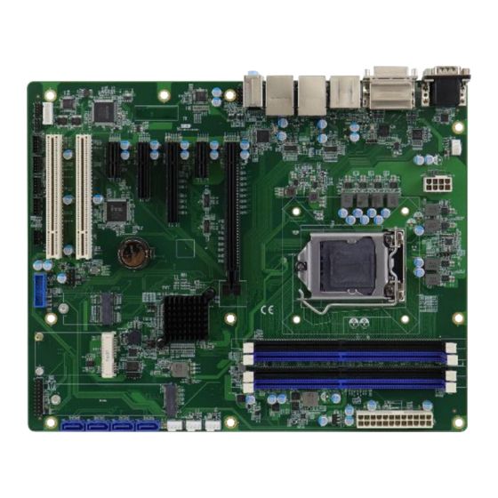
Page 15: Product View
Top View I/O View Name Name COM1 Port (CN1) USB 3.1 Ports COM2 Port (CN1) GbE LAN Ports (CN3, CN4) DVI-D Port (CN11) Line-In (top) (CN5) HDMI Port (CN12) Audio Line-Out (middle) (CN5) DisplayPort (CN2) Microphone-In (bottom) (CN5) MB997 User’s Manual... - Page 16 Bottom View *The photos above are for reference only. Some minor components may differ. MB997 User’s Manual...
-
Page 17: Dimensions
General Information Dimensions MB997 User’s Manual... - Page 18 This page is intentionally left blank. MB997 User’s Manual...
-
Page 19: Chapter 2 Hardware Configuration
Chapter 2 Hardware Configuration This section provides information on jumper settings and connectors on the board in order to set up a workable system. The topics covered are: • Essential installations before you begin: CPU and the memory • Jumper and connector locations •... -
Page 20: Installations
Gently push the module in an upright position until the ejector tabs of the memory slot close to hold the module in place when the module touches the bottom of the slot. To remove the module, press the ejector tabs outwards with your fintertips to eject the module. MB997 User’s Manual... -
Page 21: Setting The Jumpers
Open When two pins of a jumper are encased in a jumper cap, this jumper is closed, i.e. turned On. When a jumper cap is removed from two jumper pins, this jumper is open, i.e. turned Off. MB997 User’s Manual... -
Page 22: Jumper & Connector Locations On Mb997
Jumper & Connector Locations on MB997 MB997 User’s Manual... -
Page 23: Jumpers Quick Reference
Hardware Configuration Jumpers Quick Reference Jumper Function Page Name Clear CMOS Data 錯誤! 尚未定義書 Clear RTC 籤。 Flash Descriptor Security Override 2.4.1 Clear CMOS Data (JP7) Function Pin closed Illustration Normal (default) Clear CMOS MB997 User’s Manual... -
Page 24: Clear Rtc (Jp6)
2.4.2 Clear RTC (JP6) Function Pin closed Illustration Normal (default) Clear CMOS MB997 User’s Manual... -
Page 25: Flash Descriptor Security Override (Jp5)
Hardware Configuration 2.4.3 Flash Descriptor Security Override (JP5) Function JP5 Pin Illustration Disabled (default) Open Enabled Close *Factory use only. MB997 User’s Manual... -
Page 26: Connectors Quick Reference
CN12 COM3, COM4, COM5, COM6 RS232 J9, J8, J6, J5 Serial Ports CPU Fan Power Connector CPU_FAN1 PS2 Keyboard/Mouse USB2 Connector USB3 Connector Front Panel Connector 24-pin ATX Power Connector SYS_FAN1, SYS_FAN2, System Fan Power Connectors SYS_FAN3 MB997 User’s Manual... -
Page 27: Cn1: Com1 & Com2 Ports
DCD, Data carrier detect DSR, Data set ready RXD, Receive data RTS, Request to send TXD, Transmit data CTS, Clear to send DTR, Data terminal ready RI, Ring indicator Ground Signal Name RS-232 RS-422 RS-485 DATA- DATA+ Ground Ground Ground MB997 User’s Manual... -
Page 28: J3: Digital I/O Connector
2.5.2 J3: Digital I/O Connector Signal Name Signal Name Ground OUT3 OUT1 OUT2 OUT0 MB997 User’s Manual... -
Page 29: Atx_12V_2X1: Atx 12V Power Connector
Hardware Configuration 2.5.3 ATX_12V_2X1: ATX 12V Power Connector Signal Name Signal Name Ground +12V Ground +12V Ground +12V Ground +12V MB997 User’s Manual... -
Page 30: Cn7: Sata3 #2 Connector
2.5.4 CN7: SATA3 #2 Connector Signal Name Signal Name Ground Ground Ground MB997 User’s Manual... -
Page 31: Cn8: Sata3 #0 Connector
Hardware Configuration 2.5.5 CN8: SATA3 #0 Connector Signal Name Signal Name Ground Ground Ground MB997 User’s Manual... -
Page 32: Cn9: Sata3 #3 Connector
2.5.6 CN9: SATA3 #3 Connector Signal Name Signal Name Ground Ground Ground MB997 User’s Manual... -
Page 33: Cn10: Sata3 #1 Connector
Hardware Configuration 2.5.7 CN10: SATA3 #1 Connector Signal Name Signal Name Ground Ground Ground MB997 User’s Manual... -
Page 34: Cn12: Hdmi Connector
CN12: HDMI Connector Signal Name Signal Name TMDS Data2+ TMDS Clock Shield TMDS Data2 Shield TMDS Clock- TMDS Data2- TMDS Data1+ Reserved TMDS Data1 Shield TMDS Data1- TMDS Data0+ TMDS Data0 Shield TMDA Data0- Hot Plug TMDS Clock+ MB997 User’s Manual... -
Page 35: J9, J8, J6, J5: Com3, Com4, Com5, Com6 Rs232
Hardware Configuration 2.5.9 J9, J8, J6, J5: COM3, COM4, COM5, COM6 RS232 Serial Ports (HK_DF11-10S-PA66H) Signal Name Signal Name DCD# SIN# SOUT RTS# DSR# DTR# CTS# MB997 User’s Manual... -
Page 36: Cpu_Fan1: Cpu Fan Power Connector (Pwm Only)
2.5.10 CPU_FAN1: CPU Fan Power Connector (PWM Only) Signal Name Signal Name Ground Rotation detection +12V Control MB997 User’s Manual... -
Page 37: J10:Ps2 Keyboard/Mouse
Hardware Configuration 2.5.11 J10:PS2 Keyboard/Mouse (HK_DF11-8S-PA66H) Signal Name Signal Name KBDA KBCL# MB997 User’s Manual... -
Page 38: J13: Usb2 Connector
2.5.12 J13: USB2 Connector (E-CALL_0126-01-2811009) Signal Name Signal Name Ground MB997 User’s Manual... -
Page 39: J14: Usb3 Connector
Hardware Configuration 2.5.13 J14: USB3 Connector (PINREX_52X-40-20GU52) Signal Name Signal Name P1_SSRX- P1_SSRX+ P2_SSRX- P2_SSRX+ P1_SSTX- P1_SSTX+ P2_SSTX- P2_SSTX+ P1_U2_D- P1_U2_D+ P2_U2_D P2_U2_D+ MB997 User’s Manual... -
Page 40: J23: Front Panel Connector
2.5.14 J23: Front Panel Connector Signal Name Signal Name Power LED+ Power LED- SPK(VCC) Power BTN Power BTN Reset BTN Reset BTN HDD LED+ HDD LED- MB997 User’s Manual... -
Page 41: J25: 24-Pin Atx Power Connector
Hardware Configuration 2.5.15 J25: 24-pin ATX power connector Signal Name Signal Name 3.3V 3.3V -12V 3.3V Ground Ground PS-ON Ground Ground Ground Ground Ground Power good 5VSB +12V +12V Ground 3.3V MB997 User’s Manual... -
Page 42: Sys_Fan1, Sys_Fan2, Sys_Fan3: System Fan Power Connector (Pwm Only)
2.5.16 SYS_FAN1, SYS_FAN2, SYS_FAN3: System Fan Power Connector (PWM Only) Signal Name Signal Name Ground Rotation detection +12V Control MB997 User’s Manual... -
Page 43: Chapter 3 Drivers Installation
Chapter 3 Drivers Installation This chapter introduces installation of the following drivers: • ® Intel Chipset Software Installation Utility • HD Graphics Driver • HD Audio Driver • LAN Driver • ® Intel Management Engine Drivers Installation... -
Page 44: Introduction
INF files for Plug & Play function for Intel chipset components. Follow the instructions below to complete the installation. Insert the disk enclosed in the package with the board. Click Intel on the left pane and then Intel(R) Coffeelake Chipset Drivers on the right pane. MB997 User’s Manual... - Page 45 Next to continue. Accept the software license agreement and proceed with the installation process. On the Readme File Information screen, click Install for installation. The driver has been completely installed. Restart the computer for changes to take effect. MB997 User’s Manual...
-
Page 46: Hd Graphics Driver Installation
When the Welcome screen appears, click Next to continue. Accept the license agreement and click Next. On the Readme File Information screen, click Next until the installation starts. After Setup is Complete, restart the computer for changes to take effect. MB997 User’s Manual... -
Page 47: Hd Audio Driver Installation
Click Realtek High Definition Audio Driver. When the Welcome screen appears, click Next. Realtek High Definition Audio Driver will then configure the new software installation. When the InstallShield Wizard has completed the installation, restart the computer for changes to take effect. MB997 User’s Manual... -
Page 48: Lan Driver Installation
On the next screen,accept the license agreement and click Next. When the Setup Options screen appears, select the program features you want installed and click Next. When the Ready to Install the Program screen appears, click Install. When the Install wizard Completed screen appears, click Finish. MB997 User’s Manual... -
Page 49: Intel ® Management Engine Drivers Installation
On the Welcome screen, click Next. Accept the license agreement and click Next. On the Destination Folder screen, click Next. The Install Wizard is now ready to begin installation. Click Install. When Setup has completed the installation,click Finish. MB997 User’s Manual... -
Page 50: Chapter 4 Bios Setup
Chapter 4 BIOS Setup This chapter describes the different settings available in the AMI BIOS that comes with the board. The topics covered in this chapter are as follows: • Main Settings • Advanced Settings • Chipset Settings • Boot Settings •... -
Page 51: Introduction
These defaults have been carefully chosen by both AMI and your system manufacturer to provide the absolute maximum performance and reliability. Changing the defaults could make the system unstable and crash in some cases. MB997 User’s Manual... -
Page 52: 4.3 Main Settings
Default Ranges: Year: 2005-2099 Months: 1-12 Days: dependent on month System Time Set the time. Use Tab to switch between the Time elements. REMARKS: The descriptions are based on the BIOS screens from MB997AF and MB997AF-C246 motherboard models. MB997 User’s Manual... -
Page 53: 4.4 Advanced Settings
Enables / Disables option ROM execution CSM Configuration settings, etc. NVMe Configuration NVMe Device Options Settings Network Stack Network Stack Settings Configuration * These two configurations are available on MB997AF and MB997AF-C246 motherboard models, but not on MB997EF. MB997 User’s Manual... -
Page 54: Cpu Configuration
Technology Vanderpool Technology. Number of cores to enable in each processor Active Processor package. Cores Options: All, 1, 2, 3, 4, 5 Hyper-Threading Options: Enabled, Disabled. Intel Trusted Execution Options: Enabled, Disabled. Technology MB997 User’s Manual... -
Page 55: Pch-Fw Configuration
BIOS Setup 4.4.2 PCH-FW Configuration PCH-FW Configuration configures the management engine technology parameters. REMARKS: PCH-FW Configuration is available on MB997AF and MB997AF-C246 motherboard models, but not on MB997EF. MB997 User’s Manual... -
Page 56: Amt Configuration
4.4.3 AMT Configuration AMT Configuration configures Intel(R) Active Management Technology Parameters. BIOS Setting Description ASF Support Enable/Disable Alert Standard Format support. REMARKS: AMT Configuration is available on MB997AF and MB997AF-C246 motherboard models, but not on MB997EF. MB997 User’s Manual... -
Page 57: Trusted Computing
TPM 1.2 will restrict support to TPM 1.2 devices. Device Select TPM 2.0 will restrict to support TPM 2.0 devices. Auto will support both, with the default set to TPM 2.0 devices. If not found, TPM 1.2 devices will be enumerated. MB997 User’s Manual... -
Page 58: Acpi Settings
(OS/S4 Sleep State). This option may be not effective with some OS. ACPI Sleep State Selects an ACPI sleep state where the system will enter when the Suspend button is pressed. Options: Suspend Disabled, S3 (Suspend to RAM) MB997 User’s Manual... -
Page 59: Nct66860 Super Io Configuration
。IO=2F8h; IRQ=3,4, 5, 6, 7,8, 9, 10, 11, 12; 。IO=3E8h; IRQ=3,4, 5, 6, 7,8, 9, 10, 11, 12; 。IO=2E8h; IRQ=3,4, 5, 6, 7,8, 9, 10, 11, 12; Device Mode Change the Serial Port mode. Options: RS232, RS422,RS485 MB997 User’s Manual... -
Page 60: Hardware Monitor
The values are read-only values as monitored by the system and show the PC health status. CPU Shutdown Options: Disabled / 70 °C / 75 °C / 80 °C / 85 °C / Temperature 90 °C / 95 °C MB997 User’s Manual... -
Page 61: Ismart Controller 4.0 (Esio)
Enables / Disables the system to be turned on Power Failure automatically after a power failure. Shutdown Resume Options: Disable, Enable Temperature Guardian Options: Disable, Enable * Standby Power on S5(ERP) is available on MB997EF only and not on the MB997AF and MB997AF-C246 motherboard models. MB997 User’s Manual... -
Page 62: F8126Sec Super Io Configuration
4.4.9 F8126SEC Super IO Configuration BIOS Setting Description Serial Port (1, 2, 3, 4) Enables / Disables the serial port. Select an optimal settings for Super IO Device. Change Settings MB997 User’s Manual... -
Page 63: Usb Configuration
100ms. But for a Hub port, the delay is taken from Hub descriptor. Options: Auto / Manual Mass storage device emulation type. ‘Auto’ Mass Storage enumerates devices according to their media Devices format. Optical deives are emulated as MB997 User’s Manual... - Page 64 ‘CDROM’. Drives with no media will be emulated according to a drive type. MB997 User’s Manual...
-
Page 65: Csm Configuration
Postponed – execute the trap during legacy boot. HDD Connection Some OS require HDD handles to be adjusted, Order i.e. OS isinstalled ondrive 80h. Network Controls the execution of UEFI and Legacy PXE OpROM. Options: Do not launch / Legacy MB997 User’s Manual... -
Page 66: Nvme Configuration
Support to Enable/Disable IPSEC certificate for IPSEC Certificate Ikev. Wait time in seconds to press ESC key to abort PXE boot wait the PXE boot. Use either +/- or numeric keys to time set the value. MB997 User’s Manual... - Page 67 BIOS Setup Number of times the presence of media will be Media detect checked. Use either =/- or numeric keys to set the count value. MB997 User’s Manual...
-
Page 68: 4.5 Chipset Settings
BIOS Setting Description System Agent (SA) System Agent (SA) parameters Configuration PCH-IO PCH parameters Configuration 4.5.1 System Agent (SA) Configuration BIOS Setting Description Graphics Configures the graphics settings. Configuration VT-d Checks if VT-d function on MCH is supported. MB997 User’s Manual... - Page 69 Sets the aperture size as 128 MB / 256 MB / 512 MB / 1024 MB / 2048 MB. Note: Above 4 GB MMIO BIOS assignment is automatically enabled when selecting 2048 MB aperture. To use this feature, disable CSM support. MB997 User’s Manual...
- Page 70 Enable or disable PS_ON ( ) support a new C10 state from the CPU on PS_ON Enable desktop SKUs that enables a lower power target that will be required by the California Energy Commission (CEC). MB997 User’s Manual...
-
Page 71: 4.6 Security Settings
Install factory default Secure Boot keys after the Provision platform reset and while the System is in Setup mode Enroll Efi Image Allow the image to run in Secure Boot mode. Enroll SHA256 Hash certificate of a PE image into Authorized Signature Database (db) MB997 User’s Manual... - Page 72 MB997 User’s Manual...
-
Page 73: 4.7 Boot Settings
65535(0xFFFF) means indefinite waiting. Bootup NumLock Selects the keyboard NumLock state. State Quiet Boot Enables / Disables Quiet Boot option. Boot mode select Selects boot mode: Legacy / UEFI. Boot Option Priorities Sets the system boot order. MB997 User’s Manual... -
Page 74: 4.8 Save & Exit Settings
Restores / Loads defaults values for all the Restore Defaults setup options. Save as User Saves the changes done so far as User Defaults Defaults. Restore User Restores the user defaults to all the setup Defaults options. MB997 User’s Manual... -
Page 75: Appendix
Appendix This section provides the mapping addresses of peripheral devices, the sample code of watchdog timer configuration, and types of on-board connectors. -
Page 76: I/O Port Address Map
Programmable interrupt controller 0x00000030-0x00000031 Programmable interrupt controller 0x00000034-0x00000035 Programmable interrupt controller 0x00000038-0x00000039 Programmable interrupt controller 0x0000003C-0x0000003D Programmable interrupt controller 0x000000A0-0x000000A1 Programmable interrupt controller 0x000000A4-0x000000A5 Programmable interrupt controller 0x000000A8-0x000000A9 Programmable interrupt controller 0x000000AC-0x000000AD Programmable interrupt controller 0x000000B0-0x000000B1 Programmable interrupt controller MB997 User’s Manual... - Page 77 0x00004080-0x00004083 Standard SATA AHCI Controller 0x00004060-0x0000407F Standard SATA AHCI Controller 0x00000040-0x00000043 System timer 0x00000050-0x00000053 System timer 0x00002000-0x000020FE Motherboard resources 0x00004000-0x0000403F Intel(R) UHD Graphics 630 0x00000060-0x00000060 Standard PS/2 Keyboard 0x00000064-0x00000064 Standard PS/2 Keyboard 0x0000EFA0-0x0000EFBF Intel(R) SMBus - A323 MB997 User’s Manual...
-
Page 78: Interrupt Request Lines (Irq)
Intel(R) PCI Express Root Port #5 - A33C IRQ 4294967294 Intel(R) PCIe Controller (x16) - 1901 IRQ 4294967289 Intel(R) UHD Graphics 630 Intel(R) USB 3.1 eXtensible Host Controller IRQ 4294967288 - 1.10 (Microsoft) IRQ 4294967291 Standard SATA AHCI Controller MB997 User’s Manual... -
Page 79: Watchdog Timer Configuration
**endptr; char SIO; printf("Nuvoton NCT6686D watch dog program\n"); SIO = Init_NCT6686D(); if (SIO == 0) printf("Can not detect NCT6686D, program abort.\n"); return(1); }//if (SIO == 0) if (argc != 2) MB997 User’s Manual... - Page 80 OutPage, OutIndex, OutValue; NCT6686EnterPageConfig(); OutPage = 0x02; //Page2 OutIndex = 0x40; //Index 0x40 WDT Timer Configuration OutValue = 0x00; //Bit1:Select 0:Second Mode 1:Minute Mode //Bit0:WDT_En 1:Enable 0:Disable NCT6686SetPageValue(OutPage, OutIndex, OutValue); NCT6686ExitConfig(); Delay_Loop(); //--------------------------------------------------------------------------- void NCT6686EnterPageConfig(void){ MB997 User’s Manual...
- Page 81 Init_NCT6686D(void) unsigned int result; unsigned char ucDid; NCT6686D_BASE = 0x4E; result = NCT6686D_BASE; ucDid = Get_NCT6686D_Reg(0x20); if (ucDid == 0xD4) //NCT6686D goto Init_Finish; NCT6686D_BASE = 0x2E; result = NCT6686D_BASE; ucDid = Get_NCT6686D_Reg(0x20); if (ucDid == 0xD4) //NCT6686D MB997 User’s Manual...
- Page 82 // THIS CODE AND INFORMATION IS PROVIDED "AS IS" WITHOUT WARRANTY OF ANY // KIND, EITHER EXPRESSED OR IMPLIED, INCLUDING BUT NOT LIMITED TO THE // IMPLIED WARRANTIES OF MERCHANTABILITY AND/OR FITNESS FOR A PARTICULAR // PURPOSE. //--------------------------------------------------------------------------- MB997 User’s Manual...
- Page 83 NCT6686_PAGE_CONFIG_INDEX + 1 #define NCT6686_PAGE_CONFIG_EXIT 0xFF //--------------------------------------------------------------------------- #define NCT6686D_REG_LD 0x07 //--------------------------------------------------------------------------- #define NCT6686D_UNLOCK 0x87 #define NCT6686D_LOCK 0xAA //--------------------------------------------------------------------------- unsigned int Init_NCT6686D(void); void Set_NCT6686D_LD( unsigned char); void Set_NCT6686D_Reg( unsigned char, unsigned char); unsigned char Get_NCT6686D_Reg( unsigned char); //--------------------------------------------------------------------------- #endif //__NCT6686D_H MB997 User’s Manual...
-
Page 84: On-Board Connector Types
ATX Power HAOGUO 4.2 mm 2*12- Connector 01-0018-03 ATX 12V HAOGUO Power ATX_12V_2X1 01-0018-02 4.2 mm 2*4-pin Connector CPU Fan Techbest Molex Power CPU_FAN1 W2-03I104132S1WT(A)- 47054-1000 Connector System Fan [TECHBEST SYS_FAN1, Molex Power W2-03I104132S1WT(A)- SYS_FAN2 47054-1000 Connector MB997 User’s Manual...
Need help?
Do you have a question about the MB997 and is the answer not in the manual?
Questions and answers