
Related Manuals for IBASE Technology MB950


Summary of Contents for IBASE Technology MB950
- Page 1 MB950 MB950 MB950 MB950 Intel® Core™ i3/i5/i7 ATX Motherboard USER’S MANUAL USER’S MANUAL USER’S MANUAL USER’S MANUAL Version 1.0...
- Page 2 Intel are registered trademarks of Intel Corporation. Microsoft Windows is a registered trademark of Microsoft Corporation. Winbond is a registered trademark of Winbond Electronics Corporation. All other product names or trademarks are properties of their respective owners. MB950 User’s Manual...
-
Page 3: Table Of Contents
MB950 Specifications............3 Board Dimensions............... 4 Installations ............5 Installing the CPU ............... 6 Installing the Memory ............7 Setting the Jumpers ............. 8 Connectors on MB950 ............12 BIOS Setup ............21 Drivers Installation ........43 Appendix ............55 A. I/O Port Address Map ..........55 B. - Page 4 This page is intentionally left blank. MB950 User’s Manual...
-
Page 5: Introduction
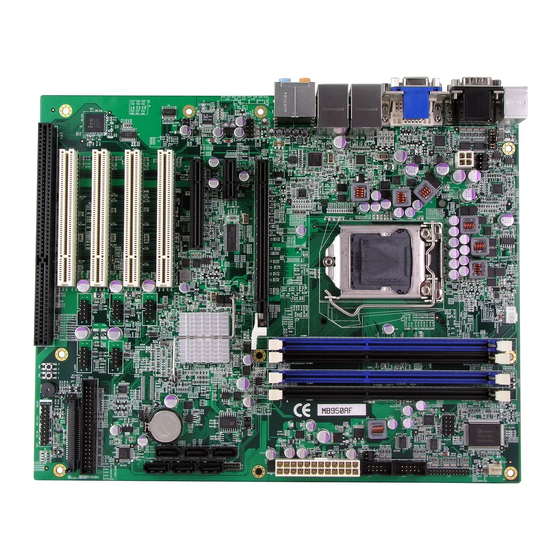
INTRODUCTION Introduction Product Description The MB950 ATX motherboard offers the latest Socket H (LGA1156) supporting the Intel® Core™ i7, Core™ i5, Core™ i3 processors or the Intel® Pentium® processor G6950, all developed on Intel’s newest microarchitecture, formerly codenamed “Nehalem,” and using Intel’s 32nm and 45nm process technologies. -
Page 6: Checklist
INTRODUCTION Checklist Your MB950 package should include the items listed below. • • • • The MB950 ATX motherboard • • • • This User’s Manual • • • • 1 CD containing chipset drivers and flash memory utility • • • • Cable kit (IDE, Serial ATA) -
Page 7: Mb950 Specifications
2 x 4 pins header for Digital I/O 5-pin header x 1 for IrDA 26-pin header x 1 for Parallel Watchdog Timer Yes (256 segments, 0, 1, 2…255 sec/min) System Voltage +5V, +3.3V, +12V, -12V, 5VSB Other LAN Wakeup Board Size 305mm x 244mm MB950 User’s Manual... -
Page 8: Board Dimensions
INTRODUCTION Board Dimensions MB950 User’s Manual... -
Page 9: Installations
INSTALLATIONS Installations This section provides information on how to use the jumpers and connectors on the MB950 in order to set up a workable system. The topics covered are: Installing the CPU.................. 6 Installing the Memory................7 Setting the Jumpers................8 Connectors on MB950................. -
Page 10: Installing The Cpu
INSTALLATIONS Installing the CPU The MB950 board supports an LGA1156 Socket (shown below) for Intel Clarkdale processors. To install the CPU, unlock first the socket by pressing the lever sideways, then lift it up to a 90-degree. Then, position the CPU above the socket such that the CPU corner aligns with the gold triangle matching the socket corner with a small triangle. -
Page 11: Installing The Memory
INSTALLATIONS Installing the Memory The MB950 board supports four DDR3 memory socket for a maximum total memory of 16GB in DDR3 DIMM memory type. Installing and Removing Memory Modules To install the DDR3 modules, locate the memory slot on the board and perform the following steps: 1. -
Page 12: Setting The Jumpers
INSTALLATIONS Setting the Jumpers Jumpers are used on MB950 to select various settings and features according to your needs and applications. Contact your supplier if you have doubts about the best configuration for your needs. The following lists the connectors on MB950 and their respective functions. -
Page 13: Jumper Locations On Mb950
INSTALLATIONS Jumper Locations on MB950 Jumpers on MB950................Page JP1, JP2, JP3: RS232/RS422/RS485 (COM1) Selection ....10 JP4: COM1 RS232 RI/+5V/+12V Power Setting........ 10 JP5: COM3 RS232 RI/+5V/+12V Power Setting........ 10 JP9: COM4 RS232 RI/+5V/+12V Power Setting........ 10 JP11: COM2 RS232 RI/+5V/+12V Power Setting......11 JP7: Compact Flash Socket Master/Slave Setting........ -
Page 14: Jp1, Jp2, Jp3: Rs232/Rs422/Rs485 (Com1) Selection
Short/Closed JP5: COM3 RS232 RI/+5V/+12V Power Setting Setting Function Pin 1-2 +12V Short/Closed Pin 3-4 Short/Closed Pin 5-6 Short/Closed JP9: COM4 RS232 RI/+5V/+12V Power Setting Setting Function Pin 1-2 +12V Short/Closed Pin 3-4 Short/Closed Pin 5-6 Short/Closed MB950 User’s Manual... -
Page 15: Jp11: Com2 Rs232 Ri/+5V/+12V Power Setting
Setting Function Pin 1-2 +12V Short/Closed Pin 3-4 Short/Closed Pin 5-6 Short/Closed JP7: Compact Flash Socket Master/Slave Setting Compact Flash Master Slave JP8: Clear CMOS Contents Setting Function Pin 1-2 Normal Short/Closed Pin 2-3 Clear CMOS Short/Closed MB950 User’s Manual... -
Page 16: Connectors On Mb950
INSTALLATIONS Connectors on MB950 Connector Locations on MB950 ............13 CN1: PS/2 Keyboard and PS/2 Mouse Connectors......14 CN3: COM1 and COM3 Serial Ports........... 14 CN2: VGA and DVI ................15 CN5: Gigabit LAN (82583V) + USB2/USB3 ........15 CN6: Gigabit LAN (82578DM) + USB0/USB1 ........15 CN4: HD Audio Connector.............. -
Page 17: Connector Locations On Mb950
INSTALLATIONS Connector Locations on MB950 Connector Locations on MB950..........................Page CN1: PS/2 Keyboard and PS/2 Mouse Connectors ...................... 14 CN3: COM1 and COM3 Serial Ports........................... 14 CN2: VGA and DVI..............................15 CN5: Gigabit LAN (82583V) + USB2/USB3 ......................15 CN6: Gigabit LAN (82578DM) + USB0/USB1......................15 CN4: HD Audio Connector ............................ -
Page 18: Cn1: Ps/2 Keyboard And Ps/2 Mouse Connectors
PS/2 Keyboard Signal Name Keyboard Mouse Signal Name Keyboard data Mouse data N.C. N.C. Keyboard clock Mouse clock N.C. N.C. CN3: COM1 and COM3 Serial Ports Pin # Signal Name RS-232 R2-422 RS-485 DATA- DATA+ Ground Ground Ground MB950 User’s Manual... -
Page 19: Cn2: Vga And Dvi
Pin # Pin # Signal Name DATA2- DATA2+ N.C. N.C. DDCCLK DDCDATA N.C. DATA1- DATA1+ N.C. N.C. Hot Plug Detect DATA0- DATA0+ N.C. N.C. CLK+ CLK- CN5: Gigabit LAN (82583V) + USB2/USB3 CN6: Gigabit LAN (82578DM) + USB0/USB1 MB950 User’s Manual... -
Page 20: Cn4: Hd Audio Connector
J2 : Audio Pin Header for Chassis Front Panel Signal Name Signal Name MIC IN_L Ground MIC IN_R LINE_R Ground Sense LINE_L Ground J3: ATX 12V Power Connector This connector supplies the CPU operating voltage. Pin # Signal Name Ground Ground +12V +12V MB950 User’s Manual... -
Page 21: J19: 24-Pin Atx Power Connector
+12V +12V Ground +3.3V J11 : Digital I/O Connector (4 in, 4 out) Signal Name Pin # Pin # Signal Name Ground Out3 Out1 Out2 Out0 J12 : IRDA Connector Pin # Signal Name SOUTB SINB VCC5 MB950 User’s Manual... -
Page 22: J13: Front Panel Function Connector
J16, J17, J18, J22, J23, J24: SATA II Connectors Pin # Signal Name Ground Ground Ground J20, J21: COM4, COM2 RS232 Serial Ports Signal Name Pin # Pin # Signal Name DCD# DSR# SIN# RTS# SOUT CTS# DTR# MB950 User’s Manual... -
Page 23: F_Usb1: Usb4/Usb5 Connector
PD6, parallel data 6 Ground PD7, parallel data 7 Ground ACK, acknowledge Ground Busy Ground Paper empty Ground Select F_USB1: USB4/USB5 Connector Signal Name Signal Name F_USB2: USB6/USB7 Connector F_USB3: USB8/USB9 Connector F_USB4: USB10/USB11 Connector F_USB5: USB12/USB13 Connector MB950 User’s Manual... -
Page 24: Cpu_Fan1: Cpu Fan Power Connector
SYS_FAN1: system Fan1 Power Connector Pin # Signal Name Ground +12V Rotation detection CN7: CF Socket J4: ISA Slot (shared with PCI4) PCIE1: PCI-E X16 (PEG) PCIE2: PCI-E X1 Slot PCIE3: PCI-E X8 Slot (X4 Link) PCI1-PCI4: PCI 32-bit Slot MB950 User’s Manual... -
Page 25: Bios Setup
..................23 Advanced Settings ..................24 PCIPnP Settings .................... 35 Boot Settings ....................37 Security Settings ................... 38 Advanced Chipset Settings ................39 Exit Setup ....................... 42 Load Optimal Defaults ................. 42 Load Failsafe Defaults ................. 42 MB950 User’s Manual... -
Page 26: Bios Introduction
<PgUp> and <PgDn> keys to change entries, <F1> for help and <Esc> to quit. When you enter the Setup utility, the Main Menu screen will appear on the screen. The Main Menu allows you to select from various setup functions and exit choices. MB950 User’s Manual... -
Page 27: Main Bios Setup
These defaults have been carefully chosen by both AMI and your system manufacturer to provide the absolute maximum performance and reliability. Changing the defaults could cause the system to become unstable and crash in some cases. MB950 User’s Manual... -
Page 28: Advanced Settings
Ratio CMOS Setting MPS and ACPI MADT ordering Modern ordering General Help Max CPUID Value Limit Disabled F10 Save and Exit Intel(R) Virtualization Tech Enabled ESC Exit Intel(R) HT Technology Enabled Active Processor Cores A20M Diabled ►Intel PPM Configuration MB950 User’s Manual... - Page 29 Intel Vitualization Tech. Note: A full reset is required to change the setting. Intel HT Technology When disabled, only one thread per enabled core is enabled. Active Processor Cores Number of cores to enable in each processor package. A20M Legacy OSes and Aps may need A20 M enabled. MB950 User’s Manual...
- Page 30 When enabled, CPU will conditionally demote C3/C6/C7 requests to C1 based on uncore auto-demote information. C1 Auto Demotion / C3 Auto Demotion When enabled, CPU will conditionally demote C6/C7 requests to C3 based on uncore auto-demote information. MB950 User’s Manual...
-
Page 31: Hard Disk Write Protect
BIOS. IDE Detect Time Out (Sec) Select the time out value for detecting ATA/ATAPI device(s). ATA(PI) 80pin Cable Detection Select the mechanism for detecting 80pin ATA(PI) cable. Jmicron 36x ATA Controller Select ATA Controller Operate Mode MB950 User’s Manual... -
Page 32: Parallel Port Mode
This field sets the system power status whether on or off when power returns to the system from a power failure situation. Power On Function This field is related to how the system is powered on . The options are None, Mouse Left, Mouse Right, and Any Key. MB950 User’s Manual... -
Page 33: Acpi Shutdown Temperature
The Hardware Health Configuration menu is used to show the operating temperature, fan speeds and system voltages. CPU smart fan The options are Disabled, 55ºC, 60ºC, 65ºC, 70ºC,755ºC, 80ºC, and 85ºC. ACPI Shutdown Temperature The options are Disabled, 70ºC/158ºF, 75ºC/167ºF, 80ºC/176ºF, 85ºC/185ºF, 90ºC/194ºF, and 95ºC/203ºF. MB950 User’s Manual... -
Page 34: Suspend Mode
Tab Select Field General Help F10 Save and Exit ESC Exit Suspend Mode The options of this field are S1, S3 and Auto. Repost Video on S3 Resumet Determines whether to invoke VGA BIOS post on S3/STR resume. MB950 User’s Manual... - Page 35 Change Field Tab Select Field General Help F10 Save and Exit ESC Exit The Intel AMT Configuration configures the Intel Active Management Technology (AMT) options. Intel AMT Configuration REMARKS: The is available only on MB950AF, not MB950F. MB950 User’s Manual...
-
Page 36: Mps Version Control For Os
This option is specifies the MPS (Multiprocessor Specification) version for your operating system. MPS version 1.4 added extended configuration tables to improve support for multiple PCI bus configurations and improve future expandability. The default setting is 1.4. MB950 User’s Manual... -
Page 37: Redirection After Bios Post
Always: Redirection is always active. (Some OSs may not work if set to Always.) Terminal Type - Select the target terminal type. VT-UTF8 Combo Key Support – Enable VT-UTF8 Combination Key Support for ANSI/VT100 terminals. Sredir Memory Display Delay – Gives the delay in seconds to display memory information. MB950 User’s Manual... -
Page 38: Usb Configuration
Legacy USB Support Enables support for legacy USB. AUTO option disables legacy support if no USB devices are connected. Legacy USB1.1 HC Support Support USB 1.1 HC. USB Beep Message Enables the beep during USB device enumeration. MB950 User’s Manual... -
Page 39: Pcipnp Settings
PnP devices not required for boot if your system has a Plug and Play OS. PCI Latency Timer This item sets value in units of PCI clocks for PCI device latency timer register. Options are: 32, 64, 96, 128, 160, 192, 224, 248. MB950 User’s Manual... -
Page 40: Palette Snooping
AUTO: Works for most PCI IDE cards. IRQ# Use the IRQ# address to specify what IRQs can be assigned to a particular peripheral device Reserved Memory Size Size of memory block to reserve for legacy ISA devices. MB950 User’s Manual... -
Page 41: Boot Settings
Boot Device Priority This specifies the boot sequence from the available devices. A device enclosed in parenthesis has been disabled in the corresponding type menu. Hard Disk Drives This specifies the Boot Device Priority sequence from available Hard Drives. MB950 User’s Manual... -
Page 42: Security Settings
<- Select Screen Change Supervisor Password ↑ ↓ Select Item ↑ ↓ ↑ ↓ ↑ ↓ Change User Password Change Field Tab Select Field Boot Sector Virus Protection [Disabled] General Help F10 Save and Exit ESC Exit MB950 User’s Manual... -
Page 43: Advanced Chipset Settings
Memory Remap Feature This allows remapping of overlaped PCI memory above the total physical memory. DRAM Frequency The options are Auto, 1067 MHz and 1333 MHz. Configure DRAM Timing by SPD The options are Auto and Manual. MB950 User’s Manual... -
Page 44: Memory Hole
Video Function Configuration DVMT Mode DVMT Mode Select [DVMT Mode] DVMT/FIXED Memory [256MB] <- Select Screen ↑ ↓ Select Item ↑ ↓ ↑ ↓ ↑ ↓ Change Field Tab Select Field General Help F10 Save and Exit ESC Exit MB950 User’s Manual... - Page 45 PCIPnP Boot Security Exit ME Subsystem Configuration <- Select Screen ↑ ↓ ↑ ↓ Select Item ↑ ↓ ↑ ↓ Management Engine Version : Change Field Tab Select Field General Help F10 Save and Exit ESC Exit MB950 User’s Manual...
-
Page 46: Exit Setup
These default settings are optimal and enable all high performance features. Load Failsafe Defaults This option allows you to load the troubleshooting default values permanently stored in the BIOS ROM. These default settings are non-optimal and disable all high-performance features. MB950 User’s Manual... -
Page 47: Drivers Installation
LAN Drivers Installation ..............49 Intel® Management Engine Interface ..........51 IMPORTANT NOTE: After installing your Windows operating system (Windows 2000/XP/Vista), you must install first the Intel Chipset Software Installation Utility before proceeding with the drivers installation. MB950 User’s Manual... -
Page 48: Intel Chipset Software Installation Utility
3. When the Welcome screen appears, click Next to continue. 4. Click Yes to accept the software license agreement and proceed with the installation process. 5. On the Readme Information screen, click Next to continue the installation. MB950 User’s Manual... - Page 49 DRIVERS INSTALLATION 6. When the Setup Progress screen appears, click Next to continue. 7. The Setup process is now complete. Click Finish then restart the computer and for changes to take effect. MB950 User’s Manual...
-
Page 50: Intel Graphics Driver Installation
1. Insert the DVD that comes with the board. Click Intel -> Intel® Q57 Chipset Family Graphics Driver. 2. When the InstallShield Wizard screen appears, click Next. 3. When the Welcome screen appears, click Next to continue. MB950 User’s Manual... - Page 51 5. On Readme File Information screen, click Next to continue. 6. On Setup Progress screen, click Next to continue the installation. 7. The Setup process is now complete. Click Finish to restart the computer and for changes to take effect. MB950 User’s Manual...
-
Page 52: Realtek Hd Codec Audio Driver Installation
High Definition Audio Driver. 2. Click Realtek High Definition Codec Audio Driver. 3. When the Welcome screen appears, click Next to continue. 4. The Setup process is now complete. Restart the computer when prompted for changes to take effect. MB950 User’s Manual... -
Page 53: Lan Drivers Installation
4. When the Welcome screen appears, click Next to continue. 5. In the License Agreement screen, click I accept the terms in license agreement and Next to accept the software license agreement and proceed with the installation process. MB950 User’s Manual... - Page 54 Next to continue. 7. When the Ready to Install the Program screen appears, click Install to continue. 8. The Setup process is now complete (InstallShield Wizard Completed). Click Finish to restart the computer and for changes to take effect. MB950 User’s Manual...
-
Page 55: Intel® Management Engine Interface
1. Insert the drivers disc that comes with the motherboard. Click Intel and then Intel(R) AMT 6.0 Drivers. When the welcome screen of the Intel® Management Engine Components appears, click Next to continue. On the next screen, click Next to agree to the license agreement. MB950 User’s Manual... - Page 56 DRIVER INSTALLATION 2. On the next screen, the Readme File Information shows the system requirements and installation information, click Next. MB950 User’s Manual...
- Page 57 DRIVERS INSTALLATION 3. When the Setup Progress screen appears, click Next to continue. Then, click Finish when the setup progress has been successfully installed to restart the computer. MB950 User’s Manual...
- Page 58 DRIVER INSTALLATION This page is intentionally left blank. MB950 User’s Manual...
-
Page 59: Appendix
Serial Port #4(COM4) 2F8h - 2FFh Serial Port #2(COM2) 2B0 - 2DF Graphics adapter Controller 3C0 - 3CF EGA adapter 3D0 - 3DF CGA adapter 3E8h – 3EFh Serial Port #3(COM3) 3F8h - 3FFh Serial Port #1(COM1) MB950 User’s Manual... -
Page 60: Interrupt Request Lines (Irq)
Interrupt Cascade IRQ3 Serial Port #2, 4 IRQ4 Serial Port #1, 3 IRQ5 Reserved IRQ6 Reserved IRQ8 Real Time Clock IRQ9 Reserved IRQ10 Reserved IRQ11 Reserved IRQ12 PS/2 Mouse IRQ13 80287 IRQ14 Primary IDE IRQ15 Secondary IDE MB950 User’s Manual... -
Page 61: Watchdog Timer Configuration
= strtol (argv[1], endptr, 10); printf("System will reset after %d seconds\n", bTime); if (bTime) EnableWDT(bTime); else DisableWDT(); return 0; //--------------------------------------------------------------------------- void EnableWDT(int interval) unsigned char bBuf; bBuf = Get_F81865_Reg(0x2B); bBuf &= (~0x20); Set_F81865_Reg(0x2B, bBuf); //Enable WDTO MB950 User’s Manual... - Page 62 = F81865_BASE; ucDid = Get_F81865_Reg(0x20); if (ucDid == 0x07) //Fintek 81865 goto Init_Finish; } F81865_BASE = 0x2E; result = F81865_BASE; ucDid = Get_F81865_Reg(0x20); if (ucDid == 0x07) //Fintek 81865 goto Init_Finish; } F81865_BASE = 0x00; result = F81865_BASE; MB950 User’s Manual...
- Page 63 (F81865_BASE) #define F81865_DATA_PORT (F81865_BASE+1) //--------------------------------------------------------------------------- #define F81865_REG_LD 0x07 //--------------------------------------------------------------------------- #define F81865_UNLOCK 0x87 #define F81865_LOCK 0xAA //--------------------------------------------------------------------------- unsigned int Init_F81865(void); void Set_F81865_LD( unsigned char); void Set_F81865_Reg( unsigned char, unsigned char); unsigned char Get_F81865_Reg( unsigned char); //--------------------------------------------------------------------------- #endif //__F81865_H MB950 User’s Manual...
- Page 64 APPENDIX MB950 User’s Manual...
Need help?
Do you have a question about the MB950 and is the answer not in the manual?
Questions and answers