
Related Manuals for IBASE Technology MB898


Summary of Contents for IBASE Technology MB898
- Page 1 MB898/MB898F/ MB898RF Socket LGA775 Pentium ® Intel Q965 Chipset ® Industrial Motherboard USER’S MANUAL Version 1.0...
- Page 2 Award is a registered trademark of Award Software International, Inc. PS/2 is a trademark of International Business Machines Corporation. Intel and Pentium 4 are registered trademarks of Intel Corporation. Microsoft Windows is a registered trademark of Microsoft Corporation. Winbond is a registered trademark of Winbond Electronics Corporation.
-
Page 3: Table Of Contents
Watchdog Timer Configuration ... 24 BIOS Setup ... 29 Drivers Installation Intel Q965 Chipset Software Installation Utility ... 50 Intel Q965 Chipset Graphics Driver ... 52 Realtek Codec Audio Driver Installation ... 54 Intel LAN Drivers Installation ... 55 Appendix ... - Page 4 This page is intentionally left blank. MB898 User’s Manual...
-
Page 5: Introduction
Introduction Checklist Your MB898/MB898F Pentium the items listed below: • The MB898/MB898F motherboard • This User’s manual • 1 Back I/O shield • 1 IDE cable • 1 Floppy cable • 1 SATA cable • 1 Serial-Port cable • 1 CD containing the following: •... -
Page 6: Product Description
Product Description ® The MB898/MB898F LGA 775 Pentium 4 motherboard incorporates the Intel Q965 chipset that can utilize a single LGA775 processor of up to 4.0GHz or higher and supports FSB frequency of 533/800/1066Mhz (133MHz(533MT/s), 200MHz(800MT/s) and 266MHz(1066MT/s) HCLK respectively. -
Page 7: Specifications
Storage Temperature -20°C~80°C (-68°F~176°F) Relative Humidity 10%~90% (non-condensing) Remarks: MB898/MB898F supports Intel Core 2 Duo Dual Core CPU, Pentium® D Dual Core CPU and Pentium® 4 HT single core CPU. It also supports EMT64 processors. MB898 User’s Manual ® Q965 Chipset ®... -
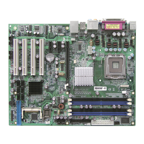
Page 8: Board Dimensions
INSTALLATIONS Board Dimensions MB898 User’s Manual... -
Page 9: Installations
Installations This section provides information on how to use the jumpers and connectors on the MB898/MB898F in order to set up a workable system. The topics covered are: Installing the CPU ... 6 ATX Power Installation ... 6 Installing the Memory ... 7 Setting the Jumpers ... -
Page 10: Installing The Cpu
INSTALLATIONS Installing the CPU The MB898/MB898F motherboard supports an LGA 775 processor socket for Intel® Pentium® 4 processors. The LGA 775 processor socket comes with a lever to secure the processor. Refer to the pictures below, from left to right, on how to place the processor into the CPU socket. -
Page 11: Installing The Memory
Dual Channel Memory Configuration If you want to operate the Dual Channel Technology, please note the following explanations due to the limitation of Intel chipset specifications. 1. Dual Channel mode will not be enabled if only one DDR II memory module is installed. -
Page 12: Setting The Jumpers
INSTALLATIONS Setting the Jumpers Jumpers are used on MB898/MB898F to select various settings and features according to your needs and applications. Contact your supplier if you have doubts about the best configuration for your needs. The following lists the connectors on MB898/MB898F and their respective functions. - Page 13 INSTALLATIONS Jumper Locations on MB898/MB898F Jumper Locations on MB898/MB898F ... 9 JP8, JP9, JP10: RS232/422/485 (COM2) Selection ... 10 JP6: IDE DMA Mode Setting... 11 JBAT1: Clear CMOS Contents ... 10 JP1: Boot Device Selection………………..……………………..11 JP5: Configure and Recovery…………………………………… 11 JP11: Processor Setting ...
- Page 14 ATX-power connector should be disconnected from the motherboard before clearing CMOS. JBAT1 JP1: Select the Boot Device (Factory used only) JP5: Configure and Recovery (Factory use only) JBAT1 MB898 User’s Manual Setting Pin 1-2 Short/Closed Pin 2-3 Clear CMOS Short/Closed...
- Page 15 RS-232 use only. The following table describes the jumper settings for COM2 selection. COM2 Function Jumper Setting (pin closed) JP11: Processor Setting JP11 MB898 User’s Manual Setting Pin 1-2 Master (default) Short/Closed Pin 1-2 Open RS-232 RS-422...
-
Page 16: Connectors On Mb898
The connectors on MB898/MB898F allows you to connect external devices such as keyboard, floppy disk drives, hard disk drives, printers, etc. The following table lists the connectors on MB898 and their respective functions. ATX1: 24-pin ATX Power Connector ... 14 ATX2: ATX 12V Power Connector ... - Page 17 CN3: PS/2 Keyboard and PS/2 Mouse Connectors ...16 CN4: Audio Connector ...17 USB6: USB6/7 Connector ...17 USB_LAN1: 10/100 or GbE RJ-45 and USB4/5 Connector ...17 Note: 10/100 LAN for MB898; Gigabit LAN for MB898F ...17 F_USB1: USB0/USB1 Connector ...17 F_USB2: USB2/USB3 Connector ...18 F_USB3: USB8/USB9 Connector ...18 S_ATA1,S_ATA2,S_ATA3,S_ATA4,S_ATA5,S_ATA6: SATA0/1/2/3/4/5 Connector ...18...
-
Page 18: Atx1: 24-Pin Atx Power Connector
-12V Ground PS-ON Ground Ground Ground Ground ATX2: ATX 12V Power Connector Signal Name +12V +12V +12V +12V MB898/MB898F Edge Connectors MB898 User’s Manual Pin # Pin # Signal Name 3.3V 3.3V Ground Ground Ground Power good 5VSB +12V +12V +3.3V... -
Page 19: Vga1: Vga Crt Connector
PD3, parallel data 3 PD4, parallel data 4 PD5, parallel data 5 PD6, parallel data 6 PD7, parallel data 7 ACK, acknowledge Busy Paper empty Select MB898 User’s Manual Pin # Blue N.C. HSYNC DDCCLK CN1 Parallel Port Pin # Pin #... -
Page 20: Cn2, J10, J6, J5: Com1/2/3/4 Serial Ports
COM2 is jumper selectable for RS-232, RS-422 and RS-485. Pin # RS-232 Ground CN3: PS/2 Keyboard and PS/2 Mouse Connectors Mouse (top) Keyboard clock Keyboard (bottom) MB898 User’s Manual COM2 Pin # Pin # DSR, Data set ready RTS, Request to send Signal Name R2-422... -
Page 21: Cn4: Audio Connector
CN4: Audio Connector USB6: USB6/7 Connector USB_LAN1: 10/100 or GbE RJ-45 and USB4/5 Connector Note: 10/100 LAN for MB898; Gigabit LAN for MB898F/MB898RF F_USB1: USB0/USB1 Connector Signal Name MB898 User’s Manual Ground INSTALLATIONS Signal Name Ground Ground... -
Page 22: F_Usb2: Usb2/Usb3 Connector
INSTALLATIONS F_USB2: USB2/USB3 Connector Signal Name F_USB3: USB8/USB9 Connector Signal Name S_ATA1,S_ATA2,S_ATA3,S_ATA4,S_ATA5,S_ATA6: SATA0/1/2/3/4/5 Connector Note: S_ATA5 and S_ATA6 MB898F only MB898 User’s Manual Ground Ground Pin # Signal Name Ground Ground Ground Signal Name Ground Ground Signal Name Ground Ground... -
Page 23: Ide1: Primary Ide Connectors
IOCHRDY DACK0 IRQ14 Address 1 IDE1 Address 0 Chip select 0 Activity CPU_FAN1: CPU Fan Power Connector PWR_FAN1: POWER Fan Power Connector MB898 User’s Manual Pin # Pin # Pin # Signal Name Control Sense +12V Ground Pin # Signal Name... -
Page 24: Sys_Fan1: System Fan Power Connector
Sense Line2_R J2: HDMI Audio Connector J2 is a HDMI Audio connector. The following table shows the pin-out assignments of this connector. Signal Name ACZ_RST ACZ_SYNC MB898 User’s Manual Pin # Signal Name Control Sense +12V Ground Pin # Signal Name... -
Page 25: J8: System Function Connector
Switch” on the system that connects to the power switch on the case. When pressed, the power switch will force the system to power on. When pressed again, it will force the system to power off. MB898 User’s Manual INSTALLATIONS Pin # Signal Name... -
Page 26: J11: Irda Connector
Hard Disk Drive LED Connector: Pins 10 and 20 This connector connects to the hard drive activity LED on control panel. This LED will flash when the HDD is being accessed. J11: IrDA Connector MB898 User’s Manual Pin # Signal Name HDD Active Pin #... -
Page 27: J12: Digital I/O Connector (4 In, 4 Out)
ON/OFF circuitry. Signal Name Ground Out3 Out2 PCIE_1: x16 PCI Express Slot PCIE_2, PCIE_3: x1 PCI Express Slots PCI1, PCI2, PCI3, PCI4: PCI Slots J9: CF Socket MB898 User’s Manual INSTALLATIONS Pin # Pin # Signal Name Out1 Out0... -
Page 28: Watchdog Timer Configuration
**endptr; copyright(); if (argc != 2) printf(" Parameter incorrect!!\n"); return 1; if (Init_W627EHF() == 0) printf(" Winbond 83627HF is not detected, program abort.\n"); return 1; bTime = strtol (argv[1], endptr, 10); MB898 User’s Manual... - Page 29 Set_W627EHF_Reg( 0xF5, bBuf); Set_W627EHF_Reg( 0xF6, interval); //======================================================================= void DisableWDT(void) Set_W627EHF_LD(0x08); Set_W627EHF_Reg(0xF6, 0x00); Set_W627EHF_Reg(0x30, 0x00); //======================================================================= MB898 User’s Manual INSTALLATIONS //Enable WDTO //switch to logic device 8 //enable timer //count mode is second //set timer //switch to logic device 8 //clear watchdog timer...
- Page 30 Init_Finish; } W627EHF_BASE = 0x00; result = W627EHF_BASE; Init_Finish: return (result); //======================================================================= void Unlock_W627EHF (void) outportb(W627EHF_INDEX_PORT, W627EHF_UNLOCK); outportb(W627EHF_INDEX_PORT, W627EHF_UNLOCK); //======================================================================= ==== void Lock_W627EHF (void) outportb(W627EHF_INDEX_PORT, W627EHF_LOCK); //======================================================================= void Set_W627EHF_LD( unsigned char LD) Unlock_W627EHF(); outportb(W627EHF_INDEX_PORT, W627EHF_REG_LD); outportb(W627EHF_DATA_PORT, LD); MB898 User’s Manual...
- Page 31 W627EHF_DATA_PORT //======================================================================= #define W627EHF_REG_LD //======================================================================= #define W627EHF_UNLOCK #define W627EHF_LOCK //======================================================================= unsigned int Init_W627EHF(void); void Set_W627EHF_LD( unsigned char); void Set_W627EHF_Reg( unsigned char, unsigned char); unsigned char Get_W627EHF_Reg( unsigned char); //======================================================================= #endif //__W627EHF_H MB898 User’s Manual (W627EHF_BASE) (W627EHF_BASE+1) 0x07 0x87 0xAA INSTALLATIONS...
- Page 32 = ucBuf; printf("Digital I/O Input Changed. Current Data is 0x%X\n",ucDI); if (kbhit()) getch(); break; delay(500); return 0; //===================================================================== void ClrKbBuf(void) while(kbhit()) getch(); //--------------------------------------------------------------------------- MB898 User’s Manual //data for digital output //data for digital input //switch to logic device 7 //clear...
-
Page 33: Bios Setup
PC Health Status ... 46 Frequency/Voltage Control ... 47 Load Fail-Safe Defaults ... 48 Load Optimized Defaults ... 48 Set Supervisor/User Password ... 48 Save & Exit Setup ... 48 Exit Without Saving ... 48 MB898 User’s Manual BIOS SETUP... -
Page 34: Bios Introduction
BIOS Introduction The Award BIOS (Basic Input/Output System) installed in your computer system’s ROM supports Intel processors. The BIOS provides critical low-level support for a standard device such as disk drives, serial ports and parallel ports. It also adds virus and password protection as well as special support for detailed fine-tuning of the chipset controlling the entire system. - Page 35 Award and your system manufacturer to provide the absolute maximum performance and reliability. Changing the defaults could cause the system to become unstable and crash in some cases. MB898 User’s Manual BIOS SETUP Frequency/Voltage Control Load Fail-Safe Defaults...
-
Page 36: Standard Cmos Setup
Day : Sun to Sat Month : 1 to 12 Date : 1 to 31 Year : 1999 to 2099 MB898 User’s Manual Standard CMOS Features Fri, Oct 20, 2006 16 : 11 : 00 None None None None None None 1.44M, 3.5 in. - Page 37 IDE Channel Master/Slave MB898F with ICH8R supports 6 Serial ATA connectors, while MB898 with ICH8 supports 4 Serial ATA connectors; MB898 series boards with JMicron controller support 1 CF and 1 IDE connectors. The onboard Serial ATA connectors provide Primary and Secondary channels for connecting up to four Serial ATA hard disks .
- Page 38 This field determines whether or not the system will halt if an error is detected during power up. No errors All errors All, But Keyboard All, But Diskette All, But Disk/Key MB898 User’s Manual 720KB 1.44MB 3.5 in. 3.5 in. For EGA, VGA, SEGA, SVGA or PGA monitor adapters. (default) Power up in 40 column mode.
-
Page 39: Hard Disk Boot Priority
DRAM into cache memory, for even faster access by the CPU. These items allow you to enable (speed up memory access) or disable the cache function. By default, these items are Enabled. MB898 User’s Manual Advanced BIOS Features Press Enter... - Page 40 Hyper-Threading Technology enables two logical processors on a single physical processor by replicating, partitioning, and sharing the resources within the Intel NetBurst microarchitecture pipeline. Quick Power On Self Test When enabled, this field speeds up the Power On Self Test (POST) after the system is turned on.
-
Page 41: Apic Mode
If you set this feature to Disabled, the BIOS will not report the missing floppy drive to Win95/98. Small Logo (EPA) Show The EPA logo appears at the right side of the monitor screen when the system is boot up. The default setting is Disabled. MB898 User’s Manual... -
Page 42: System Bios Cacheable
The fields under the On-Chip VGA Setting and their default settings are: PEG/On Chip VGA Control: Auto On-Chip Frame Buffer Size: 8MB DVMT Mode: DVMT DVMT/Fixed Memory Size: 128MB MB898 User’s Manual Advanced Chipset Features Enabled Disabled Press Enter Auto... -
Page 43: Integrated Peripherals
Use IR Pins Onboard Parallel Port Parallel Port Mode EPP Mode Select ECP Mode Use DMA Phoenix - AwardBIOS CMOS Setup Utility Intel 82562V LAN Control MB898 User’s Manual Integrated Peripherals Press Enter Press Enter Press Enter Menu Level >... -
Page 44: Onchip Secondary Pci Ide
IDE Primary/Secondary Master/Slave UDMA These fields allow your system to improve disk I/O throughput to 33Mb/sec with the Ultra DMA/33 feature. The options are Auto and Disabled. MB898 User’s Manual Super IO Device 3E8h IRQ11 Menu Level >... -
Page 45: Sata Mode
Serial Port 3 3E8/IRQ11 Serial Port 4 2E8/IRQ10 Parallel Port 378H/IRQ7 UART Mode Select This field determines the UART 2 mode in your computer. The default value is Normal. Other options include IrDA and ASKIR. MB898 User’s Manual BIOS SETUP... - Page 46 ECP+EPP Combination of ECP and EPP capabilities Normal Normal function Intel 82562V LAN Control (MB898) By default, this setting is Enabled. USB 1.0 Controller The options for this field are Enabled and Disabled. By default, this field is set to Enabled.
-
Page 47: Acpi Function
This field allows you to select the type of power saving management modes. There are four selections for Power Management. Min. Power Saving Max. Power Saving User Define MB898 User’s Manual Power Management Setup Enabled S1(POS) User Define Menu Level >... -
Page 48: Soft-Off By Pwrbtn
IRQ to occur. When the operating system is ready to respond to the request, it interrupts itself and performs the service. MB898 User’s Manual Default setting, blank the screen and turn off vertical and horizontal scanning. -
Page 49: Reset Configuration Data
MPEG ISA/VESA VGA card. When this field is disabled, a PCI/VGA cannot work with an MPEG ISA/VESA card. Maximum Payload Size The default setting of the PCI Express Maximum Payload Size is 128. MB898 User’s Manual PnP/PCI Configurations PCI Slot Disabled... -
Page 50: Cpu Warning Temperature
Temperatures/Fan Speeds/Voltages These fields are the parameters of the hardware monitoring function feature of the board. The values are read-only values as monitored by the system and show the PC health status. MB898 User’s Manual PC Health Status Disabled Disabled 32°C/89°F... -
Page 51: Spread Spectrum
This field enables or disables the auto detection of the PCI clock. Spread Spectrum This field sets the value of the spread spectrum. The default setting is Disabled. This field is for CE testing use only MB898 User’s Manual Frequency/Voltage Control Disabled Disabled Menu Level >... -
Page 52: Load Fail-Safe Defaults
Select this option to exit the Setup utility without saving the changes you have made in this session. Typing “Y” will quit the Setup utility without saving the modifications. Typing “N” will return you to Setup utility. MB898 User’s Manual... -
Page 53: Drivers Installation
Realtek Codec Audio Driver Installation . 錯誤! 尚未定義書籤。 Intel LAN Drivers Installation ... 錯誤! 尚未定義書籤。 IMPORTANT NOTE: After installing your Windows operating system (Windows 2000/XP), you must install first the Intel Chipset Software Installation Utility before proceeding with the drivers installation. MB898 User’s Manual DRIVERS INSTALLATION... -
Page 54: Intel Q965 Chipset Software Installation Utility
Intel Q965 Chipset Software Installation Utility The Intel® Q965 Chipset Drivers should be installed first before the software drivers to enable Plug & Play INF support for Intel chipset components. Follow the instructions below to complete the installation under Windows 2000/XP. (Before installed Intel Chipset Software... - Page 55 3. Click Yes to accept the software license agreement and proceed with the installation process. 4. On the Readme Information screen, click Next to continue the installation. 5. The Setup process is now complete. Click Finish to restart the computer and for changes to take effect. MB898 User’s Manual...
-
Page 56: Intel Q965 Chipset Graphics Driver
Windows 2000/XP. 1. Insert the CD that comes with the board and the screen below would appear. Click Intel (R) Q965 Chipset Drivers, then Intel (R) Q965 Chipset Family Graphics Driver. 2. When the Welcome screen appears, click Next to continue. - Page 57 4. On Readme File Information screen, click Next to continue. 5. On Setup Progress screen, click Next to continue the installation. 6. The Setup process is now complete. Click Finish to restart the computer and for changes to take effect. MB898 User’s Manual...
-
Page 58: Realtek Codec Audio Driver Installation
Realtek Codec Audio Driver Installation 1. Insert the CD that comes with the board and the screen below would appear. Click Intel (R) Q965 Chipset Drivers, then Realtek High Definition Codec Audio Driver. 2. When the Welcome screen appears, click Next to continue. -
Page 59: Intel Lan Drivers Installation
DRIVERS INSTALLATION Intel LAN Drivers Installation Follow the steps below to start installing the Intel PCI Express Gigabit LAN drivers. 1. Insert the CD that comes with the board. On the initial screen, Click Intel (R) Q965 Chipset Drivers, then Intel(R) PRO LAN Network Drivers. - Page 60 5. When the Setup Type appears, click Complete and Next to continue. 6. When the Ready to Install the Program screen appears, click Install to continue. 7. The Setup process is now complete (InstallShield Wizard Completed). Click Finish to restart the computer and for changes to take effect. MB898 User’s Manual...
-
Page 61: Appendix
378h - 3FFh 360h - 36Fh 3B0h - 3BFh 3C0h - 3CFh 3D0h - 3DFh 3F0h - 3F7h 3F8h - 3FFh MB898 User’s Manual Device Description DMA Controller #1 Interrupt Controller #1 Timer Keyboard Controller Real Time Clock, NMI DMA Page Register... -
Page 62: Interrupt Request Lines (Irq)
IRQ4 IRQ5 IRQ6 IRQ7 IRQ8 IRQ9 IRQ10 IRQ11 IRQ12 IRQ13 IRQ14 IRQ15 MB898 User’s Manual Function System Timer Output Keyboard Interrupt Cascade Serial Port #2 Serial Port #1 Reserved Floppy Disk Controller Parallel Port #1 Real Time Clock Reserved Reserved...
Need help?
Do you have a question about the MB898 and is the answer not in the manual?
Questions and answers