Table of Contents
Advertisement
Quick Links
Advertisement
Table of Contents

Related Manuals for IBASE Technology MBN500


Summary of Contents for IBASE Technology MBN500
- Page 1 MBN500 4-port (AMD G-Series SoC) USER’S MANUAL Version: 1.1...
- Page 1 MBN500 4-port (AMD G-Series SoC) USER’S MANUAL Version: 1.1...
- Page 2 PS/2 is a trademark of International Business Machines Corporation. AMD is a registered trademark of Advanced Micro Devices, Inc. Microsoft Windows is a registered trademark of Microsoft Corporation. All other product names or trademarks are properties of their respective owners. MBN500 series User’s Manual...
- Page 2 PS/2 is a trademark of International Business Machines Corporation. AMD is a registered trademark of Advanced Micro Devices, Inc. Microsoft Windows is a registered trademark of Microsoft Corporation. All other product names or trademarks are properties of their respective owners. MBN500 series User’s Manual...
-
Page 3: Table Of Contents
Board Dimensions ............... 7 Installations .............. 8 Installing the Memory ............9 Setting the Jumpers and Connectors ......... 10 Jumper & Connector Location on MBN500-4CG / MBN500-4C ..............11 BIOS Setup ............. 16 BIOS Introduction ............. 17 BIOS Setup ................ 17 Drivers Installation .......... -
Page 4: Introduction
Introduction Introduction Product Description The MBN500 networking motherboard is based on the latest AMD G- Series SoC. It is ideally suited for rugged and compact design as entry level networking appliance. The motherboard is configured with the AMD GX-412HC or GX- 412TC SoC. -
Page 5: Checklist
Introduction Checklist Your MBN500 package should include the items listed below. The MBN500-4CG or MBN500-4C embedded board Windows Drivers are able to download from iBase, please contact your sales representative. Cables are optional. MBN500 series User’s Manu... -
Page 5: Checklist
Introduction Checklist Your MBN500 package should include the items listed below. The MBN500-4CG or MBN500-4C embedded board Windows Drivers are able to download from iBase, please contact your sales representative. Cables are optional. MBN500 series User’s Manu... -
Page 6: Mbn500 Specifications
MBN500-4CG or MBN500-4C Form Factor Proprietary Size AMD G-Series Crowned Eagle SoC, 28nm process technology CPU Type MBN500-4CG: AMD GX-412HC Quad Core 1.2GHz [TPD = 7W] Operating Frequency MBN500-4C: AMD GX-412TC Quad Core 1.0GHz [TPD = 6W] BIOS AMI BIOS 64Mb... -
Page 6: Mbn500 Specifications
MBN500-4CG or MBN500-4C Form Factor Proprietary Size AMD G-Series Crowned Eagle SoC, 28nm process technology CPU Type MBN500-4CG: AMD GX-412HC Quad Core 1.2GHz [TPD = 7W] Operating Frequency MBN500-4C: AMD GX-412TC Quad Core 1.0GHz [TPD = 6W] BIOS AMI BIOS 64Mb... -
Page 7: Board Dimensions
Introduction Board Dimensions unit: mm MBN500 series User’s Manu... -
Page 7: Board Dimensions
Introduction Board Dimensions unit: mm MBN500 series User’s Manu... -
Page 8: Installations
Installations Installations This section provides information on how to use the jumpers and connectors on the MBN500 in order to set up a workable system. The topics covered are: Installing the Memory ................6 Setting the Jumpers and Connectors ............7... -
Page 8: Installations
Installations Installations This section provides information on how to use the jumpers and connectors on the MBN500 in order to set up a workable system. The topics covered are: Installing the Memory ................6 Setting the Jumpers and Connectors ............7... -
Page 9: Installing The Memory
Installations Installing the Memory The MBN500 board supports one DDR3 memory socket that can support up to 8GB memory, DDR3L (w/o ECC function). Installing and Removing Memory Modules To install the DDR3L module, locate the memory slot on the board and perform the following steps: 1. -
Page 10: Setting The Jumpers And Connectors
Installations Setting the Jumpers and Connectors Jumpers are used on MBN500 to select various settings and features according to your needs and applications. Contact your supplier if you have doubts about the best configuration for your needs. MBN500 Series User’s Manual... -
Page 11: Jumper & Connector Location On Mbn500-4Cg / Mbn500-4C
Installations Jumper & Connector Location on MBN500- 4CG / MBN500-4C J1:SPEKER (Reserved) Pin # Signal Name VCC5 SPKR# JBAT1: Clear CMOS Setting Setting Normal Clear CMOS JP5: LCM COM2 Signal Name Pin # Pin # Signal Name VCC5 VCC5 SOUT2... -
Page 11: Jumper & Connector Location On Mbn500-4Cg / Mbn500-4C
Installations Jumper & Connector Location on MBN500- 4CG / MBN500-4C J1:SPEKER (Reserved) Pin # Signal Name VCC5 SPKR# JBAT1: Clear CMOS Setting Setting Normal Clear CMOS JP5: LCM COM2 Signal Name Pin # Pin # Signal Name VCC5 VCC5 SOUT2... - Page 12 JP1: SPI Debug Port Signal Name Pin # Pin # Signal Name SPI_CS#0 3VDUAL SPI_SO SPI0_HOLD# SPI0_WP# SPI_CLK SPI_SI J2: External SATA Power Connector (only for 2.5” SATA) Pin # Signal Name Ground Ground SW1:ATX On/Off MBN500 Series User’s Manual...
- Page 12 JP1: SPI Debug Port Signal Name Pin # Pin # Signal Name SPI_CS#0 3VDUAL SPI_SO SPI0_HOLD# SPI0_WP# SPI_CLK SPI_SI J2: External SATA Power Connector (only for 2.5” SATA) Pin # Signal Name Ground Ground SW1:ATX On/Off MBN500 Series User’s Manual...
- Page 13 The reset switch allows the user to reset the system without turning the main power switch off and then on again. Orientation is not required when making a connection to this header. Pin # Signal Name PM_SYSRST# MBN500 series User’s Manu...
- Page 13 The reset switch allows the user to reset the system without turning the main power switch off and then on again. Orientation is not required when making a connection to this header. Pin # Signal Name PM_SYSRST# MBN500 series User’s Manu...
- Page 14 J6 is a DC-in internal connector supporting +12V. Remarks: CN11 and J6 cannot be connected at the same time. Pin # Signal Name +12V Ground SW2: Software reset button Signal Name Pin # Pin # Signal Name GPIO_S5_7 MBN500 Series User’s Manual...
- Page 14 J6 is a DC-in internal connector supporting +12V. Remarks: CN11 and J6 cannot be connected at the same time. Pin # Signal Name +12V Ground SW2: Software reset button Signal Name Pin # Pin # Signal Name GPIO_S5_7 MBN500 Series User’s Manual...
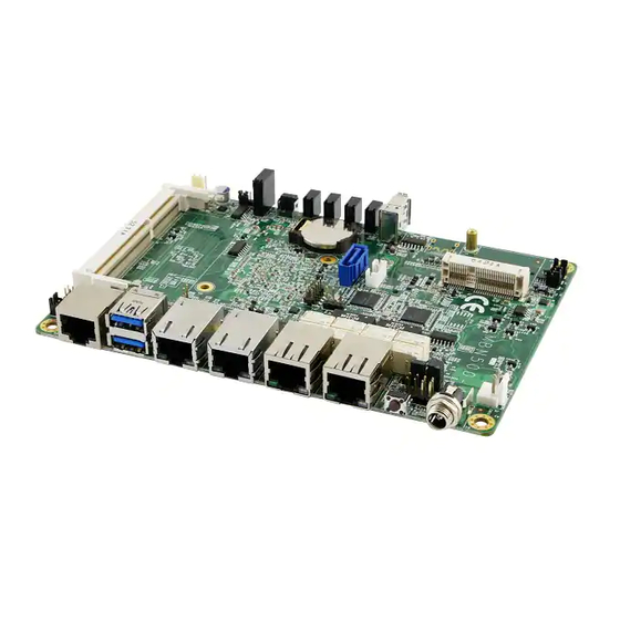
- Page 15 CN1: SATA3.0 Port CN3:USB3.0 Port(x2) CN4: USB2.0 Port(x1) CN2: CFAST Connector J5: Mini PCI- E(x1) W/USB Connector CN6,CN7,CN8,CN9: Intel I211 LAN J3:SODIMM Socket CN5: MINI DP (only MBN500-4CG) LED1, LED2, LED3, LED4: LAN Port Link, Active LED MBN500 series User’s Manu...
- Page 15 CN1: SATA3.0 Port CN3:USB3.0 Port(x2) CN4: USB2.0 Port(x1) CN2: CFAST Connector J5: Mini PCI- E(x1) W/USB Connector CN6,CN7,CN8,CN9: Intel I211 LAN J3:SODIMM Socket CN5: MINI DP (only MBN500-4CG) LED1, LED2, LED3, LED4: LAN Port Link, Active LED MBN500 series User’s Manu...
-
Page 16: Bios Setup
BIOS Setup BIOS Setup This chapter describes the different settings available in the BIOS that comes with the board. MBN500 Series User’s Manual... -
Page 16: Bios Setup
BIOS Setup BIOS Setup This chapter describes the different settings available in the BIOS that comes with the board. MBN500 Series User’s Manual... -
Page 17: Bios Introduction
<PgUp> and <PgDn> keys to change entries, <F1> for help and <Esc> to quit. When you enter the Setup utility, the Main Menu screen will appear on the screen. The Main Menu allows you to select from various setup functions and exit choices. MBN500 series User’s Manu... -
Page 17: Bios Introduction
<PgUp> and <PgDn> keys to change entries, <F1> for help and <Esc> to quit. When you enter the Setup utility, the Main Menu screen will appear on the screen. The Main Menu allows you to select from various setup functions and exit choices. MBN500 series User’s Manu... -
Page 18: System Date
Access Level Administrator F2: Previous Values F3: Optimized Default F4: Save ESC: Exit System Date Set the Date. Use Tab to switch between Data elements. System Time Set the Time. Use Tab to switch between Time elements. MBN500 Series User’s Manual... -
Page 18: System Date
Access Level Administrator F2: Previous Values F3: Optimized Default F4: Save ESC: Exit System Date Set the Date. Use Tab to switch between Data elements. System Time Set the Time. Use Tab to switch between Time elements. MBN500 Series User’s Manual... -
Page 19: Advanced Settings
Enables or Disables System ability to Hibernate (OS/S4 Sleep State). This option may be not effective with some OS. ACPI Sleep State Select ACPI sleep state the system will enter, when the SUSPEND button is pressed. MBN500 series User’s Manu... -
Page 19: Advanced Settings
Enables or Disables System ability to Hibernate (OS/S4 Sleep State). This option may be not effective with some OS. ACPI Sleep State Select ACPI sleep state the system will enter, when the SUSPEND button is pressed. MBN500 series User’s Manu... -
Page 20: Cpu Configuration
NX Mode Enable/disable No-execute page protection function. SVM Mode Enable/disable CPU Virtualization. CPB Mode Enable/disable CPB. Core Leveling Mode Change the number of cores in the system. Node 0 Information View memory information related to Node 0. MBN500 Series User’s Manual... -
Page 21: Ide Configuration
Advanced Main Chipset Boot Security Save & Exit ACPI Shutdown Temperature [Disabled] → ← Select Screen ↑↓ Select Item Enter: Select Change Field F1: General Help F2: Previous Values F3: Optimized Default F4: Save ESC: Exit MBN500 series User’s Manu... -
Page 21: Ide Configuration
Advanced Main Chipset Boot Security Save & Exit ACPI Shutdown Temperature [Disabled] → ← Select Screen ↑↓ Select Item Enter: Select Change Field F1: General Help F2: Previous Values F3: Optimized Default F4: Save ESC: Exit MBN500 series User’s Manu... -
Page 22: Usb Configuration
EHCI ownership change should be claimed by EHCI driver. USB MASS Storage Driver Support Enable/Disable USB Mass Storage Driver Support. USB Transfer time-out The time-out value for Control, Bulk, and Interrupt transfers. Device reset time-out USB mass storage device start unit command time-out. MBN500 Series User’s Manual... -
Page 23: Serial Port 0 Configuration
Power-on after power failure [power on] F2: Previous Values F3: Optimized Default F4: Save ESC: Exit Serial Port 0 Configuration Set parameters of Serial Port 0 (COMA) Serial Port 1 Configuration Set parameters of Serial Port 1 (COMB) MBN500 series User’s Manu... -
Page 24: Smart Fan Function
Enter: Select Windows Emergency Management Services (EMS) Change Field Console Redirection [Disabled] F1: General Help ► Console Redirection Settings F2: Previous Values F3: Optimized Default F4: Save ESC: Exit Console Redirection Console Redirection Enable or Disable MBN500 Series User’s Manual... -
Page 25: Chipset Settings
OnChip SATA Type [AHCI] → ← Select Screen OnChip IDE mode [Legacy mode] ↑↓ Select Item SATA IDE Combined Mode [Enabled] Enter: Select Change Field F1: General Help F2: Previous Values F3: Optimized Default F4: Save ESC: Exit MBN500 series User’s Manu... -
Page 25: Chipset Settings
OnChip SATA Type [AHCI] → ← Select Screen OnChip IDE mode [Legacy mode] ↑↓ Select Item SATA IDE Combined Mode [Enabled] Enter: Select Change Field F1: General Help F2: Previous Values F3: Optimized Default F4: Save ESC: Exit MBN500 series User’s Manu... -
Page 26: Boot Settings
► CSM16 parameters CSM parameters Setup Prompt Timeout Number of seconds to wait for setup activation key. 65535(0xFFFF) means indefinite waiting. Bootup NumLock State Select the keyboard NumLock state. Quiet Boot Enables or Disables Quiet Boot option. MBN500 Series User’s Manual... -
Page 27: Fast Boot
UPON REQUEST – GA20 can be disabled using BIOS services. ALWAYS – do not allow disabling GA20 ; this option is useful when any RT code is executed above 1MB Option ROM Messages Set display mode for Option ROM MBN500 series User’s Manu... -
Page 27: Fast Boot
UPON REQUEST – GA20 can be disabled using BIOS services. ALWAYS – do not allow disabling GA20 ; this option is useful when any RT code is executed above 1MB Option ROM Messages Set display mode for Option ROM MBN500 series User’s Manu... -
Page 28: Csm Parameters
Controls the execution of UEFI and Legacy Storage OpROM. Launch Video OpROM policy Controls the execution of UEFI and Legacy Video OpROM. Other PCI device ROM priority For PCI devices other than Network, Mass storage or Video defines which OpROM to launch. MBN500 Series User’s Manual... -
Page 29: Security Settings
Maximum length ↑↓ Select Item Enter: Select Change Field Administrator Password F1: General Help User Password F2: Previous Values F3: Optimized Default F4: Save ESC: Exit Administrator Password Set Setup Administrator Password. User Password Set User Password. MBN500 series User’s Manu... -
Page 30: Save Changes And Exit
Discard Changes done so far to any of the setup options. Restore Defaults Restore/Load Defaults values for all the setup options. Save as User Defaults Save the changes done so far as User Defaults. Restore User Defaults Restore the User Defaults to all the setup options. MBN500 Series User’s Manual... -
Page 31: Drivers Installation
The contents of this section include the following: Chipset Drivers Installation ..............41 LAN Drivers Installation ..............46 IMPORTANT NOTE: After installing your Windows operating system, you must install first the Intel Chipset Software Installation Utility before proceeding with the drivers installation. MBN500 series User’s Manual... -
Page 32: Chipset Software Installation Utility
Drivers Installation Chipset Software Installation Utility 1. In the Drvier folder, execute the CDGulde file. Click AMD, then AMD Steppe Eagle Drivers. 2. Click AMD Steppe Eagle Graphics Drivers. MBN500 Series User’s Manual... -
Page 32: Chipset Software Installation Utility
Drivers Installation Chipset Software Installation Utility 1. In the Drvier folder, execute the CDGulde file. Click AMD, then AMD Steppe Eagle Drivers. 2. Click AMD Steppe Eagle Graphics Drivers. MBN500 Series User’s Manual... - Page 33 Drivers Installation MBN500 series User’s Manu...
- Page 33 Drivers Installation MBN500 series User’s Manu...
- Page 34 Drivers Installation 3. Select the language you would like to be displayed and click Next. MBN500 Series User’s Manual...
- Page 34 Drivers Installation 3. Select the language you would like to be displayed and click Next. MBN500 Series User’s Manual...
- Page 35 Drivers Installation 4. Select Express and the installation location and click Next. MBN500 series User’s Manu...
- Page 35 Drivers Installation 4. Select Express and the installation location and click Next. MBN500 series User’s Manu...
- Page 36 Drivers Installation 5. Click Accept to accept the End User License Agreement. 6. To reboot the system, click Yes. MBN500 Series User’s Manual...
- Page 36 Drivers Installation 5. Click Accept to accept the End User License Agreement. 6. To reboot the system, click Yes. MBN500 Series User’s Manual...
-
Page 37: Lan Drivers Installation
Drivers Installation LAN Drivers Installation 1. In the Drvier folder, execute the CDGulde file. 2. Click LAN Card and then Intel LAN Controller Drivers. 3.Click Intel(R) I21x Gigabit Network Drivers MBN500 series User’s Manu... -
Page 37: Lan Drivers Installation
Drivers Installation LAN Drivers Installation 1. In the Drvier folder, execute the CDGulde file. 2. Click LAN Card and then Intel LAN Controller Drivers. 3.Click Intel(R) I21x Gigabit Network Drivers MBN500 series User’s Manu... - Page 38 4. Click the checkbox for Drivers in the Setup Options screen to select it and click Next to continue. 5. When the Ready to Install the Program screen appears, click Install to continue. 6. When InstallShield Wizard is complete, click Finish. MBN500 Series User’s Manual...
- Page 38 4. Click the checkbox for Drivers in the Setup Options screen to select it and click Next to continue. 5. When the Ready to Install the Program screen appears, click Install to continue. 6. When InstallShield Wizard is complete, click Finish. MBN500 Series User’s Manual...
-
Page 39: Appendix
00A2h-00BFh Motherboard resources 00C0h-000Dh Direct memory access controller 00F0h-00FFh Numeric data processor 02F8h-02FFh Communications Port (COM2) 03B0h-03BBh PCI Express standard Root Port 03B8h-03DFh PCI bus 03F8h-03FFh Communications Port (COM1) 0CD8h-0CDFh Motherboard resources F000h-F00Fh AMD SATA Controller MBN500 Series User’s Manual... -
Page 40: Interrupt Request Lines (Irq)
Standard Enhanced PCI to USB Host Controller IRQ 18 Standard Enhanced PCI to USB Host Controller IRQ 19 AMD SATA Controller IRQ81 Microsoft ACPI-Compliant System IRQ82 Microsoft ACPI-Compliant System IRQ83 Microsoft ACPI-Compliant System IRQ84 Microsoft ACPI-Compliant System MBN500 Series User’s Manual... -
Page 41: Watchdog Timer Configuration
#define NCT5523D_DATA_PORT (NCT5523D_BASE+1) //--------------------------------------------------------------------------- #define NCT5523D_REG_LD 0x07 //--------------------------------------------------------------------------- #define NCT5523D_UNLOCK 0x87 #define NCT5523D_LOCK 0xAA //--------------------------------------------------------------------------- unsigned int Init_NCT5523D(void); void Set_NCT5523D_LD( unsigned char); void Set_NCT5523D_Reg( unsigned char, unsigned char); unsigned char Get_NCT5523D_Reg( unsigned char); //--------------------------------------------------------------------------- #endif //__NCT5523D_H MBN500 Series User’s Manual... -
Page 41: Watchdog Timer Configuration
#define NCT5523D_DATA_PORT (NCT5523D_BASE+1) //--------------------------------------------------------------------------- #define NCT5523D_REG_LD 0x07 //--------------------------------------------------------------------------- #define NCT5523D_UNLOCK 0x87 #define NCT5523D_LOCK 0xAA //--------------------------------------------------------------------------- unsigned int Init_NCT5523D(void); void Set_NCT5523D_LD( unsigned char); void Set_NCT5523D_Reg( unsigned char, unsigned char); unsigned char Get_NCT5523D_Reg( unsigned char); //--------------------------------------------------------------------------- #endif //__NCT5523D_H MBN500 Series User’s Manual... - Page 42 Nuvoton NCT5523D, program abort.\n"); return(1); WDTInitial(); WDTEnable(10); WDTDisable(); return 0; //--------------------------------------------------------------------------- void WDTInitial(void) unsigned char bBuf; Set_NCT5523D_LD(0x08); //switch to logic device 8 bBuf = Get_NCT5523D_Reg(0x30); bBuf &= (~0x01); Set_NCT5523D_Reg(0x30, bBuf); //Enable WDTO //--------------------------------------------------------------------------- MBN500 Series User’s Manual...
- Page 42 Nuvoton NCT5523D, program abort.\n"); return(1); WDTInitial(); WDTEnable(10); WDTDisable(); return 0; //--------------------------------------------------------------------------- void WDTInitial(void) unsigned char bBuf; Set_NCT5523D_LD(0x08); //switch to logic device 8 bBuf = Get_NCT5523D_Reg(0x30); bBuf &= (~0x01); Set_NCT5523D_Reg(0x30, bBuf); //Enable WDTO //--------------------------------------------------------------------------- MBN500 Series User’s Manual...
- Page 43 Set_NCT5523D_Reg(0x30, 0x01); //enable timer bBuf = Get_NCT5523D_Reg(0xF0); bBuf &= (~0x08); Set_NCT5523D_Reg(0xF0, bBuf); //count mode is second Set_NCT5523D_Reg(0xF1, NewInterval); //set timer //--------------------------------------------------------------------------- void WDTDisable(void) Set_NCT5523D_LD(0x08); //switch to logic device 8 Set_NCT5523D_Reg(0xF1, 0x00); //clear watchdog timer Set_NCT5523D_Reg(0x30, 0x00); //watchdog disabled //--------------------------------------------------------------------------- MBN500 Series User’s Manual...
- Page 43 Set_NCT5523D_Reg(0x30, 0x01); //enable timer bBuf = Get_NCT5523D_Reg(0xF0); bBuf &= (~0x08); Set_NCT5523D_Reg(0xF0, bBuf); //count mode is second Set_NCT5523D_Reg(0xF1, NewInterval); //set timer //--------------------------------------------------------------------------- void WDTDisable(void) Set_NCT5523D_LD(0x08); //switch to logic device 8 Set_NCT5523D_Reg(0xF1, 0x00); //clear watchdog timer Set_NCT5523D_Reg(0x30, 0x00); //watchdog disabled //--------------------------------------------------------------------------- MBN500 Series User’s Manual...
Need help?
Do you have a question about the MBN500 and is the answer not in the manual?
Questions and answers