
Related Manuals for IBASE Technology MBN800-8L


Summary of Contents for IBASE Technology MBN800-8L
- Page 1 MBN800-8L MBN800-6L Networking Motherboards ® with Intel PCH C236/H110 User’s Manual Version 1.0a (Nov. 2017)
- Page 2 No part of this publication may be reproduced, copied, stored in a retrieval system, translated into any language or transmitted in any form or by any means, electronic, mechanical, photocopying, or otherwise, without the prior written consent of IBASE Technology, Inc. (hereinafter referred to as “IBASE”).
-
Page 3: Compliance
Compliance This product has passed CE tests for environmental specifications and limits. This product is in accordance with the directives of the Union European (EU). If users modify and/or install other devices in this equipment, the CE conformity declaration may no longer apply. This product has been tested and found to comply with the limits for a Class A device, pursuant to Part 15 of the FCC Rules. -
Page 4: Important Safety Information
Important Safety Information Carefully read the precautions before using the device. Environmental conditions: • Lay the device horizontally on a stable and solid surface in case the device may fall, causing serious damage. • Slots and openings on the chassis are for ventilation. Do not block or cover these openings. -
Page 5: Caution
CAUTION Danger of explosion if internal lithium-ion battery is replaced by an incorrect type. Replace only with the same or equivalent type recommended by the manufacturer. Dispose of used batteries according to the manufacturer’s instructions. Under no circumstances should the Lithium battery cell be shorted; otherwise the battery cell may heat up or cause potential burn hazards. -
Page 6: Table Of Contents
Table of Contents Compliance....................iii Important Safety Information ............... iv WARNING ...................... iv CAUTION ......................v Warranty Policy ....................v Technical Support & Services ..............v Chapter 1 General Information ..............1 Introduction ..................... 2 Features ....................3 Packing List .................... 3 Optional Accessories ................ - Page 7 2.5.7 ATX Power Connector (J2, J14) ........... 24 2.5.8 External VGA Port (J3) ............25 Chapter 3 BIOS Setup ................26 Introduction ................... 27 BIOS Setup ................... 27 Main Settings ..................28 Advanced Settings ................29 3.4.1 CPU Configuration ..............29 3.4.2 Trusted Computing ..............
-
Page 8: Chapter 1 General Information
Chapter 1 General Information The information provided in this chapter includes: • Features • Packing List • Optional Accessories • Specifications • Overview • Dimensions... -
Page 9: Introduction
MBN800 series are specifically designed for the network security and management market. There are plenty of applications adopting network security or network management as listed below. MBN800 series include the following models: • ® MBN800-8L (with Intel PCH C236) • ® MBN800-6L... -
Page 10: Features
DDR4 DIMM 2133 MHz (ECC supported per CPU SKUs) • Up to 8 GbE LAN ports with 2 advanced LAN Bypass pairs • Optional IPMI 2.0 module to output through VGA port for MBN800-8L • CF slot and PCIe (x8) expansion slot(s) •... -
Page 11: Specifications
1.5 Specifications Motherboard MBN800-8L MBN800-6L • Windows 10 (64-bit) Operating • System Linux Ubuntu 16.04.3 Gen. Core™ Gen. Core™ i7/i5/i3 ® ® ® Intel Xeon Intel i7/i5/i3 processor LGA1151 processor LGA1151 ® ® Chipset Intel C236 PCH Intel H110 PCH... -
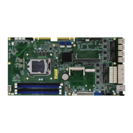
Page 12: Overview
General Information 1.6 Overview MBN800-8L MBN800-6L MBN800 Series User Manual... -
Page 13: Dimensions
1.7 Dimensions Unit: mm MBN800 Series User Manual... -
Page 14: Chapter 2 Hardware Configuration
Chapter 2 Hardware Configuration The information provided in this chapter includes: • Essential installations • Information and locations of connectors... -
Page 15: Essential Installations Before You Begin
2.1 Essential Installations For installation or replacement of CPU, memory modules, CF card, IPMI card & mini-PCIe card (IPMI & mini-PCIe slots are both available for MBN800-8L). 2.1.1 CPU Installation / Replacement Follow the instructions below to install or replace the CPU if necessary. -
Page 16: Memory Installation / Replacement
Hardware Configuration 2.1.2 Memory Installation / Replacement If you need to install or replace a memory module, follow the instructions below for installation after you disassemble the device cover. 1. Press the ejector tab of the memory slot down and outwards with your fingertips. -
Page 17: Cf Card & Ipmi Module Installation / Replacement
If you need to install a CF card or an IPMI module, remove the device cover firstly and then follow the instructions below. Note: 1. IPMI slot is available for MBN800-8L only. 2. IPMI module is optional for purchase. IPMI module: 1. -
Page 18: Setting The Jumpers
Hardware Configuration 2.2 Setting the Jumpers Set up and configure your MBN800 series by using jumpers for various settings and features according to your needs and applications. Contact your supplier if you have doubts about the best configuration for your use. 2.2.1 How to Set Jumpers Jumpers are short-length conductors consisting of several metal pins with a... -
Page 19: Jumper & Connector Locations On Motherboard
2.3 Jumper & Connector Locations on Motherboard Motherboard: MBN800-8L MBN800 Series User Manual... - Page 20 Hardware Configuration Motherboard: MBN800-6L MBN800 Series User Manual...
-
Page 21: Jumpers Quick Reference
2.4 Jumpers Quick Reference Function Connector Name Page ME Register Clearance JBAT3 CMOS Data Clearance JBAT4 Factory Use Only JBMC1, JBMC2 2.4.1 ME Register Clearance (JBAT3) Function Pin closed Illustration Normal (default) Clear ME Register MBN800 Series User Manual... -
Page 22: Cmos Data Clearance (Jbat4)
Hardware Configuration 2.4.2 CMOS Data Clearance (JBAT4) Function Pin closed Illustration Normal (default) Clear CMOS MBN800 Series User Manual... -
Page 23: Connectors Quick Reference
External VGA Port IPMI Connector* M.2 M2280 Slot* Mini-PCIe Slot* USB 3.0 Port DDR4 Slot MBN800-8L: J4, J5, J6, J7 MBN800-6L: J5, J7 LAN Port MBN800-8L: U61 (quadruple), CN7, CN8, CN9, CN10 (single) MBN800-6L: U61 (quadruple), CN7, CN8 (single) CF Card Slot SATA 3.0 Port... -
Page 24: System Function Connector (Jp3)
Hardware Configuration 2.5.1 System Function Connector (JP3) Assigment Assigment VCC5 SPEAKER Ground Ground VCC5 5VDUAL BYPASS8_LED- 5VDUAL BYPASS9_LED- Ground ATXPWR_BTN# Ground FRST_OUT VCC3_3 -HDD_LED JP3 is utilized for system indicators to provide light indication of the computer activities and switches to change the computer status. It provides interfaces for the following functions. - Page 25 • Power LED (Pins 1, 3 and 5) This connector connects to a system power LED on control panel. This LED will light when the system turns on. • Speaker (Pin 2, 4, 6 and 8) Connecting the 4 pins to a system speaker connector enables the speaker function.
-
Page 26: Digital I/O Port (Jp4)
Hardware Configuration 2.5.2 Digital I/O Port (JP4) Assigment Assigment Ground 5VDUAL INT0_SIOGP22 INT0_SIOGP25 INT0_SIOGP23 INT0_SIOGP26 INT0_SIOGP24 INT0_SIOGP27 MBN800 Series User Manual... -
Page 27: External Sata Power (Cn2, Cn4)
2.5.3 External SATA Power (CN2, CN4) Assigment Assigment VCC5 Ground Ground VCC12 MBN800 Series User Manual... -
Page 28: Lcm Port (Cn5)
Hardware Configuration 2.5.4 LCM Port (CN5) Assigment Assigment LCM_RD1 VCC5 LCM_TD1 Ground MBN800 Series User Manual... -
Page 29: Fan Connector (Fan_Cpu, Fan1, Fan2, Fan3, Fan4)
2.5.5 Fan Connector (FAN_CPU, FAN1, FAN2, FAN3, FAN4) CPU_FAN FAN1 FAN2 FAN3 FAN4 CPU_FAN, FAN1, FAN2, FAN3: Assigment Assigment Ground FAN_TACH VCC12 FAN_PWM FAN4: Assigment Assigment Ground FAN_TACH VCC12 MBN800 Series User Manual... -
Page 30: System Power Switch (J1)
Hardware Configuration 2.5.6 System Power Switch (J1) Assigment Assigment ATX_PSON#_EN Ground MBN800 Series User Manual... -
Page 31: Atx Power Connector (J2, J14)
2.5.7 ATX Power Connector (J2, J14) J14: J14: Assigment Assigment VCC3_3 VCC3_3 VCC3_3 -12V Ground Ground VCC5 ATX_PSON# Ground Ground Ground VCC5 Ground Ground PW_OK 5VSB VCC5 VCC12 VCC5 VCC12 VCC5 VCC3_3 Ground MBN800 Series User Manual... -
Page 32: External Vga Port (J3)
Hardware Configuration Assigment Assigment Ground Ground Ground Ground 2.5.8 External VGA Port (J3) Assigment Assigment CRT_R CRT_G Ground CRT_B CRT_DDC_DATA Ground CRT_HSYNC Ground CRT_VSYNC Ground CRT_DDC_CLK Ground MBN800 Series User Manual... -
Page 33: Chapter 3 Bios Setup
Chapter 3 BIOS Setup This chapter the different settings available in the AMI describes BIOS that comes with the board. The topics covered in this chapter are as follows: • Main Settings • Advanced Settings • Chipset Settings • Security Settings •... -
Page 34: Introduction
BIOS Setup 3.1 Introduction The BIOS (Basic Input/Output System) installed in the ROM of your computer system supports Intel® processors. The BIOS provides critical low-level support for standard devices such as disk drives, serial ports and parallel ports. It also provides password protection as well as special support for detailed fine-tuning of the chipset controlling the entire system. -
Page 35: Main Settings
3.3 Main Settings BIOS Setting Description System Date Sets the date. Use the <Tab> key to switch between the data elements. System Time Set the time. Use the <Tab> key to switch between the data elements. MBN800 Series User Manual... -
Page 36: Advanced Settings
BIOS Setup 3.4 Advanced Settings This section allows you to configure, improve your system and allows you to set up some system features according to your preference. 3.4.1 CPU Configuration BIOS Setting Description Intel(R) SpeedStep (tm) Enables / Disables the function to allow more than two frequency ranges to be supported. -
Page 37: Trusted Computing
3.4.2 Trusted Computing BIOS Setting Description Security Device Support Enables / Disables TPM support. O.S. will not show TPM. Reset of platform is required. Pending operation Schedule an operation for the security device. Note: Your computer will reboot during restart in order to change the state of security device. -
Page 38: Sata Configuration
BIOS Setup 3.4.3 SATA Configuration BIOS Setting Description SATA Controller(s) Enables / Disables SATA device. SATA Mode Selection Selects AHCI / Intel RST Premium Mode. SATA Controller Speed Selects the SATA controller speed as Default / Gen1 / Gen2 / Gen3. Serial ATA Port 0~4 Enables / Disables Serial Port 0 ~ 5. -
Page 39: Nct5523D Super Io Configuration
3.4.5 NCT5523D Super IO Configuration BIOS Setting Description Serial Port Configuration Sets Parameters of Serial Ports. You can enable / disable the serial port and select an optimal settings for the Super IO device. Restore AC Power Loss Chooses an AC power state to apply after a power failure. - Page 40 BIOS Setup 3.4.5.1. Serial Port 1 Configuration BIOS Setting Description Change Settings Selects an optimal settings for the Super I/O device. Options: • Auto • IO=3F8h ; IRQ=4 • IO=3F8h ; IRQ=3, 4, 5, 6, 7, 9. 10, 11, 12 •...
- Page 41 3.4.5.2. Serial Port 2 Configuration BIOS Setting Description Change Settings Selects an optimal settings for the Super I/O device. Options: • Auto • IO=2F8h ; IRQ=3 • IO=3F8h ; IRQ=3, 4, 5, 6, 7, 9. 10, 11, 12 • IO=2F8h ; IRQ=3, 4, 5, 6, 7, 9. 10, 11, 12 •...
-
Page 42: Hardware Monitor
BIOS Setup 3.4.6 Hardware Monitor BIOS Setting Description Smart Fan Control Sets up or disable the fan control for start-up temperature. Options: Disabled, 40°C, 45°C, 50°C, 55°C, 60°C Shutdown Temperature This field enables or disables the Shutdown Temperature Options: Disabled (default),. 70°C, 75°C, 80°C, 85°C, 90°C, 95°C Temperatures / Voltages These fields are the parameters of the... -
Page 43: Lan Bypass Configuration
3.4.7 LAN Bypass Configuration BIOS Setting Description Bypass Quick Normal: All LAN ports are in a normal state. WDT Setting monitor system hang and initiates a reboot. Bypass: All LAN ports in Bypass during power-off or WDT initiates bypass. Options: Bypass, Normal, Firewall, Custom Define 3.4.8 Console Port Configuration BIOS Setting... - Page 44 BIOS Setup BIOS Setting Description Therminal Type Sets the terminal type as VT100, VT100+, VT-UTF8, or ANSI. Bits per second Selects serial port transmission speed. The speed msut be matched on the other side. Long or noisy lines may require lower speeds. Options: 9600 19200, 38400, 57600, 115200 Data Bits Options: 7, 8...
-
Page 45: Usb Configuration
3.4.9 USB Configuration BIOS Setting Description Legacy USB Support Enables / Disables Legacy USB support. • Auto disables legacy support if there is no USB device connected. • Disable keeps USB devices available only for EFI applications. XHCI Hand-pff This is a workaround for OSes without XHCI hand-off support. -
Page 46: Security Settings
BIOS Setup 3.5 Security Settings BIOS Setting Description Administrator Password Sets an administrator password for the setup utility. User Password Sets a user password. MBN800 Series User Manual... -
Page 47: Boot Settings
3.6 Boot Settings BIOS Setting Description Setup Prompt Timeout Number of seconds to wait for setup activation key. 65535 (0xFFFF) means indefinite waiting. Bootup NumLock State Selects the keyboard NumLock state. Quiet Boot Enables / Disables Quiet Boot option. Network Controls the execution of UEFI and Legacy PXE OpROM. -
Page 48: Save & Exit Settings
BIOS Setup 3.7 Save & Exit Settings BIOS Setting Description Save Changes and Reset Resets the system after saving the changes. Discard Changes and Resets system setup without saving any Reset changes. Restore Defaults Restores / Loads defaults values for all the setup options. -
Page 49: Server Management
3.8 Server Management BIOS Setting Description BMC Support Enables / Disables interfaces to communicate with BMC. Wait for BMC Wait for BMC response for specificed time out. In PILOTII, BMC starts at the same time when BIOS starts during AC power On. It takes around 30 seconds to initialize Host to BMC. - Page 50 BIOS Setup 3.8.1 System Event Log BIOS Setting Description SEL Components Change this to enable or disable all features of system event logging during boot. Erase SEL Chooses options for erasing SEL. Options: No, Yes (on next reset),Yes (on every reset) When SEL is Full Chooses options for reactions to a full SEL.
-
Page 51: Bmc Network Configuration
3.8.2 BMC Network Configuration BIOS Setting Description Configuration Address Configures LAN channel parameters statically or Source dynamically (by BIOS or BMC). Options: Unspecified, Static, DynamicBmcDhcp, DynamicBmcNonDhcp BIOS Setting Description IPV6 Support Enables / Disables LAN1 IPV6 support. Configuration Address Configures LAN channel parameters statically or Source dynamically (by BIOS or BMC). -
Page 52: Appendix
Appendix This section provides the mapping addresses of peripheral devices and the sample code of watchdog timer configuration. • I/O Port Address Map • Interrupt Request Lines (IRQ) • Watchdog Timer Configuration... -
Page 53: I/O Port Address Map
A. I/O Port Address Map Each peripheral device in the system is assigned a set of I/O port addresses which also becomes the identity of the device. The following table lists the I/O port addresses used. MBN800-8L: Address Device Description 0x00000A00-0x00000A0F... - Page 54 Appendix Address Device Description 0x0000F090-0x0000F097 Standard SATA AHCI Controller 0x0000F080-0x0000F083 Standard SATA AHCI Controller 0x0000F040-0x0000F05F Standard SATA AHCI Controller 0x000003F8-0x000003FF Communications Port (COM1) 0x000002F8-0x000002FF Communications Port (COM2) 0x00007000-0x00007FFF Intel(R) 100 Series/C230 Series Chipset Family PCI Express Root Port #3 - A112 0x0000C000-0x0000CFFF Intel(R) 100 Series/C230 Series Chipset Family PCI Express Root Port #8 - A117...
- Page 55 Address Device Description 0x0000F000-0x0000F03F Intel(R) HD Graphics 630 0x000003B0-0x000003BB Intel(R) HD Graphics 630 0x000003C0-0x000003DF Intel(R) HD Graphics 630 0x0000FF00-0x0000FFFE Motherboard resources 0x0000E000-0x0000EFFF Intel(R) 100 Series/C230 Series Chipset Family PCI Express Root Port #10 - A119 0x0000F060-0x0000F07F Intel(R) 100 Series/C230 Series Chipset Family SMBus - A123 0x0000B000-0x0000BFFF Intel(R) 100 Series/C230 Series Chipset...
- Page 56 Appendix Address Device Description 0x0000FFFF-0x0000FFFF Motherboard resources 0x0000FFFF-0x0000FFFF Motherboard resources 0x0000FFFF-0x0000FFFF Motherboard resources 0x00001800-0x000018FE Motherboard resources 0x0000164E-0x0000164F Motherboard resources 0x0000D000-0x0000DFFF Intel(R) 100 Series/C230 Series Chipset Family PCI Express Root Port #9 - A118 0x00000800-0x0000087F Motherboard resources 0x0000A000-0x0000AFFF Intel(R) 100 Series/C230 Series Chipset Family PCI Express Root Port #6 - A115 0x000000F0-0x000000F0 Numeric data processor...
- Page 57 Address Device Description 0x0000B000-0x0000BFFF Intel(R) 100 Series/C230 Series Chipset Family PCI Express Root Port #7 - A116 0x00000020-0x00000021 Programmable interrupt controller 0x00000024-0x00000025 Programmable interrupt controller 0x00000028-0x00000029 Programmable interrupt controller 0x0000002C-0x0000002D Programmable interrupt controller 0x00000030-0x00000031 Programmable interrupt controller 0x00000034-0x00000035 Programmable interrupt controller 0x00000038-0x00000039 Programmable interrupt controller 0x0000003C-0x0000003D...
-
Page 58: Interrupt Request Lines (Irq)
Appendix B. Interrupt Request Lines (IRQ) Peripheral devices use interrupt request lines to notify CPU for the service required. The following table shows the IRQ used by the devices on board. MBN800-8L: Level Function IRQ 0 System timer IRQ 3... - Page 59 Level Function IRQ 4294967271 ~ Intel(R) I210 Gigabit Network Connection #2 IRQ 4294967276 IRQ 4294967277 ~ Intel(R) I210 Gigabit Network Connection IRQ 4294967282 IRQ 4294967283 Standard SATA AHCI Controller IRQ 4294967284 Intel(R) 100 Series/C230 Series Chipset Family PCI Express Root Port #10 - A119 IRQ 4294967285 Intel(R) 100 Series/C230 Series Chipset Family PCI Express Root Port #9 - A118...
- Page 60 Appendix MBN800-6L: Address Device Description IRQ 0 System timer IRQ 3 Communications Port (COM2) IRQ 4 Communications Port (COM1) IRQ 8 System CMOS/real time clock IRQ 9 Intel(R) Xeon(R) E3 - 1200/1500 v5/6th Gen Intel(R) Core(TM) Gaussian Mixture Model - 1911 IRQ 9 Intel(R) 100 Series/C230 Series Chipset...
- Page 61 Address Device Description IRQ 4294967289 Intel(R) 100 Series/C230 Series Chipset Family PCI Express Root Port #9 - A118 IRQ 4294967290 Intel(R) 100 Series/C230 Series Chipset Family PCI Express Root Port #8 - A117 IRQ 4294967291 Intel(R) 100 Series/C230 Series Chipset Family PCI Express Root Port #7 - A116 IRQ 4294967292 Intel(R) 100 Series/C230 Series Chipset...
-
Page 62: Digital I/O Sample Code
Appendix C. Digital I/O Sample Code 1. DIO Sample Code: The file NCT5523D.H //--------------------------------------------------------------------------- // THIS CODE AND INFORMATION IS PROVIDED "AS IS" WITHOUT WARRANTY OF ANY // KIND, EITHER EXPRESSED OR IMPLIED, INCLUDING BUT NOT LIMITED TO THE // IMPLIED WARRANTIES OF MERCHANTABILITY AND/OR FITNESS FOR A PARTICULAR // PURPOSE. - Page 63 2. DIO Sample Code: The file MAIN.CPP //--------------------------------------------------------------------------- // THIS CODE AND INFORMATION IS PROVIDED "AS IS" WITHOUT WARRANTY OF ANY // KIND, EITHER EXPRESSED OR IMPLIED, INCLUDING BUT NOT LIMITED TO THE // IMPLIED WARRANTIES OF MERCHANTABILITY AND/OR FITNESS FOR A PARTICULAR // PURPOSE.
- Page 64 Appendix void Dio5Initial(void) unsigned char ucBuf; ucBuf = Get_NCT5523D_Reg(0x1C); ucBuf &= ~0x02; Set_NCT5523D_Reg(0x1C, ucBuf); Set_NCT5523D_LD(0x07); //switch to logic device 7 //enable the GP2 group ucBuf = Get_NCT5523D_Reg(0x30); ucBuf |= 0x04; Set_NCT5523D_Reg(0x30, ucBuf); //--------------------------------------------------------------------------- void Dio5SetOutput(unsigned char NewData) Set_NCT5523D_LD(0x07); //switch to logic device 7 Set_NCT5523D_Reg(0xE1, NewData);...
- Page 65 3. DIO Sample Code: The file NCT5523D.CPP //--------------------------------------------------------------------------- // THIS CODE AND INFORMATION IS PROVIDED "AS IS" WITHOUT WARRANTY OF ANY // KIND, EITHER EXPRESSED OR IMPLIED, INCLUDING BUT NOT LIMITED TO THE // IMPLIED WARRANTIES OF MERCHANTABILITY AND/OR FITNESS FOR A PARTICULAR // PURPOSE.
- Page 66 Appendix void Set_NCT5523D_LD( unsigned char LD) Unlock_NCT5523D(); outportb(NCT5523D_INDEX_PORT, NCT5523D_REG_LD); outportb(NCT5523D_DATA_PORT, LD); Lock_NCT5523D(); //--------------------------------------------------------------------------- void Set_NCT5523D_Reg( unsigned char REG, unsigned char DATA) Unlock_NCT5523D(); outportb(NCT5523D_INDEX_PORT, REG); outportb(NCT5523D_DATA_PORT, DATA); Lock_NCT5523D(); //--------------------------------------------------------------------------- unsigned char Get_NCT5523D_Reg(unsigned char REG) unsigned char Result; Unlock_NCT5523D(); outportb(NCT5523D_INDEX_PORT, REG); Result = inportb(NCT5523D_DATA_PORT); Lock_NCT5523D();...
-
Page 67: Watchdog Timer Configuration
D. Watchdog Timer Configuration The Watchdog Timer (WDT) is used to generate a variety of output signals after a user programmable count. The WDT is suitable for the use in the prevention of system lock-up, such as when software becomes trapped in a deadlock. - Page 68 Appendix 2. WDT Sample Code: The file MAIN.CPP //--------------------------------------------------------------------------- // THIS CODE AND INFORMATION IS PROVIDED "AS IS" WITHOUT WARRANTY OF ANY // KIND, EITHER EXPRESSED OR IMPLIED, INCLUDING BUT NOT LIMITED TO THE // IMPLIED WARRANTIES OF MERCHANTABILITY AND/OR FITNESS FOR A PARTICULAR // PURPOSE.
- Page 69 void WDTEnable(unsigned char NewInterval) unsigned char bBuf; Set_NCT5523D_LD(0x08); //switch to logic device 8 Set_NCT5523D_Reg(0x30, 0x01); //enable timer bBuf = Get_NCT5523D_Reg(0xF0); bBuf &= (~0x08); Set_NCT5523D_Reg(0xF0, bBuf); //count mode is second Set_NCT5523D_Reg(0xF1, NewInterval); //set timer //--------------------------------------------------------------------------- void WDTDisable(void) Set_NCT5523D_LD(0x08); //switch to logic device 8 Set_NCT5523D_Reg(0xF1, 0x00);...
- Page 70 Appendix 3. WDT Sample Code: The file NCT5523D.CPP //--------------------------------------------------------------------------- // THIS CODE AND INFORMATION IS PROVIDED "AS IS" WITHOUT WARRANTY OF ANY // KIND, EITHER EXPRESSED OR IMPLIED, INCLUDING BUT NOT LIMITED TO THE // IMPLIED WARRANTIES OF MERCHANTABILITY AND/OR FITNESS FOR A PARTICULAR // PURPOSE.
- Page 71 void Lock_NCT5523D (void) outportb(NCT5523D_INDEX_PORT, NCT5523D_LOCK); //--------------------------------------------------------------------------- void Set_NCT5523D_LD( unsigned char LD) Unlock_NCT5523D(); outportb(NCT5523D_INDEX_PORT, NCT5523D_REG_LD); outportb(NCT5523D_DATA_PORT, LD); Lock_NCT5523D(); //--------------------------------------------------------------------------- void Set_NCT5523D_Reg( unsigned char REG, unsigned char DATA) Unlock_NCT5523D(); outportb(NCT5523D_INDEX_PORT, REG); outportb(NCT5523D_DATA_PORT, DATA); Lock_NCT5523D(); //--------------------------------------------------------------------------- unsigned char Get_NCT5523D_Reg(unsigned char REG) unsigned char Result; Unlock_NCT5523D();...
Need help?
Do you have a question about the MBN800-8L and is the answer not in the manual?
Questions and answers