
Related Manuals for IBASE Technology MB991


Summary of Contents for IBASE Technology MB991
- Page 1 MB991AF Core™ / ® ® Intel Xeon ® ® Pentium / Celeron Micro-ATX Motherboard User’s Manual Version 1.0 (Aug. 2018)
- Page 2 No part of this publication may be reproduced, copied, stored in a retrieval system, translated into any language or transmitted in any form or by any means, electronic, mechanical, photocopying, or otherwise, without the prior written consent of IBASE Technology, Inc. (hereinafter referred to as “IBASE”). Disclaimer IBASE reserves the right to make changes and improvements to the products described in this document without prior notice.
-
Page 3: Compliance
Compliance This is a class B product. In a domestic environment, this product may cause radio interference in which case users may be required to take adequate measures. This product has been tested and found to comply with the limits for a Class B device, pursuant to Part 15 of the FCC Rules. -
Page 4: Important Safety Information
Important Safety Information Carefully read the precautions before using the board. Environmental conditions: • Use this product in environments with ambient temperatures between 0˚C and 60˚C. • Do not leave this product in an environment where the storage temperature may be below -20° C or above 80° C. To prevent from damages, the product must be used in a controlled environment. -
Page 5: Warranty Policy
Warranty Policy • IBASE standard products: 24-month (2-year) warranty from the date of shipment. If the date of shipment cannot be ascertained, the product serial numbers can be used to determine the approximate shipping date. • -party parts: 12-month (1-year) warranty from delivery for the 3 -party parts that are not manufactured by IBASE, such as CPU, CPU cooler, memory, storage devices, power adapter, panel and touchscreen. -
Page 6: Table Of Contents
Table of Contents Compliance ..................iii Important Safety Information ............iv Warranty Policy ................v Technical Support & Services ............v Chapter 1 General Information ..........1 Introduction ..................2 Features ....................2 Packing List ..................3 Optional Accessories ................3 Specifications .................. - Page 7 2.5.7 LVDS Backlight Connector (J17) .........25 2.5.8 Front Panel Setting Connector (J21) ........26 2.5.9 ATX Power Connector (J24) ..........27 2.5.10 AT 12V Power Connector (ATX_12V_2X1) ......28 2.5.11 CPU Fan Power Connector (CPU_FAN1) ......29 2.5.12 System Fan Power Connector (SYS_FAN1, SYS_FAN2) ..29 Chapter 3 Drivers Installation ..........
- Page 8 Appendix ..................73 I/O Port Address Map ................ 74 Interrupt Request Lines (IRQ) ............77 Watchdog Timer Configuration ............79 On-Board Connector Types ............... 83 MB991AF User’s Manual viii...
-
Page 9: Chapter 1 General Information
Chapter 1 General Information The information provided in this chapter includes: • Features • Packing List • Specifications • Block Diagram • Board Overview • Board Dimensions... -
Page 10: Introduction
Introduction ® ® MB991AF is a Micro ATX motherboard based on the platform of Intel Xeon Gen. Core™ / Pentium ® ® / Celeron QC or DC processor. It offers high-definition visual experience and high performance on graphics processing. It can also be well utilized for designs of low power consumption in a board range of markets, including industrial control &... -
Page 11: Packing List
General Information Packing List Your MB991AF package should include the items listed below. If any of the items below is missing, contact the distributor or dealer from whom you purchased the product. • MB991AF Motherboard • I/O Shield • SATA Cable (SATA-3F) •... -
Page 12: Specifications
Specifications Product Name MB991AF-C236 MB991AF Form Factor Micro-ATX motherboard System • Windows 10 (64-bit) Operating • Linux Fedora (64-bit) & Ubuntu (64-bit) System Gen. Core™ i-Series. ® Windows 7 (64-bit) is only for Intel Gen. Core™ i7/i5/i3 / Pentium ® ®... - Page 13 General Information Product Name MB991AF-C236 MB991AF RoHS CE, FCC Class B, LVD Certification I/O Ports • 2 x HDMI 1.4 (4096 x 2160 at 24 Hz) Display • 1 x LVDS (1920 x 1200 at 60 Hz, 18-bit / 24-bit, dual channel) 2 x RJ45 GbE LAN •...
-
Page 14: Block Diagram
Block Diagram MB991AF User’s Manual... -
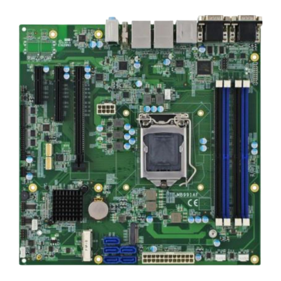
Page 15: Overview
General Information Overview Top View *The photos above are for reference only. Some minor components may differ. I/O View Name Name COM1 & COM2 Ports Audio Line-In (from top to bottom) COM3 & COM4 Ports Audio Line-Out (from top to bottom) USB 3.0 Ports Microphone-In LAN Ports... -
Page 16: Dimensions
Dimensions 243.84 237.49 165.1 33.02 10.16 35.52 31.05 29.85 28.38 MB991AF User’s Manual... -
Page 17: Chapter 2 Hardware Configuration
Chapter 2 Hardware Configuration This section provides information on jumper settings and connectors on the MB991AF in order to set up a workable system. On top of that, you will also need to install crucial pieces such as the CPU and the memory before using the product. The topics covered are: •... -
Page 18: Essential Installations Before You Begin
Installations 2.1.1 Installing the Memory The MB991AF board supports four DDR4 memory sockets for a maximum total memory of 64 GB. To install the modules, locate the memory slot on the board and perform the following steps: Press the ejector tab of the memory slot down and outwards with your fingertips. -
Page 19: Setting The Jumpers
Hardware Configuration Setting the Jumpers Set up and configure your MB991AF by using jumpers for various settings and features according to your needs and applications. Contact your supplier if you have doubts about the best configuration for your use. 2.2.1 How to Set Jumpers Jumpers are short-length conductors consisting of several metal pins with a non-conductive base mounted on the circuit board. -
Page 20: Jumper & Connector Locations On Mb991Af
Jumper & Connector Locations on MB991AF CN1 & CPU_FAN1 ATX_12V_2X1 ® Intel Gen. Core™ / ® Pentium ® Celeron QC or DC REMOVE ® Intel C236 / Battery Q170 CN10 CN11 SYS_FAN1 SYS_FAN2 CN12 CN13 Board diagram of MB991AF MB991AF User’s Manual... -
Page 21: Jumpers Quick Reference
Hardware Configuration Jumpers Quick Reference Function Jumper Name Page CMOS Data Clearance RTC Data Clearance LVDS Power Selection LVDS Backlight Power Selection PCIe (x16) Bifurcation Factory Use Only 2.4.1 CMOS Data Clearance (JP3) Function Pin closed Illustration Normal (default) Clear CMOS MB991AF User’s Manual... -
Page 22: Rtc Data Clearance (Jp4)
2.4.2 RTC Data Clearance (JP4) Function Pin closed Illustration Normal (default) Clear RTC MB991AF User’s Manual... -
Page 23: Lvds Power Selection (Jp5)
Hardware Configuration 2.4.3 LVDS Power Selection (JP5) Function Pin closed Illustration 3.3V (default) MB991AF User’s Manual... -
Page 24: Lvds Backlight Power Selection (Jp6)
2.4.4 LVDS Backlight Power Selection (JP6) Function Pin closed Illustration 3.3V Open (default) Close MB991AF User’s Manual... -
Page 25: Pcie (X16) Bifurcation (Jp8)
Hardware Configuration 2.4.5 PCIe (x16) Bifurcation (JP8) Function Pin closed Illustration Open (default) x4, x4 Close MB991AF User’s Manual... -
Page 26: Connectors Quick Reference
Connectors Quick Reference Function Connector Name Page COM1 & COM2 RS-232/422/485 Ports COM3 & COM4 RS-232 Ports Digital I/O Connector J7 (COM7 & COM8), COM7 ~ COM10 Ports J8 (COM9 & COM10) J9 (2 channel), LVDS Connector J15 (1 channel) USB 2.0 Ports J14, J16 LVDS Backlight Connector... -
Page 27: Com1 & Com2 Rs-232/422/485 Ports (Cn3)
Hardware Configuration 2.5.1 COM1 & COM2 RS-232/422/485 Ports (CN3) COM1 & COM2 ports are jumper-less and configurable in BIOS. Assigment Assigment DCD, Data carrier detect DSR, Data set ready RXD, Receive data RTS, Request to send TXD, Transmit data CTS, Clear to send DTR, Data terminal ready RI, Ring indicator Ground... -
Page 28: Com3 & Com4 Ports (Cn2)
2.5.2 COM3 & COM4 Ports (CN2) Assigment Assigment DCD, Data carrier detect DSR, Data set ready RXD, Receive data RTS, Request to send TXD, Transmit data CTS, Clear to send DTR, Data terminal ready RI, Ring indicator Ground MB991AF User’s Manual... -
Page 29: Digital I/O Connector (J3)
Hardware Configuration 2.5.3 Digital I/O Connector (J3) (4-In, 4-Out) Assigment Assigment Ground Out3 Out1 Out2 Out0 MB991AF User’s Manual... -
Page 30: Com7 ~ Com10 Ports (J7, J8)
2.5.4 COM7 ~ COM10 Ports (J7, J8) J7: (for COM7 & COM8) J8: (for COM9 & COM10) Assigment Assigment DCD#_A DSR#_A SIN#_A RTS#_A SOUT_A CTS#_A DTR#_A RI#_A DCD#_B DSR#_B SIN#_B RTS#_B SOUT_B CTS#_B DTR#_B RI#_B MB991AF User’s Manual... -
Page 31: Lvds Connector (J9, J15)
Hardware Configuration 2.5.5 LVDS Connector (J9, J15) J9: 2 channel J15: 1 channel Assigment Assigment LVSA_P LVSA_N LVSB_P LVSB_N LVSC_P LVSC_N LVSCK_P LVSCK_N LVSD_P LVSD_N 3.3V 3.3V MB991AF User’s Manual... -
Page 32: Usb 2.0 Ports (J14, J16)
2.5.6 USB 2.0 Ports (J14, J16) Assigment Assigment Ground Ground MB991AF User’s Manual... -
Page 33: Lvds Backlight Connector (J17)
Hardware Configuration 2.5.7 LVDS Backlight Connector (J17) Assigment Assigment +12V Brightness Control Backlight Enable Ground MB991AF User’s Manual... -
Page 34: Front Panel Setting Connector (J21)
2.5.8 Front Panel Setting Connector (J21) Assigment Assigment Power BTN Power BTN HDD LED+ HDD LED- Reset BTN Reset BTN Power LED+ Power LED- J21 is utilized for system indicators to provide light indication of the computer activities and switches to change the computer status. It provides interfaces for the following functions. -
Page 35: Atx Power Connector (J24)
Hardware Configuration 2.5.9 ATX Power Connector (J24) Assigment Assigment 3.3V 3.3V 3.3V -12V Ground Ground PS-ON Ground Ground Ground Ground Ground Power good 5VSB +12V +12V 3.3V Ground MB991AF User’s Manual... -
Page 36: At 12V Power Connector (Atx_12V_2X1)
2.5.10 AT 12V Power Connector (ATX_12V_2X1) Assigment Assigment Ground +12V Ground +12V Ground +12V Ground +12V MB991AF User’s Manual... -
Page 37: Cpu Fan Power Connector (Cpu_Fan1)
Hardware Configuration 2.5.11 CPU Fan Power Connector (CPU_FAN1) (PWM only) Assigment Assigment Ground Rotation detection +12V Control 2.5.12 System Fan Power Connector (SYS_FAN1, SYS_FAN2) SYS_FAN2 (PWM / DC mode) SYS_FAN1 Assigment Assigment Ground Rotation detection +12V Control MB991AF User’s Manual... - Page 38 This page is intentionally left blank. MB991AF User’s Manual...
-
Page 39: Chapter 3 Drivers Installation
Chapter 3 Drivers Installation This chapter introduces installation of the following drivers: • ® Intel Chipset Software Installation Utility • HD Graphics Driver • HD Audio Driver • LAN Driver • ® Intel Management Engine Drivers Installation • Fintek 8150s Serial Port Drivers... -
Page 40: Introduction
Introduction This section describes the installation procedures for software and drivers. The software and drivers are included with the motherboard. If you find anything missing, please contact the distributor where you made the purchase. The contents of this section include the following: ®... - Page 41 Driver Installation Click Intel(R) Chipset Software Installation Utility. ® When the Welcome screen to the Intel Chipset Device Software appears, click Next to continue. Accept the software license agreement and proceed with the installation process. On the Readme File Information screen, click Install for installation. The driver has been completely installed.Restart the computer for changes to take effect.
-
Page 42: Hd Graphics Driver Installation
HD Graphics Driver Installation Click Intel on the left pane and then Intel(R) Skylake/Kabylake Chipset Drivers on the right pane. Click Intel(R) HD Graphics Driver. MB991AF User’s Manual... - Page 43 Driver Installation When the Welcome screen appears, click Next to continue. Accept the license agreement and click Next. On the Readme File Information screen, click Next until the installation starts. The driver has been completely installed. Restart the computer for changes to take effect.
-
Page 44: Hd Audio Driver Installation
HD Audio Driver Installation Click Intel on the left pane and then Intel(R) Skylake/Kabylake Chipset Drivers on the right pane. Click Realtek High Definition Audio Driver. On the Welcome screen of the InstallShield Wizard, click Next. Click Next until the installation starts. The driver has been completely installed. -
Page 45: Lan Driver Installation
Driver Installation LAN Driver Installation Click Intel on the left pane and then Intel(R) Skylake/Kabylake Chipset Drivers on the right pane. Click Intel(R) PRO LAN Network Drivers.. MB991AF User’s Manual... - Page 46 When the Welcome screen appears, click Next. Accept the license agreement and click Next. On the Setup Options screen, click the checkbox to select the desired driver(s) for installation. Then click Next to continue. The wizard is ready for installation. Click Install. As the installation is complete, restart the computer for changes to take effect.
-
Page 47: Intel ® Management Engine Drivers Installation
Driver Installation ® Intel Management Engine Drivers Installation Click Intel on the left pane and then Intel(R) Skylake/Kabylake Chipset Drivers on the right pane. Click Intel(R) ME 11.x Drivers. MB991AF User’s Manual... - Page 48 When the Welcome screen appears, click Next. Accept the license agreement and click Next until the installation starts. As the driver has been sccessfully installed, you are suggested to restart the computer for changes to take effect. MB991AF User’s Manual...
-
Page 49: Fintek 8150X Serial Port Drivers Installation
Driver Installation Fintek 8150x Serial Port Drivers Installation Click Intel on the left pane and then Intel(R) Skylake/Kabylake Chipset Drivers on the right pane. Click Fintek 8150x Serial Port Drivers. MB991AF User’s Manual... - Page 50 When the Welcome screen appears, click Next. Accept the license agreement and click Install until the installation starts. As the driver has been sccessfully installed, restart the computer for changes to take effect. MB991AF User’s Manual...
-
Page 51: Chapter 4 Bios Setup
Chapter 4 BIOS Setup This chapter describes the different settings available in the AMI BIOS that comes with the board. The topics covered in this chapter are as follows: • Main Settings • Advanced Settings • Chipset Settings • Boot Settings •... -
Page 52: Introduction
4.1 Introduction The BIOS (Basic Input/Output System) installed in the ROM of your ® computer system supports Intel processors. The BIOS provides critical low-level support for standard devices such as disk drives, serial ports and parallel ports. It also provides password protection as well as special support for detailed fine-tuning of the chipset controlling the entire system. -
Page 53: 4.3 Main Settings
BIOS Setup 4.3 Main Settings BIOS Setting Description System Date Sets the date. Use the <Tab> key to switch between the data elements. System Time Set the time. Use the <Tab> key to switch between the data elements. MB991AF User’s Manual... -
Page 54: 4.4 Advanced Settings
4.4 Advanced Settings This section allows you to configure, improve your system and allows you to set up some system features according to your preference. BIOS Setting Description CPU Configuration Displays CPU configuration parameters. Power & Performance Shows power and performance options. PCH-FW Configures management engine technology Configuration... -
Page 55: Cpu Configuration
BIOS Setup 4.4.1 CPU Configuration BIOS Setting Description Intel(VMX) Enables / Disables a VMM to utilize the additional Virtualization hardware capabilities provided by Vanderpool Technology Technology. Active Processor Number of cores to enable in each processor Cores package. Options: All, 1, 2, 3 Hyper-Threading Enabled for Windows XP and Linux (OS optimized for Hhyper-Threading Technology) and... -
Page 56: Power & Performance
4.4.2 Power & Performance BIOS Setting Description Intel(R) Allows more than two frequency ranges to be supported. Intel® Speed Shift Enables / Disables Intel(R) Speed Shift Technology Technology support. Enabling will expose the CPPC v2 interface to allow for hardware controlled P-states. -
Page 57: Pch-Fw Configuration
BIOS Setup 4.4.3 PCH-FW Configuration BIOS Setting Description AMT BIOS Features When disabled AMT BIOS features are no longer supported and user is no longer able to access MEBx Setup. Note: This option does not disable Manageability features in FM. MB991AF User’s Manual... -
Page 58: Trusted Computing
4.4.4 Trusted Computing BIOS Setting Description Security Device Enables / Disables BIOS support for security Support device. OS will not show security device. TCG EFI protocol and INTIA interface will not be available. SHA-1 PCR Bank Enables / Disables SHA-1 PCR Bank. SHA256 PCR Bank Enables / Disables SHA256 PCR Bank. -
Page 59: Acpi Settings
BIOS Setup BIOS Setting Description Device Select TPM 1.2 will restrict support to TPM 1.2 devices. TPM 2.0 will restrict support ot TPM 2.0 devices. Auto will support both with the default set to TPM 2.0 devices if not found, TPM 1.2 devices will be enumerated. -
Page 60: Lvds (Edp/Dp) Configuration
4.4.6 LVDS (eDP/DP) Configuration BIOS Setting Description LVDS (eDP/DP) Enables / Disables LVDS (eDP/DP). Support MB991AF User’s Manual... -
Page 61: Ismart Controller
BIOS Setup 4.4.7 iSmart Controller BIOS Setting Description Power-On after Power Enables / Disables the system to be turned on failure automatically after a power failure. Temperature Generate the reset signal when system hands up Guardian on POST. Schedule Slots Sets up the hour / minute / day for the power-on schedule for the system. -
Page 62: Fintek Super Io Configuration
4.4.8 Fintek Super IO Configuration BIOS Setting Description Standby Power on S5 Enable the function to provide the standby power (ErP) for device. Disable the function to shutdown the standby power. Options: All Enable, Enable Ethernet for WOL, All Disable. Serial Port Sets parameters of Serial Ports. - Page 63 BIOS Setup 4.4.8.1. Serial Port 1 Configuration BIOS Setting Description Serial Port Enables / Disables the serial port. Change Settings Selects an optimal settings for Super I/O device. Options: • Auto • IO = 3F8h; IRQ = 4 • IO = 3F8h; IRQ = 3, 4, 5, 6, 7, 9, 10, 11, 12 •...
- Page 64 4.4.8.2. Serial Port 2 Configuration BIOS Setting Description Serial Port Enables / Disables the serial port. Change Settings Selects an optimal settings for Super I/O device. Options: • Auto • IO = 2F8h; IRQ = 3 • IO = 3F8h; IRQ = 3, 4, 5, 6, 7, 9, 10, 11, 12 •...
- Page 65 BIOS Setup 4.4.8.3. Serial Port 3 Configuration BIOS Setting Description Serial Port Enables / Disables the serial port. Change Settings Selects an optimal settings for Super I/O device. Options: • Auto • IO = 3E8h; IRQ = 7 • IO = 3E8h; IRQ = 3, 4, 5, 6, 7, 9, 10, 11, 12 •...
- Page 66 4.4.8.4. Serial Port 4 Configuration BIOS Setting Description Serial Port Enables / Disables the serial port. Change Settings Selects an optimal settings for Super I/O device. Options: • Auto • IO = 2E8h; IRQ = 7 • IO = 3E8h; IRQ = 3, 4, 5, 6, 7, 9, 10, 11, 12 •...
-
Page 67: Fintek Super Io Hardware Monitor
BIOS Setup 4.4.9 Fintek Super IO Hardware Monitor BIOS Setting Description CPU Smart Fan Enables / Disables the CPU smart fan feature. Control Options: Disabled / 50 °C / 60 °C / 70 °C / 80 °C CPU Smart Fan Enables / Disables the system smart fan feature. -
Page 68: Csm Configuration
4.4.10 CSM Configuration BIOS Setting Description CSM Support Enables / Disables CSM support. • GateA20 Active Upon Request disables GA20 when using BIOS services. • Always cannot disable GA20, but is useful when any RT code is executed above 1 MB. Option ROM Sets display mode for Option ROM. -
Page 69: Nvme Configuration
BIOS Setup BIOS Setting Description Storage Controls the execution of UEFI and Legacy Storage OpROM. Options: Do not lanuch / UEFI / Legacy Video Controls the execution of UEFI and Legacy Video OpROM. Options: Do not lanuch / UEFI / Legacy Other PCI devices Determines OpROM execution policy for devices other than network, storage or video. -
Page 70: Usb Configuration
4.4.12 USB Configuration BIOS Setting Description Legacy USB Support Enables Legacy USB support. • Auto disables legacy support if there is no USB device connected. • Disable keeps USB devices available only for EFI applications. XHCI Hand-off This is a workaround for OSes without XHCI hand-off support. - Page 71 BIOS Setup BIOS Setting Description Device power-up The maximum time the device will take before it delay properly reports itself to the Host Controller. Auto uses default value for a Root port it is 100ms. But for a Hub port, the delay is taken from Hub descriptor.
-
Page 72: 4.5 Chipset Settings
4.5 Chipset Settings BIOS Setting Description System Agent (SA) System Agent (SA) parameters Configuration PCH-IO Configuration PCH parameters MB991AF User’s Manual... -
Page 73: System Agent (Sa) Configuration
BIOS Setup 4.5.1 System Agent (SA) Configuration BIOS Setting Description Memory Configuration Displays the memory configuration parameters. Graphics Configures the graphics settings. Configuration VT-d Checks if VT-d function on MCH is supported. MB991AF User’s Manual... - Page 74 4.5.1.1. Graphics Configuration BIOS Setting Description Graphics Turbo IMON Graphics turbo IMON current values supported Current (14-31). Skip Scanning of If enabled, it will not scan for external Gfx Card on External Gfx Card PEG and PCH PCIE ports. Primary Display Selects which of IGFX/PEG/PCI graphics device should be primary display, or selects SG for switchable Gfx.
- Page 75 BIOS Setup BIOS Setting Description Internal Graphics Keep IGFX enabled based on the setup options. Options: Auto / Disabled / Enabled GTT Size Sets the GTT size as 2 MB, 4 MB, or 8 MB. Aperture Size Sets the aperture size as 128 MB / 256 MB / 512 MB / 1024 MB / 2048 MB.
-
Page 76: Pch-Io Configuration
4.5.2 PCH-IO Configuration BIOS Setting Description SATA and RST Configures SATA devices. Configuration PCH LAN Controller Enables / Disables the onboard NIC. Wake on LAN Enable Enables / Disables the integrated LAN to wake up the system. SLP_LAN# Low on Enables / Disables the SLP_LAN# Low on DC DC Power Power... - Page 77 BIOS Setup 4.5.2.1. SATA and RST Configuration: BIOS Setting Description SATA Controller(s) Enables / Disables the SATA device. SATA Mode Selection Determines how SATA controller(s) operate. Options: AHCI / Intel RST Premium Serial ATA Port 0~2 Enables / Disables Serial Port 0 ~ 2. SATA Ports Hot Plug Enables / Disables SATA Ports HotPlug.
-
Page 78: 4.6 Security Settings
4.6 Security Settings BIOS Setting Description Administrator Sets an administrator password for the setup Password utility. User Password Sets a user password. MB991AF User’s Manual... -
Page 79: 4.7 Boot Settings
BIOS Setup 4.7 Boot Settings BIOS Setting Description Setup Prompt Number of seconds to wait for setup activation Timeout key. 65535(0xFFFF) means indefinite waiting. Bootup NumLock Selects the keyboard NumLock state. State Quiet Boot Enables / Disables Quiet Boot option. Fast Boot Enables / Disables boot with initialization of a minimal set of devices required to launch active... -
Page 80: 4.8 Save & Exit Settings
4.8 Save & Exit Settings BIOS Setting Description Save Changes and Exits system setup after saving the changes. Exit Discard Changes and Exits system setup without saving any changes. Exit Save Changes and Resets the system after saving the changes. Reset Discard Changes and Resets system setup without saving any... -
Page 81: Appendix
Appendix This section provides the mapping addresses of peripheral devices, the sample code of watchdog timer configuration, and types of on-board connectors. -
Page 82: I/O Port Address Map
I/O Port Address Map Each peripheral device in the system is assigned a set of I/O port addresses which also becomes the identity of the device. The following table lists the I/O port addresses used. Address Device Description 0x00000A00-0x00000A0F Motherboard resources 0x00000A10-0x00000A1F Motherboard resources 0x00000A20-0x00000A2F... - Page 83 Appendix Address Device Description 0x00000030-0x00000031 Programmable interrupt controller 0x00000034-0x00000035 Programmable interrupt controller 0x00000038-0x00000039 Programmable interrupt controller 0x0000003C-0x0000003D Programmable interrupt controller 0x000000A0-0x000000A1 Programmable interrupt controller 0x000000A4-0x000000A5 Programmable interrupt controller 0x000000A8-0x000000A9 Programmable interrupt controller 0x000000AC-0x000000AD Programmable interrupt controller 0x000000B0-0x000000B1 Programmable interrupt controller 0x000000B4-0x000000B5 Programmable interrupt controller 0x000000B8-0x000000B9...
- Page 84 Address Device Description 0x00000D00-0x0000FFFF PCI Express Root Complex 0x0000F0A0-0x0000F0A7 Intel(R) Active Management Technology - SOL (COM7) 0x0000F000-0x0000F03F Intel(R) HD Graphics 630 0x000003B0-0x000003BB Intel(R) HD Graphics 630 0x000003C0-0x000003DF Intel(R) HD Graphics 630 0x0000FF00-0x0000FFFE Motherboard resources 0x0000F040-0x0000F05F Intel(R) 100 Series / C230 Series Chipset Family SMBus - A123 0x00000060-0x00000060 Standard PS/2 Keyboard...
-
Page 85: Interrupt Request Lines (Irq)
Appendix Interrupt Request Lines (IRQ) Peripheral devices use interrupt request lines to notify CPU for the service required. The following table shows the IRQ used by the devices on board. Level Function IRQ 0 System timer IRQ 1 Standard PS/2 Keyboard IRQ 3 Communications Port (COM2) IRQ 4... - Page 86 Level Function IRQ 54 ~ IRQ 204 Microsoft ACPI-Compliant System IRQ 256 ~ IRQ 511 Microsoft ACPI-Compliant System IRQ 4294967282 Intel(R) Management Engine Interface IRQ 4294967283 ~ Intel(R) I211 Gigabit Network Connection IRQ 4294967288 IRQ 4294967289 Intel(R) USB 3.0 eXtensible Host Controller - 1.0 (Microsoft) IRQ 4294967290 Intel(R) HD Graphics 630...
-
Page 87: Watchdog Timer Configuration
Appendix Watchdog Timer Configuration The Watchdog Timer (WDT) is used to generate a variety of output signals after a user programmable count. The WDT is suitable for use in the prevention of system lock-up, such as when software becomes trapped in a deadlock. - Page 88 bTime = strtol (argv[1], endptr, 10); printf("System will reset after %d seconds\n", bTime); if (bTime) EnableWDT(bTime); } else DisableWDT(); return 0; //--------------------------------------------------------------------------- void EnableWDT(int interval) unsigned char bBuf; bBuf = Get_F81866_Reg(0x2B); bBuf &= (~0x20); Set_F81866_Reg(0x2B, bBuf); //Enable WDTO Set_F81866_LD(0x07); //switch to logic device 7 Set_F81866_Reg(0x30, 0x01);...
- Page 89 Appendix // THIS CODE AND INFORMATION IS PROVIDED "AS IS" WITHOUT WARRANTY OF ANY // KIND, EITHER EXPRESSED OR IMPLIED, INCLUDING BUT NOT LIMITED TO THE // IMPLIED WARRANTIES OF MERCHANTABILITY AND/OR FITNESS FOR A PARTICULAR // PURPOSE. //--------------------------------------------------------------------------- #include "F81866.H" #include <dos.h>...
- Page 90 //--------------------------------------------------------------------------- void Set_F81866_Reg( unsigned char REG, unsigned char DATA) Unlock_F81866(); outportb(F81866_INDEX_PORT, REG); outportb(F81866_DATA_PORT, DATA); Lock_F81866(); //--------------------------------------------------------------------------- unsigned char Get_F81866_Reg(unsigned char REG) unsigned char Result; Unlock_F81866(); outportb(F81866_INDEX_PORT, REG); Result = inportb(F81866_DATA_PORT); Lock_F81866(); return Result; //--------------------------------------------------------------------------- //--------------------------------------------------------------------------- // THIS CODE AND INFORMATION IS PROVIDED "AS IS" WITHOUT WARRANTY OF ANY // KIND, EITHER EXPRESSED OR IMPLIED, INCLUDING BUT NOT LIMITED TO THE // IMPLIED WARRANTIES OF MERCHANTABILITY AND/OR FITNESS FOR A PARTICULAR // PURPOSE.
-
Page 91: On-Board Connector Types
Appendix On-Board Connector Types Connector Function Type Name COM5 & COM6 RS-485 Port J1, J2 E-CALL_0110-2610030 Only available for MB991AF-D DVI-D Port HK_DF11-20S-PA66H Only available for MB991AF-D LVDS Connector J9, J15 HIROSE_DF20G-20DP-1V(56) COM7 ~ COM10 Ports J7, J8 HK_DF11-20S-PA66H USB 2.0 Ports J14, J16 HK_DF11-8S-PA66H LCD Backlight Connector...
Need help?
Do you have a question about the MB991 and is the answer not in the manual?
Questions and answers