
Related Manuals for IBASE Technology MBD301


Summary of Contents for IBASE Technology MBD301
- Page 1 MBD301 AMD Ryzen™ Desktop Processor Mini-ITX Motherboard User’s Manual Version 1.0 (November 2019)
- Page 2 No part of this publication may be reproduced, copied, stored in a retrieval system, translated into any language or transmitted in any form or by any means, electronic, mechanical, photocopying, or otherwise, without the prior written consent of IBASE Technology, Inc. (hereinafter referred to as “IBASE”). Disclaimer IBASE reserves the right to make changes and improvements to the products described in this document without prior notice.
- Page 3 0.1% by weight (1000 ppm) except for cadmium, limited to 0.01% by weight (100 ppm). • Lead (Pb) • Mercury (Hg) • Cadmium (Cd) • Hexavalent chromium (Cr6+) • Polybrominated biphenyls (PBB) • Polybrominated diphenyl ether (PBDE) MBD301 User’s Manual...
- Page 4 There is a danger of explosion if the battery is incorrectly installed. Replace only with the same or equivalent type recommended by the manufacturer. For your safety, never attempt to recharge or disassemble the old battery. Dispose of used batteries according to the manufacturer’s instructions. MBD301 User’s Manual...
- Page 5 Software in use (such as OS and application software, including the version numbers) If repair service is required, you can download the RMA form at http://www.ibase.com.tw/english/Supports/RMAService/. Fill out the form and contact your distributor or sales representative. MBD301 User’s Manual...
-
Page 6: Table Of Contents
Digital I/O Connector (J3) ............18 2.4.6 Front Panel Settings Connector (J6) ........18 2.4.7 Dual USB 2.0 Connector (J17) ..........19 2.4.8 Fan Power Connectors (CPU_FAN1, SYS_FAN1, SYS_FAN2) 2.4.9 ATX Power Connectors (J10, J12) ........20 MBD301 User’s Manual... - Page 7 Security Settings .................. 47 Boot Settings ..................48 Save & Exit Settings................49 Appendix ..................50 I/O Port Address Map................51 Interrupt Request Lines (IRQ) .............. 53 Watchdog Timer Configuration ............54 On-Board Connector Types ..............58 MBD301 User’s Manual...
- Page 8 This page is intentionally left blank. MBD301 User’s Manual viii...
-
Page 9: Chapter 1 General Information
Chapter 1 General Information The information provided in this chapter includes: • Features • Packing List • Specifications • Block Diagram • Board View • Board Dimensions... -
Page 10: Introduction
Introduction The MBD301 is a Mini-ITX motherboard based Ryzen™ processors with Radeon™ Vega graphics that offers high performance in a small form factor. The board features two DDR4 2400 slots, a Gigabit Ethernet, and an mSATA SSD slot for storage. The 170mm by 170 mm platform has connectors for a DisplayPort 1.2 video interface, six USB 3.0, two USB 2.0, four COM, three... -
Page 11: Packing List
1 x Realtek RTL8111H GbE LAN controller Super I/O Fintek F81846AD-I Digital I/O 4-In / 4-Out Audio Codec Built-in HD audio with Realtek ALC662 codec for 5.1 channel Watchdog Yes (256 segments, 0, 1, 2…255 sec / min) Timer BIOS AMI BIOS MBD301 User’s Manual... - Page 12 • Operating: 0 ~ 60 °C (32 ~ 140 °F) Temperature • Storage: -20 ~ 80 °C (-4 ~ 176 °F) Relative 0 ~ 90 %, non-condensing at 60 °C Humidity All specifications are subject to change without prior notice. MBD301 User’s Manual...
-
Page 13: Block Diagram
General Information Block Diagram MBD301 User’s Manual... -
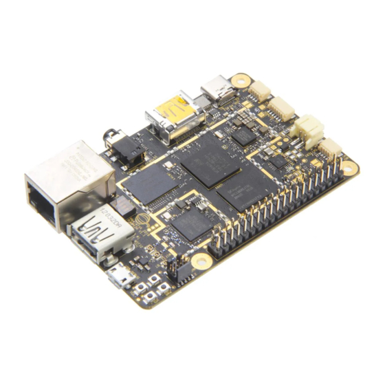
Page 14: Board View
Board View Top View Bottom View *The photos above are for reference only. Some minor components may differ. MBD301 User’s Manual... -
Page 15: Dimensions
General Information I/O View Name Name COM1 Port GbE Ports COM2 Port Microphone DisplayPort Line-Out USB 3.0 Ports Line-In Dimensions MBD301 User’s Manual... - Page 16 This page is intentionally left blank. MBD301 User’s Manual...
-
Page 17: Chapter 2 Hardware Configuration
Chapter 2 Hardware Configuration This section provides information on jumper settings and connectors on the board in order to set up a workable system. The topics covered are: • Installing the CPU, memory, Mini-PCIe cards and M.2 cards • Jumper and connector locations •... -
Page 18: Installations
Gently push the module into the slot until the ejector levers return completely to closed position, holding the module in place when the module touches the bottom of the slot. To remove the module, press the ejector levers outwards to unseat the module. MBD301 User’s Manual... -
Page 19: Installing Mini-Pcie & M.2 Cards
Align the key of the mini-PCIe card to the mini-PCIe interface, and insert the card slantwise. (Insert M.2 cards in the same way.) Push the mini-PCIe card down and fix it with the an M2 screw. (Fix the M.2 network card with an M3 screw.) Mini-PCIe: M.2: MBD301 User’s Manual... -
Page 20: Setting The Jumpers
1 2 3 When two pins of a jumper are encased in a jumper cap, this jumper is closed, i.e. turned On. When a jumper cap is removed from two jumper pins, this jumper is open, i.e. turned Off. MBD301 User’s Manual... -
Page 21: Jumper & Connector Locations
Hardware Configuration Jumper & Connector Locations MBD301: Figures of MBD301 MBD301 User’s Manual... -
Page 22: Jumpers & Connectors Quick Reference
USB 3.0 Connectors SATA 3.0 Connectors CN7, CN9, CN10 Dual USB 3.0 & RJ45 LAN Ports Audio Jacks CN11 DDR4 SO-DIMM Connectors J7, J8 Mini-PCIe Slot SIM Card Socket M.2 E2230 Slot Factory Use Only J2, J13, J14 MBD301 User’s Manual... -
Page 23: Clearing Cmos Data (Jp1)
Hardware Configuration 2.4.1 Clearing CMOS Data (JP1) Function Pin closed Illustration Normal (default) Clear CMOS MBD301 User’s Manual... -
Page 24: Com1 Rs-232/422/485 & Com2 Rs-232 Ports (Cn1)
RI, Ring indicator COM2: Signal Name Signal Name DCD, Data carrier detect DSR, Data set ready RXD, Receive data RTS, Request to send TXD, Transmit data CTS, Clear to send DTR, Data terminal ready RI, Ring indicator Ground MBD301 User’s Manual... -
Page 25: Com3 & Com4 Rs-232 Ports (J5, J4)
RXD, Receive data TXD, Transmit data DTR, Data terminal ready Ground DSR, Data set ready RTS, Request to send CTS, Clear to send RI, Ring indicator 2.4.4 RTC Battery Connector (J1) Signal Name Signal Name Battery+ Ground MBD301 User’s Manual... -
Page 26: Digital I/O Connector (J3)
2.4.5 Digital I/O Connector (J3) Signal Name Signal Name Ground VCC5 OUT3 OUT1 OUT2 OUT0 2.4.6 Front Panel Settings Connector (J6) Signal Name Signal Name PWR_BTN# HDD LED+ HDD LED- RST_BTN# PWR LED+ PWR LED- MBD301 User’s Manual... -
Page 27: Dual Usb 2.0 Connector (J17)
Dual USB 2.0 Connector (J17) Signal Name Signal Name USB- USB+ USB+ USB- 2.4.8 Fan Power Connectors (CPU_FAN1, SYS_FAN1, SYS_FAN2) CPU_FAN1 SYS_FAN2 SYS_FAN1 CPU_FAN1, SYS_FAN1 and SYS_FAN2 are PWM only. Signal Name Signal Name Ground Rotation detection Rotation Control MBD301 User’s Manual... -
Page 28: Atx Power Connectors (J10, J12)
ATX Power Connectors (J10, J12) J10: Signal Name Signal Name 3.3V 3.3V 3.3V -12V Ground Ground PS-ON Ground Ground Ground Ground Ground Power good 5VSB +12V +12V +3.3V Ground J12: Signal Name Signal Name Ground +12V Ground +12V MBD301 User’s Manual... -
Page 29: Chapter 3 Drivers Installation
Chapter 3 Drivers Installation This chapter introduces installation of the following drivers: • Graphics Driver Installation • HD Audio Driver Installation • LAN Driver Installation... -
Page 30: Introduction
AMD Ryzen Chipset Drivers Installation Insert the disk that came with your motherboard. Click on AMD and then click on AMD X470 Chipset Drivers. Click on AMD Ryzen Chipset Drivers. MBD301 User’s Manual... - Page 31 Driver Installation Click on the checkbox to agree with the terms and conditions. Now, click the Drivers tab on top. On the next screen, click on Install to install the AMD Ryzen Chipset Drivers. MBD301 User’s Manual...
- Page 32 The CHIPSET DRIVER INSTALLER screen appears during the installation. Once the chipset drivers have been successfully installed, click Restart Now for changes to take effect. MBD301 User’s Manual...
-
Page 33: Graphics Driver Installation
Driver Installation Graphics Driver Installation Insert the disk that came with your motherboard. Click on AMD and then click on AMD X470 Chipset Drivers. Click on AMD Ryzen 3/5/7 Graphics Drivers. MBD301 User’s Manual... - Page 34 The next screen shows the Destination Folder for the Radeon Software Adrenalin 2019 Edition. Click Install. MBD301 User’s Manual...
- Page 35 Driver Installation In the END USER LICENSE AGREEMENT screen, click Accept and Express Install for installation to start. When installation is finished, click Restart Now for the system to restart and changes to take effect. MBD301 User’s Manual...
-
Page 36: Hd Audio Driver Installation
HD Audio Driver Installation Insert the disk that came with your motherboard. Click on AMD and then click on AMD X470 Chipset Drivers. Click on Realtek High Definition Audio Driver. MBD301 User’s Manual... - Page 37 Driver Installation In the Welcome screen, click Next for the InstallShield Wizard to start the installation of the Realtek High Definition Audio Driver. When the installation has been completed, restart the system for changes to take effect. MBD301 User’s Manual...
-
Page 38: Lan Driver Installation
LAN Driver Installation Insert the disk that came with your motherboard. Click on LAN Card. On the Welcome screen of the InstallShield Wizard for Realtek Ethernet Controller Driver, click Next. MBD301 User’s Manual... - Page 39 Driver Installation Now, click Install to begin the installation. When the driver has been successfully installed, restart the system for changes to take effect. MBD301 User’s Manual...
-
Page 40: Chapter 4 Bios Setup
Chapter 4 BIOS Setup This chapter describes the different settings available in the AMI BIOS that comes with the board. The topics covered in this chapter are as follows: • Main Settings • Advanced Settings • Chipset Settings • Security Settings •... -
Page 41: Introduction
These defaults have been carefully chosen by both AMI and your system manufacturer to provide the absolute maximum performance and reliability. Changing the defaults could make the system unstable and crash in some cases. MBD301 User’s Manual... - Page 42 MBD301 User’s Manual...
-
Page 43: Main Settings
BIOS Setup 4.3 Main Settings BIOS Setting Description System Date Sets the date. Use the <Tab> key to switch between the data elements. System Time Set the time. Use the <Tab> key to switch between the data elements. MBD301 User’s Manual... -
Page 44: Advanced Settings
Enables / Disables system ability to hibernate Enable (OS/S4 Sleep State). This option may not be Hibernation effective with some operating systems. Selects the highest ACPI sleep state the system ACPI Sleep State will enter when the SUSPEND button is pressed. MBD301 User’s Manual... - Page 45 BIOS Setup 4.4.2 Chipset Common Options BIOS Setting Description IDE Configuration Configures IDE Devices. Selects SATA Type. SATA Mode Options: AHCI, RAID, Auto MBD301 User’s Manual...
- Page 46 For example, if setting up a schedule from Wednesday 5 p.m. to Thursday 2 a.m., configure two schedule slots. But if setting up a schedule from 3 p.m to 5 p.m. on Wednesday, configure only a schedule slot. MBD301 User’s Manual...
- Page 47 BIOS Setup 4.4.4 Fintek Super I/O Configuration BIOS Setting Description Sets parameters of Serial Ports. Serial Port 1 ~ 4 Enables / Disables the serial port and select an Configuration optimal setting for the Super IO device. MBD301 User’s Manual...
- Page 48 Voltages The values are read-only as monitored by the system and show the PC health status. Disables or sets system shutdown temperature to CPU Shutdown Temperature 70°C, 75°C, 80°C, 85°C, 90°C or 95°C. MBD301 User’s Manual...
- Page 49 BIOS Setup 4.4.6 CPU Configuration 4.4.7 USB Configuration MBD301 User’s Manual...
- Page 50 100ms; for a Hub port, the delay is taken from Hub descriptor. Mass storage device emulation type. ‘AUTO’ enumerates devices according to their media Mass Storage format. Optical drives are emulated as ‘CDROM’, Devices drives with no media will be emulated according to a drive type. MBD301 User’s Manual...
- Page 51 Options: Adjust, Keep Controls the priority of Legacy / UEFI ROMs. Boot option filter Options: UEFI and Legacy, Legacy only, UEFI only Controls the execution of UEFI and Legacy Network Network OpROM. Options: Do not launch, UEFI, Legacy MBD301 User’s Manual...
- Page 52 Network Stack Configuration BIOS Setting Description Network Stack Enable / Disable UEFI Network Stack 4.4.10 AMD CBS BIOS Setting Description NBIO Common Options Configures GFx and NB Integrated Graphics Enable Integrated Graphics controller Controller IOMMU Enable/Disable IOMMU MBD301 User’s Manual...
- Page 53 BIOS Setup 4.4.11 AMD PBS BIOS Setting Description Selects Internal/External Graphics Primary Video Adaptor Options: Int Graphics (IGD), Ext Graphics (PEG) MBD301 User’s Manual...
-
Page 54: Chipset Settings
4.5 Chipset Settings BIOS Setting Description SB USB Configuration Options for SB USB Configuration North Bridge Displays the parameters of North Bridge. MBD301 User’s Manual... -
Page 55: Security Settings
User mode. The mode change requires platform reset. Secure Boot Secure Boot mode options: Standard or Custom. In Custom mode, Secure Boot Policy variables can be configured by a physically present user without full authentication. MBD301 User’s Manual... -
Page 56: Boot Settings
Enables / Disables Quiet Boot option. Boot Mode Select Select boot mode: Legacy / UEFI. FIXED BOOT Sets the system boot order. ORDER Priorities UEFI Hard Disk Drive Specifies the Boot Device Priority sequence BBS Priorities from available UEFI Hard Disk Drives MBD301 User’s Manual... -
Page 57: Save & Exit Settings
Restore / Load defaults values for all the setup Restore Defaults options. Save as User Defaults Save the changes done so far as User Defaults. Restore the User Defaults to all the setup Restore User Defaults options. MBD301 User’s Manual... -
Page 58: Appendix
Appendix This section provides the mapping addresses of peripheral devices, the sample code of watchdog timer configuration, and types of on-board connectors. MBD301 User’s Manual... -
Page 59: I/O Port Address Map
PCI Express Root Complex 0x00000D00-0x0000FFFF PCI Express Root Complex 0x00000040-0x00000043 System timer 0x00000010-0x0000001F Motherboard resources 0x00000022-0x0000003F Motherboard resources 0x00000063-0x00000063 Motherboard resources 0x00000065-0x00000065 Motherboard resources 0x00000067-0x0000006F Motherboard resources 0x00000072-0x0000007F Motherboard resources 0x00000080-0x00000080 Motherboard resources 0x00000084-0x00000086 Motherboard resources 0x00000088-0x00000088 Motherboard resources MBD301 User’s Manual... - Page 60 0x00000B20-0x00000B3F Motherboard resources 0x00000900-0x0000090F Motherboard resources 0x00000910-0x0000091F Motherboard resources 0x00000061-0x00000061 System speaker 0x00000081-0x00000083 Direct memory access controller 0x00000087-0x00000087 Direct memory access controller 0x00000089-0x0000008B Direct memory access controller 0x0000008F-0x0000008F Direct memory access controller 0x000000C0-0x000000DF Direct memory access controller MBD301 User’s Manual...
-
Page 61: Interrupt Request Lines (Irq)
Standard SATA AHCI Controller IRQ 4294967284 AMD USB 3.10 eXtensible Host Controller - 1.10 (Microsoft) IRQ 4294967278 AMD USB 3.10 eXtensible Host Controller - 1.10 (Microsoft) IRQ 4294967277 AMD USB 3.10 eXtensible Host Controller - 1.10 (Microsoft) MBD301 User’s Manual... -
Page 62: Watchdog Timer Configuration
#include <dos.h> #include <conio.h> #include <stdio.h> #include <stdlib.h> #include "F81846.H" //--------------------------------------------------------------------------- int main (int argc, char *argv[]); void EnableWDT(int); void DisableWDT(void); //--------------------------------------------------------------------------- int main (int argc, char *argv[]) unsigned char bBuf; unsigned char bTime; char **endptr; char SIO; MBD301 User’s Manual... - Page 63 Set_F81846_Reg(0xF6, interval); //set timer bBuf = Get_F81846_Reg(0xFA); bBuf |= 0x01; Set_F81846_Reg(0xFA, bBuf); //enable WDTO output bBuf = Get_F81846_Reg(0xF5); bBuf |= 0x20; Set_F81846_Reg(0xF5, bBuf); //start counting //--------------------------------------------------------------------------- void DisableWDT(void) unsigned char bBuf; Set_F81846_LD(0x07); //switch to logic device 7 MBD301 User’s Manual...
- Page 64 //Fintek 81846 goto Init_Finish; F81846_BASE = 0x2E; result = F81846_BASE; ucDid = Get_F81846_Reg(0x20); if (ucDid == 0x07) //Fintek 81846 goto Init_Finish; F81846_BASE = 0x00; result = F81846_BASE; Init_Finish: return (result); //--------------------------------------------------------------------------- void Unlock_F81846 (void) outportb(F81846_INDEX_PORT, F81846_UNLOCK); outportb(F81846_INDEX_PORT, F81846_UNLOCK); MBD301 User’s Manual...
- Page 65 // IMPLIED WARRANTIES OF MERCHANTABILITY AND/OR FITNESS FOR A PARTICULAR // PURPOSE. //--------------------------------------------------------------------------- #ifndef F81846_H #define F81846_H //--------------------------------------------------------------------------- #define F81846_INDEX_PORT (F81846_BASE) #define F81846_DATA_PORT (F81846_BASE+1) //--------------------------------------------------------------------------- #define F81846_REG_LD 0x07 //--------------------------------------------------------------------------- #define F81846_UNLOCK 0x87 #define F81846_LOCK 0xAA //--------------------------------------------------------------------------- unsigned int Init_F81846(void); void Set_F81846_LD( unsigned char); MBD301 User’s Manual...
-
Page 66: On-Board Connector Types
E-call Settings 2.54 mm pitch 0126-01-203-080 Connector (female) Dual USB 2.0 Connector DF11-8DP-2DSA DF11-8DS-2C CPU_FAN1, Fan Power TECHBEST Molex SYS_FAN1, Connector W2-03I104132S1WT(A)-L 47054-1000 SYS_FAN2 Molex HAOGUO 01-0018-03 39-01-2240 ATX Power J10, J12 Connector HAOGUO ATX4PT-NY46 Molex 39-01-2040 MBD301 User’s Manual...
Need help?
Do you have a question about the MBD301 and is the answer not in the manual?
Questions and answers