
Related Manuals for IBASE Technology MB990


Summary of Contents for IBASE Technology MB990
- Page 1 MB990 Intel 6th Generation Core Q170 PCH ® ATX Motherboard USER’S MANUAL Version 1.0...
- Page 2 6th Generation Core DC/QC Processor are registered trademarks of Intel Corporation. Microsoft Windows is a registered trademark of Microsoft Corporation. Fintek is a registered trademark of Fintek Electronics Corporation. All other product names or trademarks are properties of their respective owners. MB990 User’s Manual...
-
Page 3: Table Of Contents
Board Dimensions .............. 5 Installations ............. 6 Installing the CPU .............. 7 Installing the Memory............8 Setting the Jumpers............. 9 Connectors on MB990 ............. 15 BIOS Setup .............27 BIOS Introduction ..............28 BIOS Setup................28 Advanced Settings..............30 CSM Configuration ..............37 Chipset Settings ................ - Page 4 This page is intentionally left blank. MB990 User’s Manual...
-
Page 5: Introduction
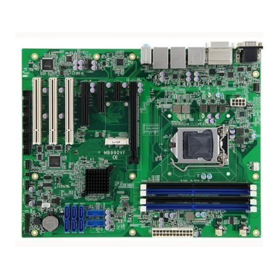
The MB990 Q170 platform is made with 14-nanometer technology that supports Intel’s first processor architecture to unite the CPU and the graphics core on the transistor level. The MB990 ATX board utilizes the dramatic increase in performance provided this Intel’s latest cutting-edge technology. -
Page 6: Checklist
INTRODUCTION Checklist Your MB990 package should include the items listed below. • The MB990 ATX motherboard • This User’s Manual • 1 DVD containing chipset drivers and flash memory utility • Serial ATA cable • COM ports cable • I/O shield... -
Page 7: Mb990 Specifications
- CPU FAN x 1 (PWM Fan type, 4-pin connector) - SYS FAN x 2 (DC Fan type, 3-pin connector) Digital IO 4 in & 4 out ® IAMT 11.0 Intel Q170 PCH built-in TPM 1.2 Infineon SLB9660 **Meet FIPS 140-2 certification** [For MB990VF only] MB990 User’s Manual... - Page 8 Reserve S3 status signal connector (4-pin) EuP/ErP (MB990EF only) OS supporting Windows 7 Pro (32b/64b) Windows 8.1(64b) / Embedded Industrial(64b) Windows 10 (64b) Linux Fedora (64b) / Ubuntu (64b) Certification CE (EN55032:2012) FCC Class B Board Size 305mm x 244mm RoHS MB990 User’s Manual...
-
Page 9: Board Dimensions
INTRODUCTION Board Dimensions MB990 User’s Manual... -
Page 10: Installations
INSTALLATIONS Installations This section provides information on how to use the jumpers and connectors on the MB990 in order to set up a workable system. The topics covered are: Installing the CPU ................7 Installing the Memory ................ 8 Setting the Jumpers ................9 Connectors on MB990 .............. -
Page 11: Installing The Cpu
INSTALLATIONS Installing the CPU The MB990 board supports an LGA1151 Socket (shown below) for Intel 6th Generation Core processors. To install the CPU, unlock first the socket by pressing the lever sideways, then lift it up to a 90-degree. Then, position the CPU above the socket such that the CPU corner aligns with the gold triangle matching the socket corner with a small triangle. -
Page 12: Installing The Memory
INSTALLATIONS Installing the Memory The MB990 board supports four DDR4 memory socket for a maximum total memory of 64GB in DDR4 DIMM memory type. Installing and Removing Memory Modules To install the DDR4 modules, locate the memory slot on the board and perform the following steps: 1. -
Page 13: Setting The Jumpers
INSTALLATIONS Setting the Jumpers Jumpers are used on MB990 to select various settings and features according to your needs and applications. Contact your supplier if you have doubts about the best configuration for your needs. The following lists the connectors on MB990 and their respective functions. -
Page 14: Jumper Locations On Mb990
INSTALLATIONS Jumper Locations on MB990 Jumpers on MB990................. Page JBAT2: Clear CMOS Contents ............11 JBAT1: Clear RTC Contents............11 JP1: COM1 RS232 RI/+5V/+12V Power Setting ......12 JP2: COM2 RS232 RI/+5V/+12V Power Setting ......12 JP3: Flash Descriptor Security Override (Factory use only) ....13 JP4, JP5: Processor dgfx Bifurcation Function Setting ..... -
Page 15: Jbat2: Clear Cmos Contents
INSTALLATIONS JBAT2: Clear CMOS Contents JBAT2 Setting Function Pin 1-2 Normal Short/Closed Pin 2-3 Clear CMOS Short/Closed JBAT1: Clear RTC Contents Flash Descriptor JBAT1 Security Override Normal Open (Default) Close Clear RTC MB990 User’s Manual... -
Page 16: Jp1: Com1 Rs232 Ri/+5V/+12V Power Setting
INSTALLATIONS JP1: COM1 RS232 RI/+5V/+12V Power Setting Setting Function Pin 1-3 +12V Short/Closed Pin 3-4 Short/Closed Pin 5-3 Short/Closed JP2: COM2 RS232 RI/+5V/+12V Power Setting Setting Function Pin 1-3 +12V Short/Closed Pin 3-4 Short/Closed Pin 5-3 Short/Closed MB990 User’s Manual... -
Page 17: Jp3: Flash Descriptor Security Override (Factory Use Only)
JP4, JP5: Processor dgfx Bifurcation Function Setting (MB990VF PCIE1 only) Processor dgfx Bifurcation Function Setting Open Open 1 X 16 (Default) Open Close 2 X 8 Close Open RSVD Close Close X 8, X 4, X 4 MB990 User’s Manual... - Page 18 INSTALLATIONS This page is intentionally left blank. MB990 User’s Manual...
-
Page 19: Connectors On Mb990
INSTALLATIONS Connectors on MB990 Connector Locations on MB990 ............16 CN3: COM1 and COM2 Serial Ports ..........17 CN5: DVI-D and HDMI Connector ..........17 CN6: USB3.0 Connector ..............18 CN2: Display Port Connector ............18 CN8: Gigabit LAN (Intel I219LM) + USB 0/1 ......... 18 CN7: Gigabit LAN (Intel I211AT) + USB 2/3........ -
Page 20: Connector Locations On Mb990
INSTALLATIONS Connector Locations on MB990 MB990 User’s Manual... -
Page 21: Cn3: Com1 And Com2 Serial Ports
DATA 0+ DATA 4- SHIELD 0/5 DATA 4+ DATA 5- DDC CLOCK DATA 5+ DDC DATA SHIELD CLK CLOCK + DATA 1- CLOCK - DATA 1+ SHIELD 1/3 DATA 3- DATA 3+ DDC POWER A GROUND 1 MB990 User’s Manual... -
Page 22: Cn6: Usb3.0 Connector
CN4: HD Audio Connector CN9, CN10, CN11, CN12, CN13, CN14: SATA Connectors J1: Audio Pin Header for Chassis Front Panel Signal Name Pin # Pin # Signal Name MIC IN_L Ground MIC IN_R LINE_R Sense Ground Sense LINE_L Sense Ground MB990 User’s Manual... -
Page 23: J2: Spdif I/O
Pin # Signal Name SPDIF IN Ground SPDIF OUT Ground ATX_12V_2X1: ATX 12V Power Connector This connector supplies the CPU operating voltage. Signal Name Pin # Pin # Signal Name Ground +12V Ground +12V Ground +12V Ground +12V MB990 User’s Manual... -
Page 24: J9, J8, J6, J4: Com3~Com6 Rs232 Serial Ports
J9, J8, J6, J4: COM3~COM6 RS232 Serial Ports Signal Name Pin # Pin # Signal Name DCD# DSR# RTS# SOUT CTS# DTR# J7: Mini PCI-E Connector(PCI-E X1 only) J13, J16: USB2.0 Connectors Signal Name Pin # Pin # Signal Name MB990 User’s Manual... -
Page 25: J21, J23: Usb3.0 Connectors
Signal Name Pin # Pin # Signal Name VCC(900mA) P1_SSRX- VCC(900mA) P1_SSRX+ P2_SSRX- P2_SSRX+ P1_SSTX- P1_SSTX+ P2_SSTX- P2_SSTX+ P1_U2_D- P1_U2_D+ P2_U2_D- P2_U2_D+ J10: Digital I/O Signal Name Pin # Pin # Signal Name OUT3 OUT1 OUT2 OUT0 MB990 User’s Manual... -
Page 26: J22: Front Panel Function Connector
INSTALLATIONS J22: Front Panel Function Connector Signal Name Pin # Pin # Signal Name PWR LED + PWR LED- (GND) SPK (VCC) PWR_SW PWR_SW HDD LED + HDD LED - J18: SPI Flash Connector (Factory use only) MB990 User’s Manual... -
Page 27: J24: Atx Power Supply Connector
Pin # Signal Name 3.3V 3.3V -12V 3.3V Ground Ground PS-ON Ground Ground Ground Ground Ground Power good 5VSB +12V +12V Ground +3.3V CPU_FAN1: CPU Fan Power Connector Pin # Signal Name Ground +12V Rotation detection Control MB990 User’s Manual... -
Page 28: Sys_Fan1: System Fan1 Power Connector
INSTALLATIONS SYS_FAN1: System Fan1 Power Connector Pin # Signal Name Ground +12V Rotation detection SYS_FAN2: System Fan2 Power Connector Pin # Signal Name Ground +12V MB990 User’s Manual... -
Page 29: J11: Acpi Status Led
INSTALLATIONS J11: ACPI Status LED Pin # Signal Name +3VDUAL +VCC3 PCIE1: PCI-E X16 Slot PCIE4: PCI-E X8 Slot (PCI-E X4) MB990 User’s Manual... -
Page 30: Pcie3: Pci-E X4 Slot (Pci-E X1)
INSTALLATIONS PCIE3: PCI-E X4 Slot (PCI-E X1) PCIE2: PCI-E X1 Slot PCI1-PCI3: PCI 32-bit Slot MB990 User’s Manual... -
Page 31: Bios Setup
The topics covered in this chapter are as follows: BIOS Introduction ................28 BIOS Setup ..................28 Advanced Settings ................30 CSM Configuration................37 Chipset Settings ................. 41 Security Settings ................44 Boot Settings ..................45 Save & Exit Settings ................46 MB990 User’s Manual... -
Page 32: Bios Introduction
These defaults have been carefully chosen by both AMI and your system manufacturer to provide the absolute maximum performance and reliability. Changing the defaults could cause the system to become unstable and crash in some cases. MB990 User’s Manual... -
Page 33: System Language
F3: Optimized Default F4: Save ESC: Exit System Language Choose the system default language. System Date Set the Date. Use Tab to switch between Data elements. System Time Set the Time. Use Tab to switch between Data elements. MB990 User’s Manual... -
Page 34: Advanced Settings
OS. ACPI Sleep State Select ACPI sleep state the system will enter, when the SUSPEND button is pressed. Lock Legacy Resources Enabled or Disabled Lock of Legacy Resources. S3 Video Repost Enable or disable S3 Video Repost. MB990 User’s Manual... - Page 35 This field sets the system power status whether Disable or Enable when power returns to the system from a power failure situation. Temperature Guardian Generate the reset signal when system hangs up on POST Schedule Slot 1 / 2 Setup the hour/minute for system power on. MB990 User’s Manual...
- Page 36 Set timer to wait before sending ASF_GET_BOOT_OPTIONS. Activate Remote Assistance Process Trigger CIRA boot. PET Progress User can Enable/Disable PET Events progress to receive PET events or not. Watchdog Timer This configuration is supported only with MB990VF (with iAMT function). Enable/Disable Watchdog Timer. MB990 User’s Manual...
-
Page 37: F81866 Super Io Configuration
► Serial Port 6 Configuration Standby Power on S5 This configuration is supported only with MB990EF. Serial Port Configuration Set Parameters of Serial Ports. User can Enable/Disable the serial port and Select an optimal settings for the Super IO Device. MB990 User’s Manual... -
Page 38: Hardware Monitor
These fields are the parameters of the hardware monitoring function feature of the motherboard. The values are read-only values as monitored by the system and show the PC health status. CPU Shutdown Temperature The default setting is Disabled. MB990 User’s Manual... -
Page 39: Cpu Configuration
64-bit Supported Change Field EIST Technology Supported F1: General Help F2: Previous Values Intel(R) SpeedStep(tm) Enabled F3: Optimized Default Turbo Mode Enabled F4: Save ESC: Exit Intel(R) SpeedStep(tm) Allows more than two frequency ranges to be supported. MB990 User’s Manual... -
Page 40: Sata Configuration
Software Preserve Unknown ESC: Exit Hot Plug Disabled SATA Controller(s) Enable or disable SATA Device. SATA Mode Selection Determines how SATA controller(s) operate. (1) AHCI Mode. (2) RAID Mode. Hot Plug Designates this port as Hot Pluggable. MB990 User’s Manual... -
Page 41: Csm Configuration
→ ← Select Screen Network Do not launch ↑↓ Select Item Enter: Select Change Field F1: General Help F2: Previous Values F3: Optimized Default F4: Save ESC: Exit Network Controls the execution of UEFI and Legacy PXE OpROM MB990 User’s Manual... -
Page 42: Trusted Computing
F1: General Help F2: Previous Values F3: Optimized Default F4: Save ESC: Exit Security Device Support This configuration is supported only with MB990VF. Enables or Disables TPM support. O.S. will not show TPM. Reset of platform is required. MB990 User’s Manual... -
Page 43: Usb Configuration
Enables I/O port 60h/64h emulation support. This should be enabled for the complete USB keyboard legacy support for non-USB aware OSes. USB Transfer time-out The time-out value for Control, Bulk, and Interrupt transfers. Device reset tine-out USB mass Storage device start Unit command time-out. MB990 User’s Manual... - Page 44 Maximum time the device will take before it properly reports itself to the Host Controller. ‘Auto’ uses default value: for a Root port it is 100ms, for a Hub port the delay is taken from Hub descriptor. MB990 User’s Manual...
-
Page 45: Chipset Settings
↑↓ Select Item VT-d Supported Enter: Select Change Field F1: General Help VT-d Enabled F2: Previous Values ► Graphics Configuration F3: Optimized Default ► Memory Configuration F4: Save ESC: Exit VT-d Check to enable VT-d function on MCH. MB990 User’s Manual... -
Page 46: Graphics Configuration
Select DVMT 5.0 Pre-Allocated (Fixed) graphics memory size used by the internal graphics device. DVMT Total Gfx Mem Select DVMT 5.0 total graphics memory size used by the internal graphics device. Gfx Low Power Mode This option is applicable for SFF only. MB990 User’s Manual... -
Page 47: Memory Configuration
Wake on LAN Enable or disable integrated LAN to wake the system. (The Wake On LAN cannot be disabled if ME is on at Sx state.) SLP_LAN# Low on DC Power Enable or Disable SLP_LAN# Low on DC Power MB990 User’s Manual... -
Page 48: Security Settings
Change Field Minimum length F1: General Help Maximum length F2: Previous Values F3: Optimized Default Administrator Password F4: Save ESC: Exit User Password Administrator Password Set Setup Administrator Password. User Password Set User Password. MB990 User’s Manual... -
Page 49: Boot Settings
Enables/Disables boot with initialization of a minimal set of devices required to launch active boot option. Has no effect for BBS boot options. New Boot Option Policy Controls the placement of newly detected UEFI boot oprion. FIXED BOOT ORDER Priorities Sets the system boot order. MB990 User’s Manual... -
Page 50: Save & Exit Settings
Discard Changes done so far to any of the setup options. Restore Defaults Restore/Load Defaults values for all the setup options. Save as User Defaults Save the changes done so far as User Defaults. Restore User Defaults Restore the User Defaults to all the setup options. MB990 User’s Manual... -
Page 51: Drivers Installation
LAN Drivers Installation ..............55 Intel® Management Engine Interface ..........58 Intel® USB 3.0 Drivers ..............60 IMPORTANT NOTE: After installing your Windows operating system, you must install first the Intel Chipset Software Installation Utility before proceeding with the drivers installation. MB990 User’s Manual... -
Page 52: Intel Chipset Software Installation Utility
Plug & Play INF support for Intel chipset components. Follow the instructions below to complete the installation. 1. Insert the DVD that comes with the board. Click Intel and then Intel(R) Skylake Chipset Drivers. 2. Click Intel(R) Chipset Software Installation Utility. MB990 User’s Manual... - Page 53 4. Click Yes to accept the software license agreement and proceed with the installation process. 5. On the Readme File Information screen, click Install to continue the installation. 6. The Setup process is now complete. Click Finish to restart the computer and for changes to take effect. MB990 User’s Manual...
-
Page 54: Vga Drivers Installation
DRIVER INSTALLATION VGA Drivers Installation 1. Insert the DVD that comes with the board. Click Intel and then Intel(R) Skylake Chipset Drivers. 2. Click Intel(R) HD Graphics Driver. MB990 User’s Manual... - Page 55 DRIVERS INSTALLATION 3. When the Welcome screen appears, click Next to continue. 4. Click Yes to to agree with the license agreement and continue the installation. MB990 User’s Manual...
- Page 56 DRIVER INSTALLATION 5. On the screen shown below, click Install to continue. 6. Setup complete. Click Finish to restart the computer and for changes to take effect. MB990 User’s Manual...
-
Page 57: Realtek Hd Audio Driver Installation
DRIVERS INSTALLATION Realtek HD Audio Driver Installation 1. Insert the DVD that comes with the board. Click Intel and then Intel(R) Skylake Chipset Drivers. 2. Click Realtek High Definition Audio Driver. MB990 User’s Manual... - Page 58 DRIVER INSTALLATION 3. On the Welcome to the InstallShield Wizard screen, click Next to proceed with and complete the installation process. 4. The InstallShield Wizard Complete. Click Finish to restart the computer and for changes to take effect. MB990 User’s Manual...
-
Page 59: Lan Drivers Installation
DRIVERS INSTALLATION LAN Drivers Installation 1. Insert the DVD that comes with the board. Click Intel and then Intel(R) Skylake Chipset Drivers. 2. Click Intel(R) PRO LAN Network Driver. MB990 User’s Manual... - Page 60 DRIVER INSTALLATION 3. Click Install Drivers and Software. 4. When the Welcome screen appears, click Next. MB990 User’s Manual...
- Page 61 6. Click the checkbox for Drivers in the Setup Options screen to select it and click Next to continue. 7. The wizard is ready to begin installation. Click Install to begin the installation. 8. When InstallShield Wizard is complete, click Finish. MB990 User’s Manual...
-
Page 62: Intel® Management Engine Interface
DRIVER INSTALLATION Intel® Management Engine Interface 1. Insert the DVD that comes with the board. Click Intel and then Intel(R) Skylake Chipset Drivers. MB990 User’s Manual... - Page 63 Management Engine Components, click the checkbox for Install Intel® Control Center & click Next. 3. Click Next to to agree with the license agreement. 4. When the Setup Progress screen appears, click Next. Then, click Finish when the setup progress has been successfully installed. MB990 User’s Manual...
-
Page 64: Intel® Usb 3.0 Drivers
DRIVER INSTALLATION Intel® USB 3.0 Drivers 1. Insert the DVD that comes with the board. Click Intel and then Intel(R) Skylake Chipset Drivers. 2. Click Intel(R) USB 3.0 Drivers. MB990 User’s Manual... - Page 65 DRIVERS INSTALLATION 3. When the Welcome screen to the InstallShield Wizard for Intel® USB 3.0 eXtensible Host Controller Driver, click Next. 4. Click Next to to agree with the license agreement and continue the installation. MB990 User’s Manual...
- Page 66 5. On the Readme File Information screen, click Next to continue the installation of the Intel® USB 3.0 eXtensible Host Controller Driver. 6. Setup complete. Click Finish to restart the computer and for changes to take effect. MB990 User’s Manual...
-
Page 67: Appendix
F000h-F03Fh Intel(R) HD Graphics 530 F040h-F05Fh Intel(R) 100 Series/C230 Series Chipset SMBus - A123 F060h-F07Fh Standard SATA AHCI Controller F080h-F083h Standard SATA AHCI Controller F090h-F097h Standard SATA AHCI Controller F0A0h-F0A7h Intel(R) Active Management Technology - SOL (COM7) MB990 User’s Manual... -
Page 68: Interrupt Request Lines (Irq)
High Definition Audio Controller IRQ 16 Standard SATA AHCI Controller IRQ 17 Intel(R) 100 Series/C230 Series Chipset Family PCI Express Root Port #6 - A115 IRQ 19 Intel(R) Active Management Technology - SOL (COM7) IRQ 19 PCI standard PCI-to-PCI bridge MB990 User’s Manual... -
Page 69: Watchdog Timer Configuration
Fintek 81866, program abort.\n"); return(1); }//if (SIO == 0) if (argc != 2) printf(" Parameter incorrect!!\n"); return (1); bTime = strtol (argv[1], endptr, 10); printf("System will reset after %d seconds\n", bTime); if (bTime) EnableWDT(bTime); } else DisableWDT(); return 0; MB990 User’s Manual... - Page 70 //--------------------------------------------------------------------------- void DisableWDT(void) unsigned char bBuf; Set_F81866_LD(0x07); //switch to logic device 7 bBuf = Get_F81866_Reg(0xFA); bBuf &= ~0x01; Set_F81866_Reg(0xFA, bBuf); //disable WDTO output bBuf = Get_F81866_Reg(0xF5); bBuf &= ~0x20; bBuf |= 0x40; Set_F81866_Reg(0xF5, bBuf); //disable WDT //--------------------------------------------------------------------------- MB990 User’s Manual...
-
Page 71: Mb990 User's Manual
F81866_UNLOCK); outportb(F81866_INDEX_PORT, F81866_UNLOCK); //--------------------------------------------------------------------------- void Lock_F81866 (void) outportb(F81866_INDEX_PORT, F81866_LOCK); //--------------------------------------------------------------------------- void Set_F81866_LD( unsigned char LD) Unlock_F81866(); outportb(F81866_INDEX_PORT, F81866_REG_LD); outportb(F81866_DATA_PORT, LD); Lock_F81866(); //--------------------------------------------------------------------------- void Set_F81866_Reg( unsigned char REG, unsigned char DATA) Unlock_F81866(); outportb(F81866_INDEX_PORT, REG); outportb(F81866_DATA_PORT, DATA); Lock_F81866(); //--------------------------------------------------------------------------- MB990 User’s Manual... - Page 72 (F81866_BASE) #define F81866_DATA_PORT (F81866_BASE+1) //--------------------------------------------------------------------------- #define F81866_REG_LD 0x07 //--------------------------------------------------------------------------- #define F81866_UNLOCK 0x87 #define F81866_LOCK 0xAA //--------------------------------------------------------------------------- unsigned int Init_F81866(void); void Set_F81866_LD( unsigned char); void Set_F81866_Reg( unsigned char, unsigned char); unsigned char Get_F81866_Reg( unsigned char); //--------------------------------------------------------------------------- #endif //__F81866_H MB990 User’s Manual...
Need help?
Do you have a question about the MB990 and is the answer not in the manual?
Questions and answers