Table of Contents

Related Manuals for AVANT A430235


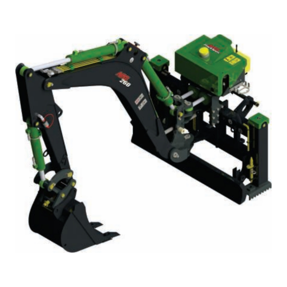
Summary of Contents for AVANT A430235
- Page 1 English Backhoe 260 with remote control 2022 1 Operator's Manual for Attachment Backhoe 260 with remote control Product number: For 500-700 series loaders A430235 For 800 series loaders A443267 A453108 2022 1 EN 2021- www.avanttecno.com...
- Page 2 Backhoe 260 with remote control 2022 1...
-
Page 3: Table Of Contents
Backhoe 260 with remote control 2022 1 CONTENTS 1. FOREWORD ............................5 Warning symbols used in this manual ..........................6 2. DESIGNED PURPOSE OF USE ......................7 3. SAFETY INSTRUCTIONS FOR USING THE ATTACHMENT ............9 Personal protective equipment ........................... 12 Safe shutdown procedure ............................ 13 4. - Page 4 8. WARRANTY TERMS ..........................51...
-
Page 5: Foreword
If you sell or transfer the equipment, be sure to hand over this manual to the new owner. If the manual is lost or damaged, you can request a new one from your Avant dealer or from the manufacturer. -
Page 6: Warning Symbols Used In This Manual
6 (54) Warning symbols used in this manual The following warning symbols are used throughout this manual. They indicate factors that must be taken into account to reduce the risk of personal injury or damage to property: WARNING SAFETY ALERT SYMBOL This symbol means: “Warning, be alert! Your safety is involved!”... -
Page 7: Designed Purpose Of Use
2. Designed purpose of use The AVANT Backhoe 260 with remote control is an attachment that is intended to be used with AVANT compact loaders that are listed in Table 1. The backhoe is controlled with its independent radio remote control to control the proportional control valve system of the backhoe. - Page 8 8 (54) Table 1 - Backhoe 260 with remote control - Compatibility with Avant loaders Model 313S 525LPG 320S 860i 225LPG 645i 755i 650i 760i A430235 (•) • • • • • • A443267 It is recommended to use the attachment only with loaders marked with • in Table 1. When using with models marked with (•), full performance may not be achieved.
-
Page 9: Safety Instructions For Using The Attachment
9 (54) 3. Safety instructions for using the attachment Please bear in mind that safety is the result of several factors. The loader-attachment combination is highly powerful and improper or careless use or maintenance may cause serious personal injury or property damage. - Page 10 10 (54) Tipping over hazard - Note that the excavation or trench may suddenly cave in. Exercise extreme caution when driving near ditches or embankments, and avoid driving along a ditch or trench, as the machine could suddenly tip over if an edge caves in.
- Page 11 11 (54) The stability of the loader may change when leaving the driver’s seat, leading to tipping over of the machine. Always remember that the boom may lower unexpectedly due to loss of stability, mechanical fault, or if another person operates the controls of the loader, leading to crushing hazard.
-
Page 12: Personal Protective Equipment
12 (54) 3.1 Personal protective equipment Remember to wear proper personal protective equipment: The noise level at the driver's seat may exceed 85 dB(A) depending on loader model and operating cycle. Extended exposure to loud noise can cause hearing impairment. Wear hearing protection while working with the loader. ... -
Page 13: Safe Shutdown Procedure
13 (54) 3.2 Safe shutdown procedure Safe stopping of the attachment, before going near the attachment: Always stop the attachment following safe stopping procedure before leaving the driver's seat. Safe stopping procedure prevents all unintentional movements of the attachment. Note that the loader boom can move down even if the engine of the loader is turned off. -
Page 14: Technical Specifications
Battery, remote control unit: 7.2V / 750 mAh, NiMH, (2 pcs A425086) Battery charger: 80 - 250 V AC 50/60Hz, A426435 Battery charging time: ~4 hours Suitable Avant loaders: See Table 1 Options: Waist belt for the radio transmitter: A425087... -
Page 15: Information About Radio Remote Control
This model of the backhoe must not be operated or exported to the area where the corresponding frequency range is not in use. Other Backhoe models may be available for different market areas, contact your Avant dealer for more information. -
Page 16: Safety Labels And Main Components Of The Attachment
16 (54) 4.2 Safety labels and main components of the attachment Listed below are the labels and markings on the attachment. They must be visible and readable on the equipment. Replace any unclear or missing label. New labels are available via your retailer or contact information provided on the cover. - Page 17 17 (54) Table 4 - Backhoe 260 with remote control - Main components A433267 Frame with Avant quick coupling brackets Support arm (2 pcs) / (1 pc) RC valve control unit (Receiver) with light beacon Lifting boom Front boom (stick)
-
Page 18: Attaching The Attachment
Do not stay in the area between the attachment and the loader. Mount the attachment only on level surface. WARNING Never move or lift an attachment that has not been locked. Avant quick coupling system: Step 1: Lift the locking pins of the quick coupling plate of the loader up, and turn them backwards into the slot, so that they are locked in the upper position. - Page 19 19 (54) Step 4 (A443267): After the locking pins are positively locked, fit the support arms (1) as shown in the figure below. Align the support arms (1) with the holes on the loader boom (2). Lock the backhoe on the loader boom (2) by tightening the support arms (1) with allen key (3).
- Page 20 20 (54) Step 4 (A430235): After the locking pins are positively locked, fit the support arm (1) of the RC control valve unit (2) to the bracket (3) on the loader's boom. Align the hole of the support arm (1) with the hole of the bracket on the loader's boom (5).
-
Page 21: Connecting And Disconnecting Hydraulic Hoses
5.2 Connecting and disconnecting hydraulic hoses On Avant loaders the hydraulic hoses are connected using the multi connector system. Risk of movement of the attachment and ejection of hydraulic oil - Never connect or disconnect quick couplings or other hydraulic components while the control... - Page 22 22 (54) To disconnect the multiconnector system: Before disconnecting put the attachment down on a solid and even surface. 1. Switch off the auxiliary hydraulics of the loader. 2. While pushing unlock button, turn the lever to disconnect the connector. 3.
-
Page 23: Electric Connection
23 (54) 5.3 Electric connection Electric functions of the attachment: The receiving unit of the backhoe, including the radio receiver and electrically controlled hydraulic valves, need electric supply from the loader in order to operate. Electric power to the receiver can be supplied with the Opticontrol of the loader, or with the standard electric harness that is supplied with the attachment. - Page 24 24 (54) If your loader is equipped with the Opticontrol ® If the loader is equipped with the Opticontrol , and ® the electric socket integrated in the multiconnector, the electric harness of the attachment is connected when the multiconnector is coupled. Clean both multiconnectors before connecting...
-
Page 25: Uncoupling And Storage
25 (54) 5.4 Uncoupling and storage Uncouple and store the attachment on level ground. The best way to store the attachment is a place where it is protected from direct sunlight, rain, and extreme temperatures. Avoid leaving the attachment laying directly on the ground. Place it on blocks of wood or on a pallet, for example. -
Page 26: Using The Storage/Transport Support
26 (54) Correct storage position: Turn the backhoe to the position as shown in the figure below: Bucket flat on the ground, straight front, not too close to the frame Boom in such position that the storage supports can be locked Storage the radio controller separately from the attachment. -
Page 27: Transport Position
27 (54) 5.4.3 Transport position Turn the backhoe to its middle position (straight forward) so that it will not affect the stability of the loader. The middle position will obstruct visibility from the driver's seat as little as possible. Keep the loader stable. Always transport the backhoe as low and close to the ground as possible. -
Page 28: Instructions For Use
28 (54) 6. Instructions for use Check the attachment and the operating environment once more before starting to work, and that all obstacles have been removed from the operating area. Quick inspection of the equipment and the operating area before use are parts of ensuring safety and the best performance of the equipment. -
Page 29: Checks Before Use
29 (54) Risk of flying objects - Make sure that there are no outsiders in the operating area. Braking of hard soil by digging it with the backhoe may cause loose debris thrown at high speed. Always keep safety distance of 5 meters from bystanders. CAUTION 6.1 Checks before use ... -
Page 30: Operating The Backhoe
30 (54) 6.2 Operating the backhoe The backhoe can be controlled only with the remote control unit, either via radio link or with a cable. There are no manual control levers on this attachment. 1. Check that the backhoe is fully coupled to the loader before setting up the control unit ... -
Page 31: Controls
31 (54) 6.2.1 Controls Move the auxiliary hydraulics control lever of the loader to its locking position when ready to start operating the backhoe. Release the auxiliary hydraulics control lever whenever not operating the backhoe. The auxiliary hydraulics oil flow should not exceed 45 l/min. See the operator's manual of the loader for correct loader engine RPM setting. -
Page 32: Outriggers
32 (54) Left control joystick: Right control joystick: front boom (stick) main boom slewing bucket Switch on the left joystick: Bucket tilt adapter/Thumb (optional equipment) Crushing hazard - Prevent unintentional movements of the attachment. Switch off the auxiliary hydraulics as soon as not using the backhoe to disable the controls of the backhoe. -
Page 33: Starting To Use The Backhoe With Remote Controller
33 (54) 6.2.3 Starting to use the backhoe with remote controller Risk of impact and crushing - Stay clear of the backhoe when setting it up. The backhoe may start unexpectedly during set up causing serious injuries from crushing or WARNING impact. - Page 34 34 (54) Start the radio transmitter as follows: Switch on the remote control system after the backhoe has been set up ready for digging work. See page 32. Connect the electric harness to the radio receiver of the loader. If the loader is equipped with the Opticontrol system, the receiver is...
-
Page 35: Using Digging Equipment
35 (54) Risk of unexpected movement - Improper use. To prevent loss of control, accidental contact, or improper use, the user must always wear a waist belt or shoulder harness with the radio transmitter during operation. WARNING Risk of impact and crushing - Stay away from the reach area of the backhoe. - Page 36 36 (54) Penetrate the ground with the bucket Depending on soil material, the most efficient angle varies. In typical digging conditions, start with the bucket at about a 45° angle to the ground. When digging hard ground, it may be necessary to decrease the bucket angle of entry to the point where the back of the...
-
Page 37: Light Signals
37 (54) Operate the backhoe only with its own hydraulic system and set of controls. Do not excavate by using the driving force of the loader. Working this way can damage the loader boom or the backhoe. Avoid sideways loading of the bucket. Working with the swivel force can damage the backhoe or the loader boom. -
Page 38: Light Beacon
38 (54) Receiving unit The receiving unit provides information as follows: The POWER LED indicates the status of the POWER receiving unit and the radio link. The ALARM LED warns about anomalies in the receiving unit. ALARM The meaning of signals provided by the ALARM LED are described in separate ARX Receiving Unit manual. -
Page 39: Operating On Inclined Terrain
39 (54) 6.6 Operating on inclined terrain Extra caution is needed when moving the equipment on inclined terrains and slopes. Drive slowly especially on inclined, uneven, or slippery surfaces, and avoid sudden changes in speed or direction. Operate the controls of the loader with careful and smooth movements. Watch out for ditches, holes on the ground, and other obstacles, as hitting an obstacle may cause the loader to tip over. - Page 40 40 (54) Table 5 - Backhoe 260 with remote control - Bucket options A414304 A35583 A414301 A35230 (standard bucket) Width: 250 mm 400 mm 750 mm 1000 mm Edge: 2 teeth 3 teeth straight straight Weight: 54 kg 66 kg 90 kg 130 kg A21638...
-
Page 41: Installation Of Hydraulic Options
41 (54) 6.8 Installation of hydraulic options Pinching and crushing hazard - Make sure any part of attachment cannot move. Make sure the attachment is securely lowered on the WARNING ground. Shut down the loader engine and set the moving components so that they will not cause hydraulic pressure to the system. -
Page 42: Excavator Thumb (Optional Extra)
42 (54) 6.8.1 Excavator thumb (Optional extra) The Backhoe 260 can be equipped with an excavator thumb. The hydraulic excavator thumb makes it possible to handle irregural material such as rocks, concrete, branches, and debris that does not otherwise fit into the bucket. - Page 43 43 (54) Make sure that the slide bearings (3) are fixed to the mounting ends of the thumb (7). Slide the pivot pin (4) through the whole structure so that the boom, S30 quick coupling and bushings are fitted between the mounting ends of the thumb (7) as shown in the adjacent figure.
-
Page 44: Tilting Bucket Adapter (Optional Extra)
44 (54) 6.8.2 Tilting bucket adapter (Optional extra) The Backhoe 260 can be equipped with a tilting bucket adapter. With the tilting adapter, a grading bucket can be used to level the ground surface to desired slopes or, for example, to dig a ditch. The tilting adapter includes the same S30-150 quick coupling system for the bucket as the backhoe itself, so the same buckets can be used with the tilting system. - Page 45 45 (54) Table 6 – Tilt adapter components 1. S30 quick coupling for bucket 2. Upper frame, installed to the backhoe 3. Hydraulic quick couplings, 2 pcs 4. Tilting cylinder 5. Pivot pin 6.8.2.1 Installing tilt adapter The tilting bucket adapter is mounted between the front boom of the backhoe and the bucket. The tilting bucket adapter replaces the standard coupling, and is also equipped with S30-150 quick coupling for the bucket.
-
Page 46: Maintenance And Service
Repair all leaks immediately after detecting them; a small leak can quickly grow into a big one. Operate the attachment only with type of hydraulic oil that is accepted for use in Avant loaders. Risk of high pressure fluid injection through skin - Release residual pressure before maintenance. -
Page 47: Cleaning The Attachment
Finding any fault means that the hydraulic hose or component must be replaced and the equipment must not be used until it is repaired. Spare parts are available from your nearest AVANT retailer or authorised service point. Leave the repair work to professional service technicians, if you don’t have adequate knowledge and experience about hydraulic assemblies and how to perform the repairing safely. -
Page 48: Lubrication
48 (54) 7.4 Lubrication There are a total of 19 lubrication points at the joints of the backhoe. If a tilting bucket adapter is installed, there are 3 additional lubricating points. A small amount of grease should be added regularly. Correct lubrication interval depends heavily on operating conditions but lubricant must be added at least after every 10 hours of use. -
Page 49: Radio Remote Control Maintenance
49 (54) 7.5 Radio remote control maintenance Before any maintenance operation, disconnect the receiving unit from the power supply, and uncouple the hydraulic multiconnector. After maintenance or service, check that all control commands sent by the transmitting unit activate only the corresponding expected operations. Stop use and contact service in the unlikely case that the programming or memory of the control unit has been reset and movements do not correspond with controls. - Page 50 50 (54) Recharging the battery of the remote control Connect the battery charger to the AC mains socket. The POWER LED turns on with steady light. Insert the battery in its designated housing in the battery charger a. Push the battery towards the contacts on the battery charger b.
- Page 51 51 (54) 8. Warranty terms Avant Tecno Oy grants a warranty of one year (12 months) from the date of purchase for the attachment it manufactures. The warranty covers repair costs as follows: Work costs are covered, if the repair is not performed at the factory.
- Page 52 Mallit / Modeller / Models Avant Hydraulitoiminen kaivuulaite kauko-ohjauksella; Avant-kuormaajan työlaite Hydraulisk grävaggregat med fjärrkontrol; arbetsredskap för Avant lastare A430235 Hydraulic backhoe with remote control; attachment for Avant loaders A443267 3.8.2022 Ylöjärvi, Finland Jani Käkelä, Toimitusjohtaja / Verkställande direktör /...
Need help?
Do you have a question about the A430235 and is the answer not in the manual?
Questions and answers