AVANT Backhoe 260 Operator's Manual For Attachment
Hide thumbs
Also See for Backhoe 260:
- Operator's manual for attachment (46 pages) ,
- Operator's manual (50 pages) ,
- Operator's manual for attachment (54 pages)

Related Manuals for AVANT Backhoe 260


Summary of Contents for AVANT Backhoe 260
- Page 1 English Backhoe 260 2019 1 Operator's Manual for Attachment Backhoe 260 Product number: A37510 www.avanttecno.com A437134 2019 1 EN 2019-...
- Page 2 Backhoe 260 2019 1...
-
Page 3: Table Of Contents
Backhoe 260 2019 1 CONTENTS 1. FOREWORD ............................4 Warning symbols used in this manual ..........................5 2. DESIGNED PURPOSE OF USE ......................6 3. SAFETY INSTRUCTIONS FOR USING THE ATTACHMENT ............8 4. TECHNICAL SPECIFICATIONS ......................12 Safety labels and main components of the attachment ..................13 5. -
Page 4: Foreword
If you sell or transfer the equipment, be sure to hand over this manual to the new owner. If the manual is lost or damaged, you can request a new one from your Avant dealer or from the manufacturer. -
Page 5: Warning Symbols Used In This Manual
5 (46) Warning symbols used in this manual The following warning symbols are used throughout this manual. They indicate factors that must be taken into account to reduce the risk of personal injury or damage to property: WARNING SAFETY ALERT SYMBOL This symbol means: “Warning, be alert! Your safety is involved!”... -
Page 6: Designed Purpose Of Use
The backhoe must not be used for lifting of objects. The backhoe is not intended for dredging, it must not be immersed in water. The Backhoe 260 is not designed for any other use than what is specified in this manual and must not be used for any other purposes than intended. - Page 7 If the loader is equipped with a cab, the windscreen, or its lower part, must be removed to make it possible to attach and operate the backhoe. Also, the loader must be fitted with a telescopic boom when using with a loader with a cab. Contact Avant service for further information or instructions if necessary.
-
Page 8: Safety Instructions For Using The Attachment
Never lift or move an unlocked attachment. The Backhoe 260 is designed to be used by one operator at a time. Do not let others WARNING near the danger area of the equipment when it is in use. - Page 9 9 (46) Operate only on well lit areas. If extra caution is required to avoid hitting dangerous or fragile materials in the ground, have another person nearby to spot possible buried items. Do not use the digger on horizontally tilted terrain. Ensure the stability of the loader WARNING and firmness of the ground also on even terrain.
- Page 10 10 (46) Make sure that the loader is equipped with necessary safety components, and that they are in working condition. Seat belt must be used. If there are specific hazards related to the operating area, use appropriate safety equipment. ...
- Page 11 11 (46) Safe stopping of the attachment, before going near the attachment: Always stop the attachment following safe stopping procedure before leaving the driver's seat. Safe stopping procedure prevents all unintentional movements of the attachment. Note that the loader boom can move down even if the engine of the loader is turned off.
-
Page 12: Technical Specifications
Maximum oil flow: 35 l/min Maximum hydraulic pressure: 20 MPa (200 bar) Suitable Avant loaders: See Table 1 Several available bucket options are listed in Table 5 on page 30. Contact your AVANT dealer for availability and for more information. -
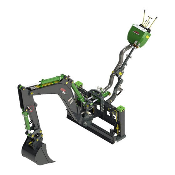
Page 13: Safety Labels And Main Components Of The Attachment
13 (46) 4.1 Safety labels and main components of the attachment Listed below are the labels and markings on the attachment. They must be visible and readable on the equipment. Replace any unclear or missing label. New labels are available via your retailer or contact information provided on the cover. - Page 14 14 (46) Table 4 - Backhoe 260 - Main components Frame with quick attach brackets Support bracket and locking device Lifting boom Front boom (stick) Controls, control valve Control valve boom & boom length adjustments Adjustable outriggers Boom swing cylinders...
-
Page 15: Attaching The Attachment
5. Attaching the attachment The backhoe 260 is delivered with a 400 mm bucket fitted and it is ready for use as delivered. When coupling the backhoe onto the loader, in addition to the quick coupling and connecting the hydraulic fittings, the supporting bracket (also called the top link) must also be mounted. - Page 16 16 (46) Step 4: After the locking pins are positively locked, lock the support bracket with locking device. Lift and tilt the backhoe so that hole support bracket aligns with the bracket on the loader boom. Lock the support bracket by turning the handle of the locking device.
-
Page 17: Connecting And Disconnecting Hydraulic Hoses
5.2 Connecting and disconnecting hydraulic hoses On Avant loaders the hydraulic hoses are connected using the multi connector system. If you have an Avant 300-700 series loader with the conventional quick couplers and wish to change to the multi connector system, contact your Avant dealer or service point for instructions or installation services. - Page 18 18 (46) To disconnect the multiconnector system: Before disconnecting put the attachment down on a solid and even surface. 1. Switch off the auxiliary hydraulics of the loader. 2. While pushing unlock button, turn the lever to disconnect the connector. 3.
-
Page 19: Uncoupling And Storage
19 (46) 5.3 Uncoupling and storage Uncouple and store the attachment on level ground. The best way to store the attachment is a place where it is protected from direct sunlight, rain, and extreme temperatures. Avoid leaving the attachment laying directly on the ground. Place it on blocks of wood or on a pallet, for example. -
Page 20: Using The Storage/Transport Support
20 (46) Correct storage position: Turn the backhoe to the position as shown in the figure below: Bucket flat on the ground, straight front, not too close to the frame Boom in such position that the storage supports can be locked ... -
Page 21: Transport Position
21 (46) 5.3.3 Transport position Turn the backhoe to its middle position (straight forward) so that it will not affect the stability of the loader. If driving with the backhoe attached over longer distances or at high speed, lower the control valve boom and turn it to the transport position. -
Page 22: Instructions For Use
22 (46) 6. Instructions for use Check the attachment and the operating environment once more before starting to work, and that all obstacles have been removed from the operating area. Quick inspection of the equipment and the operating area before use are parts of ensuring safety and the best performance of the equipment. -
Page 23: Checks Before Use
23 (46) 6.1 Checks before use Check that all obstacles, including any possibly hidden ones, have been removed from the working area or marked visibly before operation. Make sure that it safe to dig at the location. Find out if there are electric cables, water lines or similar ... -
Page 24: Outriggers
24 (46) 6.2.1 Outriggers The backhoe is equipped with hydraulic outriggers, which stabilise the backhoe during use and especially when moving material to the sides. Risk of tipping over - Keep outriggers on ground. For stability, the backhoe must be lowered on the ground and the outriggers must be firmly on the ground when operating the backhoe. -
Page 25: Controls
25 (46) 6.2.2 Controls Move the auxiliary hydraulics control lever to its locking position when ready to start operating the backhoe. Release the auxiliary hydraulics control lever whenever not operating the backhoe. The following label next to the controls describes the functions of the control levers. Replace damaged or missing label with a new one (A414016). - Page 26 26 (46) Left control joystick: Right control joystick: front boom (stick) main boom slewing bucket Switch on the left joystick: Bucket tilt adapter (optional equipment) Crushing hazard - Prevent unintentional movements of the attachment. Switch off the auxiliary hydraulics as soon as not using the backhoe to disable the controls of the backhoe.
- Page 27 27 (46) Planning and efficient use of the digging equipment Digging work is always started with thorough inspection of the site and planning the work in advance. Things to consider include at least the following: Inclinations and loader capabilities Digging movements and reach of the equipment ...
- Page 28 28 (46) The bucket should not be pressed too hard downwards, as it would cause the outriggers (and also the front tyres of the loader) to lift off the ground, pulling the loader towards the trench, and making digging ineffective. ...
-
Page 29: Operating On Inclined Terrain
29 (46) 6.3 Operating on inclined terrain Extra caution is needed when moving the equipment on inclined terrains and slopes. Drive slowly especially on inclined, uneven, or slippery surfaces, and avoid sudden changes in speed or direction. Operate the controls of the loader with careful and smooth movements. Watch out for ditches, holes on the ground, and other obstacles, as hitting an obstacle may cause the loader to tip over. - Page 30 30 (46) Table 5 - Backhoe 260 - Bucket options A414304 A35583 A414301 A35230 (standard bucket) Width: 250 mm 400 mm 750 mm 1000 mm Edge: 2 teeth 3 teeth straight straight Weight: 54 kg 66 kg 90 kg 130 kg...
-
Page 31: Installation Of Hydraulic Options
31 (46) 6.5 Installation of hydraulic options Pinching and crushing hazard - Make sure any part of attachment cannot move. Make sure the attachment is securely lowered on the WARNING ground. Shut down the loader engine and set the moving ... -
Page 32: Excavator Thumb (Optional Extra)
6.5.1 Excavator thumb (Optional extra) The Backhoe 260 can be equipped with an excavator thumb. The hydraulic excavator thumb makes it possible to handle irregural material such as rocks, concrete, branches, and debris that does not otherwise fit into the bucket. - Page 33 33 (46) Make sure that the slide bearings (3) are fixed to the mounting ends of the thumb (7). Slide the pivot pin (4) through the whole structure so that the boom, S30 quick coupling and bushings are fitted between the mounting ends of the thumb (7) as shown in the adjacent figure.
-
Page 34: Tilting Bucket Adapter (Optional Extra)
Tilting bucket adapter (Optional extra) The Backhoe 260 can be equipped with a tilting bucket adapter. With the tilting adapter, a grading bucket can be used to level the ground surface to desired slopes or, for example, to dig a ditch. The tilting adapter includes the same S30-150 quick coupling system for the bucket as the backhoe itself, so the same buckets can be used with the tilting system. - Page 35 35 (46) Table 6 – Tilt adapter components 1. S30 quick coupling for bucket 2. Upper frame, installed to the backhoe 3. Hydraulic quick couplings, 2 pcs 4. Tilting cylinder 5. Pivot pin 6.5.2.1 Installing tilt adapter The tilting bucket adapter is mounted between the front boom of the backhoe and the bucket. The tilting bucket adapter replaces the standard coupling, and is also equipped with S30-150 quick coupling for the bucket.
-
Page 36: Qualification Requirements For Installation Work
The manufacturer or it’s representative are not responsible for damages, losses or injuries resulted from incorrect or incomplete installations. Contact your nearest Avant dealer or service point, if you have any additional questions or require installation services. -
Page 37: Safety Instructions For Hydraulic Assemblies
37 (46) 6.5.4 Safety instructions for hydraulic assemblies High-pressure ejection of fluid may penetrate skin and cause serious injuries: Risk high pressure fluid injection through skin - High-pressure ejection of fluid may penetrate skin and cause serious DANGER injuries. Before handling hydraulic components, make sure that hydraulic... -
Page 38: Tightening Hydraulic Fittings
38 (46) 6.5.5 Tightening hydraulic fittings Tighten the fittings carefully according to given instructions and safety procedures. Keep in mind that over tightening will break a fitting. Tighten basic fittings carefully with hand tools using moderate torque. The elbow fittings should be tightened at last, after hoses have been fitted to their clamps. Allow the hydraulic systems of the loader and of the attachment to cool down completely before any work on hydraulic systems. - Page 39 39 (46) Risk of high pressure fluid injection through skin - Never test the tightness of the hydraulic components by placing hands near the fittings. Never tighten a pressurized hydraulic fitting, since the fitting may break and the released oil may cause DANGER serious injuries.
-
Page 40: Maintenance And Service
Finding any fault means that the hydraulic hose or component must be replaced and the equipment must not be used until it is repaired. Spare parts are available from your nearest AVANT retailer or authorised service point. Leave the repair work to professional service technicians, if you don’t have adequate knowledge and... -
Page 41: Cleaning The Attachment
41 (46) 7.2 Cleaning the attachment Clean the attachment regularly to prevent accumulation of dirt which is more difficult to remove. A pressure washer and mild detergent can be used for cleaning. Do not use strong solvents, and do not spray directly at the hydraulic components, or at the labels on the attachment. - Page 42 42 (46)
-
Page 43: Warranty Terms
43 (46) 8. Warranty terms Avant Tecno Oy grants a warranty of one year (12 months) from the date of purchase for the attachment it manufactures. The warranty covers repair costs as follows: Work costs are covered, if the repair is not performed at the factory. - Page 44 2006/42/EC as amended). The following harmonized standards have been applied: SFS-EN ISO 12100, SFS-EN ISO 4413 Mallit / Modeller / Models Avant Hydraulitoiminen kaivuulaite; Avant-kuormaajan työlaite Hydraulisk grävaggregat; arbetsredskap för Avant lastare A37510 Hydraulic backhoe; attachment for Avant loaders 26.9.2019 Ylöjärvi, Finland Risto Käkelä, Toimitusjohtaja / Verkställande direktör /...
Need help?
Do you have a question about the Backhoe 260 and is the answer not in the manual?
Questions and answers