
Related Manuals for Mircom RAM-208


Summary of Contents for Mircom RAM-208
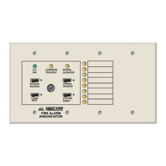
- Page 1 RAM-208 Remote Multiplex Annunciator Panel A.C. COMMON SIGNAL TROUBLE SILENCED BUZZER SIGNAL SILENCE SILENCE LAMP SYSTEM TEST RESET LT-648 Rev.8 Wiring & Installation Installation Manual February 2011...
-
Page 3: Table Of Contents
Table of Contents Table of Contents Introduction Contact Us ........................1.1.1 General Inquiries ......................1.1.2 Customer Service ......................1.1.3 Technical Support ......................1.1.4 Website ........................... Installation Instructions Controls & Displays ......................Wiring Instruction Dip Switch Settings Jumper Selection ......................Specifications & Features Enclosure ........................ - Page 4 Table of Contents 6.3.13 Security and Insurance ....................Limited Warranty ......................6.4.1 International Warranty ....................6.4.2 Conditions to Void Warranty ..................Warranty Procedure ....................... Disclaimer of Warranties ....................Out of Warranty Repairs ....................
- Page 5 List of Figures and Tables List of Figures and Tables Figure 1 Installation Diagram ......................Table 1 Controls and Displays ..................... Figure 2 Wiring Diagram ....................... Table 2 Maximum Wiring Run to Last Annunciator ..............Table 3 SW1 DIP Switch Settings ....................
- Page 6 List of Figures and Tables...
-
Page 7: Introduction
Introduction Introduction Mircom’s RAM-208 Annunciator is an 8-circuit annunciator for use with Mircom’s FA-200, FA- 300, FR-320, FX-350, FA-1000 and FX-2000. The annunciators mount into standard 4-gang electrical boxes, and may not be expanded. Control access is by a keyswitch. Each Circuit Indicator is a bi-colour LED that is automatically configured to match the Fire Alarm Control Panel configuration. -
Page 8: Contact Us
For General Inquiries, Customer Service and Technical Support you can contact us Monday to Friday 8:00 A.M. to 5:00 P.M. E.S.T. 1.1.1 General Inquiries Toll Free 1-888-660-4655 (North America Only) Local 905-660-4655 Email mail@mircom.com 1.1.2 Customer Service Toll Free 1-888-MIRCOM5 (North America Only) Local 905-695-3535 Toll Free Fax 1-888-660-4113 (North America Only) -
Page 9: Installation Instructions
Indicating and relay circuits are not remotely displayed. Refer to the manual of the fire alarm control panel that the annunciator will be connected to. The RAM-208 has a keyswitch to enable the four slide-switch controls. The key should be appropriately secured. -
Page 10: Wiring Instruction
FA Panel first Annunciator, then the next Annunciator, and so on. No star-wiring or T-tapping is allowed. Each RAM-208 Annunciator Module has a Figure 2 Wiring Diagram End-of-Line Resistor on its RS-485 Output terminals. This is removed on all except the last wired Module. -
Page 11: Dip Switch Settings
Dip Switch Settings Dip Switch Settings Each annunciator needs to be assigned a unique, sequential address via DIP switches SW1- 1, SW1-2, and SW1-3. DIP switch SW1-4 is used to allow disabling of some front panel slide switches. SW1-1 Address A0 Three digit address of the annunciator (address SW1-2 Address A1... -
Page 12: Specifications & Features
Specifications & Features Specifications & Features Enclosure A standard 4-gang Electrical Box is used. Electrical Specifications • 24 VDC nominal voltage • Slide-Switch Controls, LED indicators, and Keyswitch to enable Controls. • Local Buzzer, Indicators (AC-On, Common Trouble, Signal Silence), and Controls (System Reset, Lamp Test, Buzzer Silence, Signal Silence). -
Page 13: Warranty And Warning Information
Warranty and Warning Information Warranty and Warning Information Warning Please Read Carefully Note to End UsersThis equipment is subject to terms and conditions of sale as follows: Note to Installers This warning contains vital information. As the only individual in contact with system users, it is your responsibility to bring each item in this warning to the attention of the users of this system. -
Page 14: Compromise Of Radio Frequency (Wireless) Devices
Mircom shall not be liable for any delays, breakdowns, interruptions, loss, destruction, alteration or other problems in the use of a product arising our of, or caused by, the software. -
Page 15: Telephone Lines
During the warranty period, Mircom shall, at its option, repair or replace any defective product upon return of the product to its factory, at no charge for labor and materials. - Page 16 Mircom management, no credits will be issued for custom fabricated products or parts or for complete fire alarm system. Mircom will at its sole option, repair or replace parts under warranty. Advance replacements for such items must be purchased.
- Page 17 Products which Mircom determines to be repairable will be repaired and returned. A set fee which Mircom has predetermined and which may be revised from time to time, will be charged for each unit repaired.
- Page 20 CANADA - Main Office U.S.A TECHNICAL SUPPORT © Mircom 2011 25 Interchange Way 4575 Witmer Industrial Estates North America Printed in Canada Vaughan, ON L4K 5W3 Niagara Falls, NY 14305 Tel: (888) Mircom5 Subject to change without prior notice Tel: (888) 660-4655...
Need help?
Do you have a question about the RAM-208 and is the answer not in the manual?
Questions and answers