Table of Contents
Advertisement
Quick Links
STOP
READ ALL OF THE FOLLOWING INSTRUCTIONS BEFORE
REMOVING
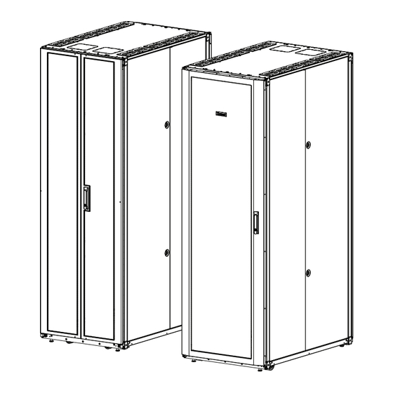
CM599H
CABINET
N
-A
S-Type Server Cabinets
ET
CCESS
TOOL LIST
-Phillips screwdriver
-Flatblade screwdriver
-22mm socket wrench
-15mm socket wrench
-13mm socket wrench
-8mm socket wrench
-48" level
FROM SKID
-7mm socket wrench
-T30 Torx bit
-T25 Torx bit
-6mm Allen key
-2.5mm Allen key
-Wire cutter
Advertisement
Table of Contents

Related Manuals for Panduit CM599H


Summary of Contents for Panduit CM599H
- Page 1 CM599H STOP READ ALL OF THE FOLLOWING INSTRUCTIONS BEFORE CABINET REMOVING FROM SKID S-Type Server Cabinets CCESS TOOL LIST -Phillips screwdriver -7mm socket wrench -T30 Torx bit -Flatblade screwdriver -22mm socket wrench -T25 Torx bit -15mm socket wrench -6mm Allen key -13mm socket wrench -2.5mm Allen key...
- Page 2 The recommended practices are based on average conditions. Panduit makes no representation or warranty, express or implied, nor assumes any responsibility for the accuracy or completeness of these installation instructions. Panduit does not guarantee any favorable results nor assume any liability for damages, improper installation, system failures, or any other problems that could arise in connection with the use of these installation instructions.
- Page 3 ANSI C2, the National Electrical Safety Code. The instruction shall not result in the risk of fire, electric shock, or injury to persons. UL Listing covers enclosure cabinet only For Technical Support: www.panduit.com/resources/install_maintain.asp Page 3 of 26...
-
Page 4: Table Of Contents
Cabinet Sealing…………………………………….………………………………... 22 Front and Back Floor Seals (for vertical exhaust ducts) ………………………… 23 Top of Cabinet Cable Manager Installation………………………………………… 24 Top of Cabinet Cable Manager Installation (for vertical exhaust ducts) ………… 25 For Technical Support: www.panduit.com/resources/install_maintain.asp Page 4 of 26... -
Page 5: Packaging Material Removal
(use 22mm socket wrench) Front Door Shipping Bracket [8] M10 Hex Head Screws (use 15mm socket wrench) [4] Shipping Hold Down Brackets Pallet Note: Doors, side panels, and other components are removed for clarity For Technical Support: www.panduit.com/resources/install_maintain.asp Page 5 of 26... -
Page 6: Leveling
(use 6mm Allen Key) Front-to-Back Cabinet Leveling Clockwise to RAISE cabinet Counter-clockwise to LOWER cabinet Side-to-Side Cabinet Leveling Note: When ganging multiple cabinets together, ensure that adjacent cabinets are adjusted to the same height. For Technical Support: www.panduit.com/resources/install_maintain.asp Page 6 of 26... -
Page 7: Floor Mounting
-1200mm deep cabinets: 878mm [34.57”] DIM B: DIM A -600mm wide cabinets: 191mm [7.52”] -700mm wide cabinets: 241mm [9.48”] -800mm wide cabinets: 291mm [11.46”] 4X 14mm DIA [0.55”] Floor Mounting View DIM B 2X 216mm [8.50”] For Technical Support: www.panduit.com/resources/install_maintain.asp Page 7 of 26... -
Page 8: Ganging
Ensure cabinets are level by following the guidelines on page 6. Leveling the cabinet prior to ganging is important to ensure proper door operation. [2] Front Ganging Brackets [4] M6 Torx Screws (use T25 Torx bit) FRONT OF CABINETS For Technical Support: www.panduit.com/resources/install_maintain.asp Page 8 of 26... - Page 9 Ensure cabinets are level by following the guidelines on page 6. Leveling the cabinet prior to ganging is important to ensure proper door operation. [2] Rear Ganging Brackets [4] M6 Torx Screws (use T25 Torx bit) REAR OF CABINETS For Technical Support: www.panduit.com/resources/install_maintain.asp Page 9 of 26...
-
Page 10: Grounding
Use [2] M5 bonding screws to fasten grounding terminal to cabinet frame (torque screws to 5.1 N-m (45 in-lb) Masking Tape [6] Grounding Lug Locations (Front and Rear of Beams) Masking Tape Note: top cap removed for clarity. For Technical Support: www.panduit.com/resources/install_maintain.asp Page 10 of 26... -
Page 11: Equipment Rail Adjustment
(use 15mm socket wrench) Slot of Front-to-Back Beam Equipment Rail Mount Nut (Finger Grip Area) Barbed Surface (face to outside of cabinet) TOP AND BOTTOM M10 Hex Head Screw (use 15mm socket wrench) For Technical Support: www.panduit.com/resources/install_maintain.asp Page 11 of 26... -
Page 12: Equipment Rails (Zero Ru Quicknet™ Patching Adapter Installation)
Equipment Rails (Zero RU QuickNet™ Patching Adapter Installation) • Insert plastic Patching Adapters by snapping adapter into rear-facing surface of rear equipment rails. • Patching Adapters accommodate Panduit QuickNet™ Copper and Fiber Cabling Systems (optional) • Included on select 600mm wide S-Type cabinet configurations Insert Patching Adapters (snap into equipment rails) For Technical Support: www.panduit.com/resources/install_maintain.asp... -
Page 13: Overhead Cable Openings
[6] M10 Threaded Holes Removable Insert OPTIONAL use wire cutters to remove sheet metal blanks. Overhead Cable Opening Bezel Bezel [2] 165.1mm x 165.1mm Openings [6.5” x 6.5”] For Technical Support: www.panduit.com/resources/install_maintain.asp Page 13 of 26... -
Page 14: Cable Management Fingers Installation (Sn15F, Sn25F)
Insert tabs of Cable Management Finger into mounting slots of cabinet post • Slide Cable Management Finger inward to lock into place Cable Managment Finger -Insert tabs into cabinet post -Slide inward to lock in place For Technical Support: www.panduit.com/resources/install_maintain.asp Page 14 of 26... -
Page 15: Single Hinge Door (Removal And Installation)
VIEW 2 Lift bottom of door off Bottom Hinge Pin • REVERSE STEPS to install Single Hinge Door Top Hinge Screw Compression Sleeve (Pull down) VIEW 1 VIEW 2 VIEW 3 Bottom Hinge Pin For Technical Support: www.panduit.com/resources/install_maintain.asp Page 15 of 26... - Page 16 Loosen Cam Screw to reposition Door Cam and Cam Stop to outside of door. Tighten Cam Screw • With Door Handle repositioned, secure Door Handle Backing Plate to Door Handle • Remove PANDUIT label and re-attach in correct orientation near top of door • Reinstall Single Hinge Door per instructions on Page 15 VIEW 3...
-
Page 17: Rear Split Doors (Removal And Installation)
Rear Split Doors (Removal and Installation) • Open Rear Split Doors to approximately 90º • Lift Rear Split Doors up pull doors away from cabinet frame • REVERSE STEPS to install Rear Split Doors For Technical Support: www.panduit.com/resources/install_maintain.asp Page 17 of 26... -
Page 18: Side Panels (Distinguishing Features)
(outside) (inside) ORIGINAL VERSION CURRENT VERSION No backstop feature Backstop feature on bottom beam on bottom beam ORIGINAL VERSION CURRENT VERSION [2] Plastic [2] Adjustable bushings bushings For Technical Support: www.panduit.com/resources/install_maintain.asp Page 18 of 26... -
Page 19: Side Panels (Removal/Installation And Adjustment - Optional)
Rear Side Panel Front Side Panel Adjustment Bushing Adjust Fit of Side Panels Adjustment Use included wrench to raise Side panels removed Wrench or lower adjustment bushings from view to add clarity (included) For Technical Support: www.panduit.com/resources/install_maintain.asp Page 19 of 26... -
Page 20: Pdu Bracket Adjustment
Secure each PDU bracket to cabinet post with [2] M5 Torx Screws per bracket Top PDU Bracket [2] M5 Torx Screws (use T25 Torx bit) PDU Bracket (installed) Bottom PDU Bracket [2] M5 Torx Screws (use T25 Torx bit) For Technical Support: www.panduit.com/resources/install_maintain.asp Page 20 of 26... -
Page 21: Cable Management/Pdu Bracket Adjustment
M5 Torx Screws -Use T25 Torx driver Primary Mounting Hole Alternate Mounting Holes Alternate mounting holes are to be used NOTE: when installing 70”+ PDUs on Cable Man- agement/PDU Bracket in 42 RU cabinets For Technical Support: www.panduit.com/resources/install_maintain.asp Page 21 of 26... -
Page 22: Cabinet Sealing
Install [2] foam seals to the upper and lower frame. Seal should be pressed up against the Equipment Rails, behind the latch plugs. [3] Latch Plugs Foam Seal Foam Seal [3] Latch Plugs For Technical Support: www.panduit.com/resources/install_maintain.asp Page 22 of 26... -
Page 23: Front And Back Floor Seals (For Vertical Exhaust Ducts)
Install Floor Seal to front or rear of cabinet frame using (2) M10x20mm Bolts. (Flange on floor seal will face outward away from the cabinet.) [2] M10x20mm Bolts (use 15mm socket wrench) Floor Seal For Technical Support: www.panduit.com/resources/install_maintain.asp Page 23 of 26... -
Page 24: Top Of Cabinet Cable Manager Installation
[4] M5 Torx Screws (use T25 Torx bit) [5] M5 Torx Screws Rear Fascia (use T25 Torx bit) Front Fascia [2] Vertical Walls [4] M5 Torx Screws (use T25 Torx bit) Studs For Technical Support: www.panduit.com/resources/install_maintain.asp Page 24 of 26... -
Page 25: Top Of Cabinet Cable Manager Installation (For Vertical Exhaust Ducts)
[4] M5 Torx Screws (use T25 Torx bit) Rear Vertical Wall Studs IMPORTANT VERTICAL EXHAUST DUCT MUST BE INSTALLED PRIOR TO INSTALLATION OF REAR VERTICAL WALL [4] M5 Torx Screws (use T25 Torx bit) For Technical Support: www.panduit.com/resources/install_maintain.asp Page 25 of 26... - Page 26 INSTALLATION INSTRUCTIONS CM599H THIS PAGE IS INTENTIONALLY BLANK For Instructions in Local Languages E-mail: and Technical Support: techsupport@panduit.com Phone: www.panduit.com/resources/install_maintain.asp 866-405-6654 www.panduit.com Page 26 of 26...
Need help?
Do you have a question about the CM599H and is the answer not in the manual?
Questions and answers