Table of Contents
Advertisement
Available languages
Available languages
Advertisement
Table of Contents

Subscribe to Our Youtube Channel
Related Manuals for FS IMC-1S1XMG


Summary of Contents for FS IMC-1S1XMG
- Page 1 P2 Fault 10G SFP+ 10GBASE-T 2.5G 10G/1G 5G/100 IMC-1S1XMG INDUSTRIAL ETHERNET MEDIA CONVERTERS INDUSTRIELLE ETHERNET-MEDIENKONVERTER CONVERTISSEURS DE MÉDIAS ETHERNET INDUSTRIELS Quick Start Guide V1.0 Quick-Start Anleitung Guide de Démarrage Rapide...
- Page 2 P1 P2 Alarm P2 Fault 100/1G /2.5G LNK/ 2.5G 1000 10G SFP+ 100/1G /2.5G LNK/ 10/100 /1000T 10GBASE-T 2.5G 10G/1G 10/100 LNK/ACT 1000 LNK/ACT 5G/100 IMC-1S1XMG IMC-2M2T IMC-1S1XMG IMC-2M2T Accessories IMC-1S1XMG Mounting Bracket x2 Dust Cap x1 Screw x4...
-
Page 3: Hardware Overview
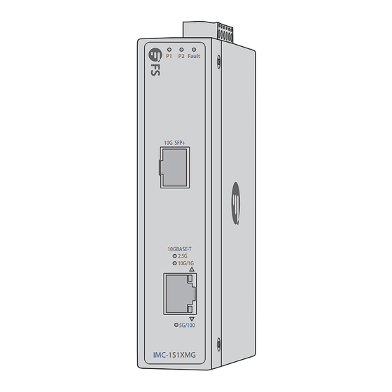
IMC-2M2T Mounting Bracket x2 Dust Cap x2 Screw x4 Hardware Overview Front Panel Ports IMC-1S1XMG P2 Fault 10G SFP+ SFP+ 10GBASE-T 2.5G 10G/1G RJ45 5G/100 IMC-1S1XMG Ports Description SFP+ SFP+ ports for 10G fiber connection 100M/1G/2.5G/5G/10GBase-T ports for Ethernet RJ45... -
Page 4: Front Panel Leds
1000 100/1G /2.5G LNK/ 10/100 /1000T RJ45 10/100 LNK/ACT 1000 LNK/ACT IMC-2M2T Ports Description SFP ports for 100M/1G/2.5GBase-X fiber connection RJ45 10/100/1000Base-T ports for Ethernet connection Front Panel LEDs IMC-1S1XMG P2 Fault 10G SFP+ 10GBASE-T 2.5G 10G/1G RJ45 5G/100 IMC-1S1XMG... -
Page 5: State Description
LEDs State Description Power 1 is on. Green Power 1 is off. Off Power 2 is on. Green Power 2 is off. Off Either Power 1 or Power 2 fails. Fault No failure. Off The copper port is operating at Green 2.5Gbps. - Page 6 LEDs State Description Green Power 1 is on. Green Power 2 is on. Alarm The alarm LED is triggered. The link through that port is successfully Orange established at 10/100Mbps. 10/100 LNK/ACT The converter is sending or receiving Blinking data over that port. Orange The link through that port is successfully Green...
-
Page 7: Upper Panel
Upper Panel IMC-1S1XMG Max. fault loading: 24V, 1A 1 2 3 4 5 6 V1+ V1- V2+ V2- DC Input: 12-48V , 0.6A max. AC Input: 24V~, 0.2A max. PWR1 Fault PWR2 Grounding Point Terminal Block Connector Fault Alarm Contacts IMC-2M2T Max. -
Page 8: Back Panel
3. If the Redundant Mode is used, one of the two fiber ports will be redundant while the other 1 or 2 copper ports are in operation. Back Panel IMC-1S1XMG/IMC-2M2T DIN Rail Mounting Kit Installation Requirements Before the installation, make sure that you have the following conditions ready: Phillips screwdriver. -
Page 9: Site Environment
Site Environment: Ensure that the operating temperature is maintained at -40°C~75°C and the humidity at 5%~95%. Do not install the equipment in a dusty environment. The installation site must be free from leaking or dripping water, heavy dew, and humidity. The installation site should be well-ventilated. - Page 10 2. Press the converter down to clamp the lower end of the mounting kit to the track. Shake the converter slightly to check if it is tightly secured. 3. If you need to remove the converter, lightly pull the lower end of the mounting kit out of the track, and lift the converter up to remove it from the track.
-
Page 11: Wall Mounting
Wall Mounting 1. Remove the DIN rail mounting kit from the converter. NOTE: Please keep the accessories properly after removal in case of need. 2. Secure mounting brackets to the back panel of the converter using the supplied screws. M a x . fa u lt lo a d in g : 2 4 V , 1 A... -
Page 12: Side Wall Mounting
3. Drill four right-sized holes in the wall. Knock wall plugs into the holes. 4. Align the holes with expansion bolts and insert the bolts. 5. Adjust the position of the converter and tighten the expansion bolts. NOTE: The expansion bolts and related accessories are purchased separately. - Page 13 IMC-2M2T also supports side wall mounting, and the procedures are similar to the wall installation. Please follow the pictures. Grounding the Converter Max. fault loading: 24V, 1A 1 2 3 4 5 6 V1+ V1- V2+ V2- DC Input: 12-48V , 0.6A max.
- Page 14 CAUTION: The device MUST be grounded. EMD (Lightning) damage is not covered under the warranty. NOTE: The grounding cable is not included in the accessories. Connecting the RJ45 Port CO N M a x . fa u lt lo a d in g : 2 4 V , 1 A MG MT...
- Page 15 Connecting the SFP+/SFP Port M a x M a x . f a u l t l o a d i n g : 2 4 V , 1 V 1 + V V 1 + V V 2 + V P W R 1 P W R F a u l t...
-
Page 16: Connecting The Power
Remove the Optical Module x . f a u l t l o a d i n g : 2 4 V , 1 A V 1 - V 2 + V F a u l t P W R 2 D C I n p u t : 1 2 - 4 8 V... - Page 17 Max. fault loading: 24V, 1A 1 2 3 4 5 6 V1+ V1- V2+ V2- DC Input: 12-48V , 0.6A max. AC Input: 24V~, 0.2A max. PWR1 Fault PWR2 Name Description V1+, V2+ Live line/positive V1-, V2- Null line/negative Fault alarm contacts NOTE: 1.
-
Page 18: Troubleshooting
NOTE: 1. The wire gauge for the terminal block connector should be in the range of 12 to 24 AWG. 2. The DC power input range is 12V to 48V DC and supports 24V 3. Use a single input when using the 24V AC power. Troubleshooting Port LEDs Are Not Lit Check the cable connection of the media converter. -
Page 19: Online Resources
Product Warranty FS ensures our customers that for any damage or faulty items due to our workmanship, we will offer a free return within 30 days from the day you receive your goods. This excludes any custom-made items or tailored solutions. - Page 20 Ihrem Netzwerk einsetzen. P1 P2 Alarm P2 Fault 100/1G /2.5G LNK/ 2.5G 1000 10G SFP+ 100/1G /2.5G LNK/ 10/100 /1000T 10GBASE-T 2.5G 10G/1G 10/100 LNK/ACT 1000 LNK/ACT 5G/100 IMC-1S1XMG IMC-2M2T IMC-1S1XMG IMC-2M2T Zubehör IMC-1S1XMG Montage-Halterung x2 Staubkappe x1 Schraube x4...
- Page 21 IMC-2M2T Montage-Halterung x2 Staupkappe x2 Schraube x4 Hardware-Übersicht Ports an der Vorderseite IMC-1S1XMG P2 Fault 10G SFP+ SFP+ 10GBASE-T 2.5G 10G/1G RJ45 5G/100 IMC-1S1XMG Port Beschreibung SFP+ SFP+-Ports für 10G-Glasfaseranschluss 100M/1G/2,5G/5G/10GBase-T-Ports für Ethernet- RJ45 Verbindungen...
-
Page 22: Leds An Der Vorderseite
100/1G /2.5G LNK/ 2.5G 1000 100/1G /2.5G LNK/ 10/100 /1000T RJ45 10/100 LNK/ACT 1000 LNK/ACT IMC-2M2T Port Beschreibung SFP-Ports für 100M/1G/2.5GBase-X Glasfaseranschluss RJ45 10/100/1000Base-T-Ports für Ethernet-Verbindungen LEDs an der Vorderseite IMC-1S1XMG P2 Fault 10G SFP+ 10GBASE-T 2.5G 10G/1G RJ45 5G/100 IMC-1S1XMG... - Page 23 State Description Power 1 ist eingeschaltet. Grün Power 1 ist ausgeschaltet. Power 2 ist eingeschaltet. Grün Power 2 ist ausgeschaltet. Entweder fällt Power 1 oder Power 2 aus. Störung Keine Störung. Grün Der Kupferport arbeitet mit 2,5 Gbit/s. 10/2.5/1G Orange Der Kupferport arbeitet mit 10/1Gbit/s.
- Page 24 Status Beschreibung Grün Power 1 ist eingeschaltet. Grün Power 2 ist eingeschaltet. Alarm Die Alarm-LED wird ausgelöst. Die Verbindung über diesen Port wird Orange erfolgreich mit 10/100Mbps hergestellt. 10/100 LNK/ACT Der Konverter sendet oder empfängt Blinkt Daten über diesen Port. Orange Die Verbindung über diesen Port wird Grün...
- Page 25 Oberes Panel IMC-1S1XMG Max. fault loading: 24V, 1A 1 2 3 4 5 6 V1+ V1- V2+ V2- DC Input: 12-48V , 0.6A max. AC Input: 24V~, 0.2A max. PWR1 Fault PWR2 Erdungspunkt Klemmenblock-Anschluss Fehlermeldekontakte IMC-2M2T Max. Fault Alarm Loading: 24V, 1A DC Input: 12-48V , 0.6A...
- Page 26 3. Wenn der Redundanzmodus verwendet wird, ist einer der beiden Glasfaseranschlüsse redundant, während die anderen 1 oder 2 Kupferports in Betrieb sind. Hinteres Panel IMC-1S1XMG/IMC-2M2T DIN-Schienen-Montagesatz Installationvoraussetzungen Vergewissern Sie sich vor der Installation, dass Sie die folgenden Voraussetzungen erfüllt haben: Kreuzschlitzschraubendreher.
- Page 27 Standortumgebung: Stellen Sie sicher, dass die Betriebstemperatur bei -40°C~75°C und die Luftfeuchtigkeit bei 5%~95% gehalten wird. Installieren Sie das Gerät nicht in einer staubigen Umgebung. Der Aufstellungsort muss frei von austretendem oder tropfendem Wasser, starkem Tau und Feuchtigkeit sein. Der Aufstellungsort sollte gut belüftet sein. Stellen Sie sicher, dass der Konverter eben und stabil ist, um gefährliche Bedingungen zu vermeiden.
- Page 28 2. Drücken Sie den Konverter nach unten, um das untere Ende des Montagesatzes an die Schiene zu klemmen. Schütteln Sie den Konverter leicht, um zu prüfen, ob er fest sitzt. 3. Wenn Sie den Koknverter entfernen müssen, ziehen Sie das untere Ende des Montagesatzes leicht aus der Schiene und heben Sie den Konverter an, um ihn aus der Schiene zu entfernen.
- Page 29 Wandmontage 1. Nehmen Sie den DIN-Schienen-Montagesatz vom Konverter ab. HINWEIS: Bitte bewahren Sie das Zubehör nach dem Entfernen für den Fall auf, dass es benötigt wird. 2. Befestigen Sie die Halterungen mit den mitgelieferten Schrauben an der Rückwand des Konverters. M a x .
- Page 30 3. Bohren Sie vier Löcher in der richtigen Größe in die Wand. Schlagen Sie Dübel in die Löcher. 4. Richten Sie die Löcher mit den Dehnungschrauben aus und setzen Sie die Schrauben ein. 5. Passen Sie die Position des Konverters an und ziehen Sie die Dehnungsschrauben fest.
- Page 31 Der IMC-2M2T kann auch seitlich an der Wand montiert werden. Die Verfahren sind ähnlich wie bei der Wandmontage. Bitte folgen Sie den Bildern. Erdung des Konverters Max. fault loading: 24V, 1A 1 2 3 4 5 6 V1+ V1- V2+ V2- DC Input: 12-48V , 0.6A max.
- Page 32 ACHTUNG: Das Gerät MUSS geerdet werden. EMD-Schäden (Blitzschlag) sind nicht durch die Garantie abgedeckt. HINWEIS: Das Erdungskabel ist nicht im Zubehör enthalten. Anschließen des RJ45-Port CO N M a x . fa u lt lo a d in g : 2 4 V , 1 A MG MT S5 85 0- 24 XM...
- Page 33 Anschließen des SFP+/SFP-Ports M a x M a x . f a u l t l o a d i n g : 2 4 V , 1 V 1 + V V 1 + V V 2 + V P W R 1 P W R F a u l t...
-
Page 34: Anschließen Der Stromversorgung
Entfernen des optischen Moduls x . f a u l t l o a d i n g : 2 4 V , 1 A V 1 - V 2 + V F a u l t P W R 2 D C I n p u t : 1 2 - 4 8 V... - Page 35 Max. fault loading: 24V, 1A 1 2 3 4 5 6 V1+ V1- V2+ V2- DC Input: 12-48V , 0.6A max. AC Input: 24V~, 0.2A max. PWR1 Fault PWR2 Name Beschreibung V1+, V2+ Stromführender Lleiter/positiv V1-, V2- Nullleiter/negativ Erfordert eine gute Erdung HINWEIS: 1.
-
Page 36: Fehlersuche
HINWEIS: 1. Der Drahtquerschnitt für den Anschluss der Klemmleiste sollte im Bereich von 12 bis 24 AWG liegen. 2. Der DC-Eingangsbereich beträgt 12 bis 48V DC und unterstützt 24V AC. 3. Verwenden Sie einen einzelnen Eingang, wenn Sie 24V Wechselstrom verwenden. Fehlersuche Die Port-LEDs leuchten nicht Überprüfen Sie die Kabelverbindung des Medienkonverters. - Page 37 Kontakt https://www.fs.com/de/contact_us.html Produktgarantie FS garantiert seinen Kunden, dass wir im Falle von Schäden oder fehlerhaften Artikeln, die auf unsere Verarbeitung zurückzuführen sind, eine kostenlose Rückgabe innerhalb von 30 Tagen nach Erhalt der Ware anbieten. Dies gilt nicht für Sonderanfertigungen oder maßgeschneiderte Lösungen.
- Page 38 P1 P2 Alarm P2 Fault 100/1G /2.5G LNK/ 2.5G 1000 10G SFP+ 100/1G /2.5G LNK/ 10/100 /1000T 10GBASE-T 2.5G 10G/1G 10/100 LNK/ACT 1000 LNK/ACT 5G/100 IMC-1S1XMG IMC-2M2T IMC-1S1XMG IMC-2M2T Accessoires IMC-1S1XMG Support de Montage x2 Capuchon Anti-poussière x1 Vis x4...
-
Page 39: Aperçu Du Matériel
IMC-2M2T Support de Montage x2 Capuchon Anti-poussière x2 Vis x4 Aperçu du Matériel Ports du Panneau Frontal IMC-1S1XMG P2 Fault 10G SFP+ SFP+ 10GBASE-T 2.5G 10G/1G RJ45 5G/100 IMC-1S1XMG Ports Description SFP+ Ports SFP+ pour une connexion fibre 10G Ports 100M/1G/2.5G/5G/10GBase-T pour connexion... - Page 40 LNK/ 10/100 /1000T RJ45 10/100 LNK/ACT 1000 LNK/ACT IMC-2M2T Ports Description Ports SFP pour connexion fibre 100M/1G/2.5GBase-X RJ45 Ports 10/100/1000Base-T pour la connexion Ethernet Indicateurs LED du Panneau Frontal IMC-1S1XMG P2 Fault 10G SFP+ 10GBASE-T 2.5G 10G/1G RJ45 5G/100 IMC-1S1XMG...
- Page 41 Statut Description L'alimentation 1 est en marche. Vert L'alimentation 1 est éteinte. Éteint L'alimentation 2 est en marche. Vert L'alimentation 2 est éteint. Éteint L'alimentation 1 ou l'alimentation 2 est Rouge en panne. Fault Aucune défaillance. Éteint Vert Le port cuivre fonctionne à 2.5Gbps. 10/2.5/1G Orange Le port cuivre fonctionne à...
- Page 42 Statut Description Vert L'alimentation 1 est en marche. Vert L'alimentation 2 est en marche. Alarm L'indicateur de l'alarme est déclenché. La liaison par ce port est établie avec Orange succès à 10/100Mbps. 10/100 LNK/ACT Le convertisseur envoie ou reçoit des Orange données sur ce port.
-
Page 43: Panneau Supérieur
Panneau Supérieur IMC-1S1XMG Max. fault loading: 24V, 1A 1 2 3 4 5 6 V1+ V1- V2+ V2- DC Input: 12-48V , 0.6A max. AC Input: 24V~, 0.2A max. PWR1 Fault PWR2 Point de Mise à la Terre Connecteur du Bornier Contacts d'Alarme de Défaut... -
Page 44: Panneau Arrière
3. Si le mode redondant est utilisé, l'un des deux ports fibre sera redondant alors que les 1 ou 2 autres ports cuivre sont en fonctionnement. Panneau Arrière IMC-1S1XMG/IMC-2M2T Kit de Montage sur Rail DIN Exigences d'Installation Avant de procéder à l'installation, assurez-vous de disposer des éléments suivants :... - Page 45 Site de l'Installation : Assurez-vous que la température de fonctionnement est maintenue à -40°C~75°C et l'humidité à 5%~95%. Ne pas installer l'équipement dans un environnement poussiéreux. Le site d'installation doit être exempt de fuites d'eau et d'humidité. Le site d'installation doit être bien ventilé. Assurez-vous que le convertisseur est à...
- Page 46 2. Appuyez sur le convertisseur vers le bas pour fixer l'extrémité inférieure du kit de montage sur le rail. Secouez légèrement le convertisseur pour vérifier qu'il est bien fixé. 3. Si vous devez retirer le convertisseur, tirez légèrement l'extrémité inférieure du kit de montage hors du rail, et soulevez le convertisseur pour le retirer.
-
Page 47: Installation Murale
Installation Murale 1. Retirez le kit de montage sur rail DIN du convertisseur. NOTE : Veuillez conserver correctement les accessoires après leur retrait en cas de besoin. 2. Fixez les supports de montage au panneau arrière du convertisseur à l'aide des vis fournies. M a x . - Page 48 3. Percez quatre trous de taille correcte dans le mur. Enfoncez les chevilles dans les trous. 4. Alignez les trous avec les boulons d'expansion et insérez les boulons. 5. Ajustez la position du convertisseur et serrez les boulons d'expansion. NOTE : Les boulons d'expansion et les accessoires connexes sont achetés séparément.
- Page 49 L'IMC-2M2T peut également être installé sur une paroi latérale, et les procédures sont similaires à celles de l'installation murale. Veuillez suivre les photos. Mise à la Terre du Convertisseur Max. fault loading: 24V, 1A 1 2 3 4 5 6 V1+ V1- V2+ V2- DC Input: 12-48V...
- Page 50 ATTENTION : L'appareil DOIT être mis à la terre. Les dommages causés par les EMD (foudre) ne sont pas couverts par la garantie. NOTE : Le câble de mise à la terre n'est pas inclus dans les accessoires. Connexion au Port RJ45 CO N M a x .
- Page 51 Connexion au Port SFP+/SFP M a x M a x . f a u l t l o a d i n g : 2 4 V , 1 V 1 + V V 1 + V V 2 + V P W R 1 P W R F a u l t...
-
Page 52: Connexion De L'alimentation
Retirer le Module Optique x . f a u l t l o a d i n g : 2 4 V , 1 A V 1 - V 2 + V F a u l t P W R 2 D C I n p u t : 1 2 - 4 8 V... - Page 53 Max. fault loading: 24V, 1A 1 2 3 4 5 6 V1+ V1- V2+ V2- DC Input: 12-48V , 0.6A max. AC Input: 24V~, 0.2A max. PWR1 Fault PWR2 Nomination Description V1+, V2+ Ligne directe/positive V1-, V2- Ligne nulle/négative Requiert une bonne connexion à la terre NOTE : 1.
-
Page 54: Dépannage
NOTE : 1. Le calibre du fil pour le connecteur du bornier doit être de 12 à 24AWG. 2. La plage d'entrée de l'alimentation DC est de 12 à 48V DC et prend en charge 24V AC. 3. Utilisez une seule entrée lorsque vous utilisez l'alimentation 24V AC. -
Page 55: Ressources En Ligne
Garantie du Produit FS garantit à ses clients que tout article endommagé ou défectueux dû à sa fabrication pourra être retourné gratuitement dans un délai de 30 jours à compter de la date de réception de la marchandise. Ceci exclut les articles faits sur mesure ou les solutions personnalisées.
Need help?
Do you have a question about the IMC-1S1XMG and is the answer not in the manual?
Questions and answers