FS UMC-GA1F1T Quick Start Manual
Unmanaged ethernet media converters
Hide thumbs
Also See for UMC-GA1F1T:
- Quick start manual (70 pages) ,
- Quick start manual (93 pages) ,
- Quick start manual (86 pages)
Table of Contents
Advertisement
Available languages
Available languages
Quick Links
Advertisement
Table of Contents

Related Manuals for FS UMC-GA1F1T


Summary of Contents for FS UMC-GA1F1T
- Page 1 UNMANAGED ETHERNET MEDIA CONVERTERS UNMANAGED ETHERNET-MEDIENKONVERTER CONVERTISSEUR DE MÉDIA ETHERNET NON GÉRÉ アンマネージドイーサネット・メディアコンバーター Quick Start Guide V7.0 Quick-Start Anleitung Guide de Démarrage Rapide クイックスタートガイド...
- Page 2 Introduction Thank you for choosing Unmanaged Ethernet Media Converters. This guide is designed to familiarize you with the layout of the media converters and describe how to deploy them in your network. UMC-GA1F1T UMC-GA1F2T UMC-GA1SC1T-MM...
- Page 3 UMC-GA1SC1T-SM UMC-1S1T-R...
- Page 4 Accessory Power Adapter x1 NOTE: The power adapter will be packed according to the plug standard of di erent regions. This picture is for reference only. Please refer to the product received.
-
Page 5: Hardware Overview
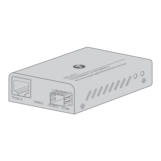
Hardware Overview Front Panel Ports UMC-GA1F1T RJ45 Port SFP Port UMC-GA1F2T RJ45 Port SFP Port Ports Description 10/100/1000Base-T RJ45 port for Ethernet connection RJ45 Hot-swappable SFP port for 1G ber connection UMC-GA1SC1T-MM/UMC-GA1SC1T-SM RJ45 Port SC Port... - Page 6 SC port for duplex SC single mode or multimode ber connection UMC-1S1T-R RJ45 Port SFP+ Port Ports Description 100M/1G/2.5G/5G/10GBase-T RJ45 port for RJ45 Ethernet connection SFP+ Hot swappable SFP+ port for 10G ber connection Front Panel LEDs UMC-GA1F1T TP/LNK 1000M FX/LNK PWR...
- Page 7 LEDs State Description Link through the copper port is Green successfully established, but no data transmission. TP/LNK The copper port is actively sending or Blinking receiving data. Green The copper port is linked down. The copper port is operating at Green 1000M.
- Page 8 LEDs State Description Green TP1 port is operating at 1000M. TP1 port is operating at 100M. TP1/LNK Dual TP1 port is operating at 10M. Color TP2 port is operating at 1000M. Green TP2 port is operating at 100M. TP2/LNK Dual TP2 port is operating at 10M.
- Page 9 LEDs State Description The link through the TP port is Green successfully established. TP/LNK Blinking The TP port is actively sending or Green receiving data. The TP port link is down. Green The TP port is operating at 1000M. The TP port is operating at 10M/100M. The link through the ber port is Green successfully established.
- Page 10 LEDs State Description Green The optical port is connected. FX/LNK The optical port is not connected. Green The device is working properly. The device is not working. Bottom Panel UMC-GA1F1T UMC-GA1SC1T-MM/UMC-GA1SC1T-SM...
- Page 11 Function State Description Disable LFP Function Enable Disable ALS Function Enable Disable FX Reset Enable FX 1000M FX Speed Set FX 100M/1000M UMC-GA1F2T Function State Description Reserved Normal (Up to 1500Bytes) Jumbo Frame Up to 9KB Disable Port Isolation Enable FX 1000M FX Speed Set FX 100M...
- Page 12 UMC-1S1T-R Function State Description Disable LFP Function Enable Disable ALS Function Enable 1: TP=10G, FX=10G. 2: TP=10M/100M/ Media 1000M,FX=1G Converter TP=10M/100M/ Model* 1000M/10G, FX=10G...
-
Page 13: Installation Requirement
VLAN. Installation Requirement Do not operate it in an area that exceeds an ambient temperature of 40°C for UMC-GA1F1T/UMC-GA1F2T or 50°C for UMC-GA1SC1T-MM/UMC-GA1SC1T-SM/UMC-151T-R. The installation site should be well-ventilated. Be sure that the media converter is level and stable to avoid any hazardous conditions. -
Page 14: Mounting The Converter
Mounting the Converter Desk Mounting Place the converter on a at and secure desk. Rack Mounting (With MFMC-12DP Mini Media Converter Chassis) - Page 15 1. Install the mounting brackets on the left rear side and the right rear side of the converter with one M3 screw respectively. NOTE: Please purchase the MFMC-12DP 12 Slots Mini Media Converter Chassis on fs.com...
- Page 16 2. Install the media converters onto the chassis in sequence from the lower to the upper. Fix each converter tightly in the chassis by two M3 screws (not included). 3. Place the chassis into the rack. Align the brackets of the chassis to the side holes on the rack and secure the chassis to the rack with M4 screws and cage nuts (not included).
- Page 17 Cat 6a/7 cable is required for 10G and Cat 6 cable for 1000M. Make sure that the converter supports the corresponding rate. 2. Connect the other end of the network cable to the network device, switch, PC, router, etc. Connecting to the SFP Port For UMC-GA1F1T/UMC-GA1F2T...
- Page 18 1. Insert an SFP transceiver into the SFP port. 2. Connect a ber optic cable to the transceiver. Plug the other end of the ber optic cable into the ber network. NOTE: Both multimode and single mode cablings are supported. Make sure both sides of the transceiver are with the same media type.
- Page 19 Connecting the SC Port For UMC-GA1SC1T-MM/UMC-GA1SC1T-SM Connect one end of a ber optic cable to the SC port and the other end to the ber network. TX and RX must be paired at both ends. NOTE: The media converter is installed with the SC port by default.
- Page 20 Connecting the Power Desk Mounting: Connect one end of the power adapter to the converter and the other end to the power source. Then verify that the power LED lights up. Rack Mounting: Connect the chassis power cord to the chassis and turn on the power switch on the back of the chassis.
-
Page 21: Troubleshooting
Troubleshooting The per Port LED Is Not Lit Check the cable connection of the converter. Performance Is Bad Check the speed duplex mode of the partner device. The converter usually runs in auto-negotiation mode. If the partner is set to half duplex, the performance will be poor. Per Port LED Is Lit, but the Tra c Is Irregular Check that the attached device is not set to dedicate full duplex. -
Page 22: Product Warranty
Product Warranty FS ensures our customers that for any damage or faulty items due to our workmanship, we will o er a free return within 30 days from the day you receive your goods. This excludes any custom-made items or tailored solutions. - Page 23 Download the FS App Scan the QR code to download and install the FS app from the App Store or Google Play Store or go to https://www.fs.com/appdownload.html...
- Page 24 Einführung Vielen Dank, dass Sie sich für die Unmanaged Ethernet- Medienkonverter entschieden haben. Diese Anleitung soll Sie mit dem Aufbau der Medienkonverter vertraut machen und beschreiben, wie Sie sie in Ihrem Netzwerk einsetzen können. UMC-GA1F1T UMC-GA1F2T...
- Page 25 UMC-GA1SC1T-MM UMC-GA1SC1T-SM UMC-1S1T-R...
- Page 26 Zubehör Netzadapter x1 HINWEIS: Der Netzadapter wird entsprechend dem Steckerstandard der verschiedenen Regionen geliefert. Dieses Bild gilt nur als Referenz. Bitte beziehen Sie sich auf das erhaltene Produkt.
- Page 27 Hardware-Übersicht Ports an der Vorderseite UMC-GA1F1T RJ45-Port SFP-Port UMC-GA1F2T RJ45-Port SFP-Port Ports Beschreibung 10/100/1000Base-T RJ45-Port für die Ethernet- RJ45 Verbindung. Hot-Swap-fähiger SFP-Port für die 1G- Glasfaserverbindung. UMC-GA1SC1T-MM/UMC-GA1SC1T-SM RJ45-Port SC-Port...
- Page 28 RJ45 Ethernet-Verbindung SC-Port für den Anschluss an Duplex-SC- Singlemode oder Multimode-Glasfaser. UMC-1S1T-R RJ45 Port SFP+ Port Ports Beschreibung 100M/1G/2,5G/5G/10GBase-T RJ45-Port für RJ45 die Ethernet-Verbindung Hot-Swap-fähiger SFP+-Port für die 10G- SFP+ Glasfaserverbindung LEDs an der Vorderseite UMC-GA1F1T TP/LNK 1000M FX/LNK PWR...
- Page 29 LEDs Status Beschreibung Die Verbindung über den Kupfer-Port Grün wurde erfolgreich hergestellt, aber es werden keine Daten übertragen. TP/LNK Blinkt Der Kupfer-Port sendet oder empfängt grün aktiv Daten. Der Kupfer-Port ist nicht verbunden. Grün Der Kupfer-Port läuft mit 1000M. 1000M Der Kupfer-Port läuft mit 10/100M.
- Page 30 LEDs Status Beschreibung Grün Der Port TP1 läuft mit 1000M. Der Port TP1 läuft mit 100M. TP1/LNK Der Port TP1 läuft mit 10M. Zweifarbig Grün Der Port TP2 läuft mit 1000M. Der Port TP2 läuft mit 100M. TP2/LNK Der Port TP2 läuft mit 10M. Zweifarbig Die Verbindung über den Glasfaser-Port Grün...
- Page 31 LEDs Status Beschreibung Die Verbindung über den TP-Port wurde Grün erfolgreich hergestellt. TP/LNK Blinkt Der TP-Port sendet oder empfängt aktiv grün Daten. Der TP-Port ist nicht verbunden. Grün Der TP-Port läuft mit 1000M. Der TP-Port läuft mit 10/100M. Die Verbindung über den Glasfaser-Port Grün wurde erfolgreich hergestellt.
- Page 32 LEDs Status Beschreibung Grün Der Glasfaser-Port ist verbunden. FX/LNK Der Glasfaser-Port ist nicht verbunden. Grün Das Gerät funktioniert ordnungsgemäß. Das Gerät läuft nicht. Unterseite UMC-GA1F1T UMC-GA1SC1T-MM/UMC-GA1SC1T-SM...
- Page 33 Funktion Status Beschreibung Deaktivieren LFP-Funktion Aktivieren Deaktivieren ALS-Funktion Aktivieren Deaktivieren FX Reset Aktivieren FX 1000M FX Speed Set FX 100M/1000M UMC-GA1F2T Function State Beschreibung Reserviert Normal (bis zu 1500 Bytes) Jumbo Frame Bis zu 9 KB Deaktivieren Port Isolation Aktivieren FX 1000M FX Speed Set FX 100M...
- Page 34 UMC-1S1T-R Funktion Status Beschreibung Deaktivieren LFP-Funktion Aktivieren Deaktivieren ALS-Funktion Aktivieren 1: TP=10G, FX=10G. 2: TP=10M/100M/ Medienkonverter- 1000M,FX=1G Modell* TP=10M/100M/ 1000M/10G, FX=10G HINWEIS: LFP-Funktion (Link Fault Pass Through): Wenn sie aktiviert ist und ein Gerät an den Konverter und den TP angeschlossen ist, verliert die Glasfaserleitung die Verbindung, und die Faser des Konverters unterbricht die Übertragungsverbindung.
- Page 35 Layer-2-Netzwerkverkehr zwischen den beiden RJ45-Ports im selben VLAN nicht weitergeleitet. Installationsanforderung Betreiben Sie das Gerät nicht in einem Bereich, in dem die Umgebungstemperatur 40 °C beim UMC-GA1F1T/ UMC-GA1F2T oder 50 °C beim UMC-GA1SC1T-MM/ UMC-GA1SC1T-SM/UMC-151T-R überschreitet. Der Aufstellungsort sollte gut belüftet sein.
- Page 36 Montage des Konverters Tisch-Montage Stellen Sie den Konverter auf einen ebenen und stabilen Tisch. Rack-Montage (mit dem Mini-Medienkonverter-Gehäuse MFMC-12DP)
- Page 37 Rückseite des Konverters mit jeweils einer M3-Schraube. HINWEIS: Das Mini-Medienkonverter-Gehäuse MFMC-12DP mit 12 Slots können Sie auf fs.com erwerben. 2. Setzen Sie die Medienkonverter der Reihe nach von unten nach oben in das Gehäuse ein. Befestigen Sie jeden Konverter mit zwei...
- Page 38 3. Setzen Sie das Gehäuse in das Rack ein. Richten Sie die Halterungen des Gehäuses an den seitlichen Löchern des Racks aus und befestigen Sie das Gehäuse mit M4-Schrauben und Kä gmuttern (nicht im Lieferumfang enthalten) am Rack. Anschließen des RJ45-Ports 1.
- Page 39 Für 10G ist ein Cat 6a/7-Kabel erforderlich, für 1000M ein Cat 6-Kabel. Stellen Sie sicher, dass der Konverter die entsprechende Rate unterstützt. 2. Verbinden Sie das andere Ende des Netzwerkkabels mit dem Netzwerkgerät, Switch, PC, Router usw. Anschließen an den SFP-Ports Bei UMC-GA1F1T/UMC-GA1F2T...
- Page 40 1. Verbinden Sie einen SFP-Transceiver mit dem SFP-Port. 2. Schließen Sie ein Glasfaserkabel an den Transceiver an. Schließen Sie das andere Ende des Glasfaserkabels an das Glasfasernetzwerk an. HINWEIS: Es werden sowohl Multimode- als auch Singlemode-Kabel unterstützt. Stellen Sie sicher, dass beide Seiten des Transceivers mit dem gleichen Medientyp verwenden.
- Page 41 HINWEIS: Es werden sowohl Multimode- als auch Singlemode-Kabel unterstützt. Stellen Sie sicher, dass beide Seiten des Transceivers den gleichen Medientyp verwenden. Anschließen des SC-Ports Bei UMC-GA1SC1T-MM/UMC-GA1SC1T-SM Schließen Sie ein Ende eines Glasfaserkabels an den SC-Port und das andere Ende an das Glasfasernetzwerk an. TX und RX müssen an beiden Enden gepaart sein.
- Page 42 Anschluss der Stromversorgung Tisch-Montage: Schließen Sie ein Ende des Netzteils an den Konverter und das andere Ende an die Stromquelle an. Vergewissern Sie sich dann, dass die Strom-LED au euchtet. Rack-Montage: Schließen Sie das Netzkabel an das Gehäuse an und schalten Sie den Netzschalter auf der Rückseite des Gehäuses ein.
-
Page 43: Fehlerbehebung
Fehlerbehebung Die Port-LED leuchtet nicht Überprüfen Sie die Kabelverbindung des Konverters. Die Leistung ist schlecht Überprüfen Sie den Geschwindigkeits-Duplex-Modus des Verbundenen Geräts. Der Konverter läuft normalerweise im Autonegotiationsmodus. Wenn das andere Gerät auf Halbduplex eingestellt ist, ist die Leistung schlecht. Die Port-LED leuchtet, aber der Datenverkehr ist unregelmäßig Stellen Sie sicher, dass das angeschlossene Gerät nicht auf... - Page 44 Produktgarantie FS garantiert seinen Kunden, dass wir bei Schäden oder fehlerhaften Artikeln, die auf unsere Verarbeitung zurückzuführen sind, eine kostenlose Rückgabe innerhalb von 30 Tagen nach Erhalt der Ware anbieten. Dies gilt nicht für Sonderanfertigungen oder maßgeschneiderte Lösungen. Garantie: Für die Produkte gilt eine eingeschränkte Garantie von 2 Jahren auf Material- und Verarbeitungsfehler.
- Page 45 Holen Sie sich die FS App Scannen Sie den QR-Code, um die FS App aus dem App Store oder Google Play Store herunterzuladen und zu installieren, oder gehen Sie auf https://www.fs.com/de/appdownload.html...
- Page 46 Introduction Nous vous remercions d'avoir choisi le convertisseur de média Ethernet non géré. Ce guide a pour but de vous familiariser avec la con guration du convertisseur de média et de vous expliquer comment procéder à son installation. UMC-GA1F1T UMC-GA1F2T...
- Page 47 UMC-GA1SC1T-MM UMC-GA1SC1T-SM UMC-1S1T-R...
- Page 48 Accessoires Adaptateur d'alimentation x1 NOTE : L'adaptateur électrique est fourni dans l'emballage en fonction de la norme de prise de courant des di érentes régions. Cette image n'est fournie qu'à titre de référence. Veuillez vous référer au produit livré.
-
Page 49: Présentation Du Matériel
Présentation du Matériel Ports du Panneau Frontal UMC-GA1F1T Port RJ45 Port SFP UMC-GA1F2T Port RJ45 Port SFP Ports Description Port RJ45 10/100/1000Base-T pour connexion RJ45 Ethernet Port SFP remplaçable à chaud pour connexion bre UMC-GA1SC1T-MM/UMC-GA1SC1T-SM Port RJ45 Port SC... - Page 50 Port SC pour connexion duplex SC monomode ou multimode UMC-1S1T-R RJ45 Port SFP+ Port Ports Description Port RJ45 1G/2.5/5G/10GBase-T pour connexion RJ45 Ethernet Port SFP+ remplaçable à chaud pour une connexion SFP+ bre 10G LED du Panneau Frontal UMC-GA1F1T TP/LNK 1000M FX/LNK PWR...
- Page 51 État Description La liaison par le port cuivre est établie Vert avec succès, mais il n'y a pas de transmission de données. TP/LNK Vert Le port cuivre est en cours de Clignotant transmission ou réception de données. Éteint La connexion du port cuivre est coupée. Vert Le port cuivre fonctionne à...
- Page 52 État Description Vert Le port TP1 fonctionne à 1000M. Rouge Le port TP1 fonctionne à 100M. TP1/LNK Le port TP1 fonctionne à 10M. Bicolore Vert Le port TP2 fonctionne à 1000M. Rouge Le port TP2 fonctionne à 100M. TP2/LNK Le port TP2 fonctionne à 10M. Bicolore La liaison par le port bre est établie Vert...
- Page 53 État Description La liaison via le port TP est établie avec Vert succès. TP/LNK Vert Le port TP envoie ou reçoit activement des données. Clignotant Éteint La liaison du port TP est en panne. Vert Le port TP fonctionne à 1000M. Éteint Le port TP fonctionne à...
- Page 54 État Description Vert Le port optique est connecté. FX/LNK Éteint Le port optique n'est pas connecté. Vert L'appareil fonctionne correctement. Éteint L'appareil ne fonctionne pas. Unterseite UMC-GA1F1T UMC-GA1SC1T-MM/UMC-GA1SC1T-SM...
- Page 55 Nr. Fonction État Description Deaktivieren Fonction LFP Aktivieren Deaktivieren Fonction ALS Aktivieren Deaktivieren Réinitialisation FX Aktivieren FX 1000M Réglage de la vitesse FX FX 100M/1000M UMC-GA1F2T Function État Description Réservé Normal (jusqu'à ÉTEINT 1500 octets) Trame Jumbo ALLUMÉ Jusqu'à 9 Ko ÉTEINT Désactivé...
- Page 56 UMC-1S1T-R Fonction État Description ÉTEINT Désactivé Fonction LFP ALLUMÉ Activé ÉTEINT Désactivé Fonction ALS ALLUMÉ Activé 1: TP=10G, FX=10G. ALLUMÉ 2: TP=10/100/1000M, Modèle de ÉTEINT FX=1G convertisseur ÉTEINT de média* TP=10/100/1000M/ 10G, FX=10G ALLUMÉ NOTE : Fonction LFP (Link Fault Pass Through) : Si elle est activée, lorsqu'un appareil est connecté...
-
Page 57: Conditions D'installation
RJ45 dans le même VLAN. Conditions d'Installation Ne pas installer l'appareil dans un endroit où la température ambiante dépasse 40°C pour le modèle UMC-GA1F1T/ UMC-GA1F2T ou 50°C pour le modèle UMC-GA1SC1T-MM/ UMC-GA1SC1T-SM/UMC-151T-R. Le site d'installation doit être bien ventilé. - Page 58 Installation du Convertisseur Installation sur bureau Placez le convertisseur sur un bureau ou une surface plane. Installation en Rack (Avec le Châssis du Mini-Convertisseur de Média MFMC-12DP)
- Page 59 à l'aide de vis M3 respectivement. NOTE : Vous pouvez acheter le Mini Convertisseur de Média MFMC-12DP 12 Fentes sur fs.com. 2. Installez les convertisseurs de média dans le châssis en procédant dans l'ordre, du bas vers le haut.
- Page 60 Fixez fermement chaque convertisseur dans le châssis à l'aide de deux vis M3 (non fournies). 3. Placez le châssis dans le rack. Alignez les supports du châssis sur les trous latéraux du rack et xez le châssis au rack à l'aide de vis M4 et d'écrous à...
- Page 61 Cat 6a/7 est nécessaire pour 10G et un câble Cat 6 pour 1000M. Assurez-vous que le convertisseur prend en charge le débit correspondant. 2. Connectez l'autre extrémité du câble réseau à l'appareil réseau, au switch au PC, au routeur, etc. Connexion au Port SFP Pour UMC-GA1F1T/UMC-GA1F2T...
- Page 62 1. Insérez un émetteur-récepteur SFP dans le port SFP. 2. Connectez un câble à bre optique à l'émetteur-récepteur. Branchez l'autre extrémité du câble à bre optique dans le réseau à bre optique. NOTE : Les câbles multimodes et monomodes sont pris en charge.
- Page 63 NOTE : Les câbles multimodes et monomodes sont pris en charge. Assurez-vous que les deux extrémités de l'émetteur-récepteur sont du même type de média. Connexion du Port SC Pour UMC-GA1SC1T-MM/UMC-GA1SC1T-SM Connectez une extrémité d'un câble à bre optique au port SC et l'autre extrémité...
- Page 64 Branchement de l'Alimentation Installation sur bureau : Connectez une extrémité de l'adaptateur d'alimentation au convertisseur et l'autre extrémité à la source d'alimentation. Véri ez ensuite que l'indicateur d'alimentation est allumé. Installation en rack : Connectez le câble d'alimentation au châssis et activez l'interrupteur d'alimentation situé...
-
Page 65: Dépannage
Dépannage L'indicateur LED du port n'est pas allumé Véri er la connexion du câble du convertisseur. La performance est mauvaise Véri ez la vitesse et le mode duplex de l'appareil connecté. Le convertisseur fonctionne généralement en mode auto-négociation. Si le partenaire est con guré en mode half duplex, les performances seront médiocres. -
Page 66: Garantie Du Produit
Garantie du Produit FS garantit à ses clients que tout article endommagé ou défectueux en raison de sa fabrication pourra être retourné gratuitement dans un délai de 30 jours à compter de la date de réception de la marchandise. Cette garantie ne s'applique pas aux articles fabriqués sur mesure ou aux solutions personnalisées. - Page 67 Télécharger l'Application FS Scannez le code QR pour télécharger et installer l'application FS à partir de l'App Store ou du Google Play Store, ou rendez-vous sur le site https://www.fs.com/fr/appdownload.html...
- Page 68 はじめに この度はアンマネージドイーサネット・メディアコンバーターを ご購入いただき、誠にありがとうございます。このガイドは、メ ディアコンバーターのレイアウトを理解し、ネットワークへの導 入方法を説明するためのものです。 UMC-GA1F1T UMC-GA1F2T...
- Page 69 UMC-GA1SC1T-MM UMC-GA1SC1T-SM UMC-1S1T-R...
- Page 70 付属品 電源アダプターx� 注: 電源アダプターは、各国のプラグ規格に従って梱包さ れます。この写真はイメージです。お手元に届いた商品を ご参照ください。...
- Page 71 ハードウェアの概要 フロントパネルポート UMC-GA�F�T RJ�� Port SFP Port UMC-GA�F�T RJ�� Port SFP Port ポート 説明 イーサネット接続用��/���/����Base-T RJ��ポート RJ45 �Gファイバー接続用ホットスワップ対応SFPポート UMC-GA�SC�T-MM/UMC-GA�SC�T-SM RJ�� Port SC Port...
- Page 72 ポート 説明 イーサネット接続用��/���/����Base-T RJ��ポート RJ45 二重SCシングルモードまたはマルチモードファイバ ー接続用SCポート UMC-�S�T-R RJ�� Port SFP+ Port ポート 説明 イーサネット接続用���M/�G/�.�G/�G/��GBase-T RJ��ポート RJ45 ��Gファイバー接続用ホットスワップ対応SFP+ポ SFP+ ート フロントパネルLED UMC-GA�F�T TP/LNK 1000M FX/LNK PWR...
- Page 73 説明 状態 銅線ポート経由のリンクは正常に確立され 緑 ているが、データ転送は行われていない。 銅線ポートがアクティブにデータを送受 緑の点滅 TP/LNK 信している。 銅線ポートはリンクダウンしている。 緑 銅線ポートは����Mで動作している。 ����M 銅線ポートは��M/���Mで作動している。 ファイバーポートを介したリンクは正常 緑 に確立されているが、データ伝送は行わ れていない。 FX/LNK ファイバーポートがアクティブにデータ 緑の点滅 を送受信している。 ファイバーポートがリンクダウンしている。 緑 機器に電源が入っている。 UMC-GA�F�T TP�/LNK TP�/LNK FX/LNK PWR...
- Page 74 状態 説明 緑 TP�ポートは����Mで作動しています。 赤 TP�ポートは���Mで作動しています。 TP1/LNK デュア TP�ポートは��Mで作動しています。 ルカラー TP�ポートは����Mで作動しています。 緑 赤 TP�ポートは���Mで作動しています。 TP2/LNK デュア TP�ポートは��Mで作動しています。 ルカラー ファイバーポートを介したリンクは正常 緑 に確立されているが、データ伝送は行わ れていない。 ファイバーポートは活発にデータを送信 FX/LNK 緑の点滅 または受信しています。 ファイバーポートがリンクダウンしてい ます。 緑 機器に電源が入る。 注: デュアルカラー:�つのLEDチップ(�つのパッケ ージ)が同時に点灯または点滅します。LEDの色はオレ ンジに似ています。 UMC-GA1SC1T-MM/UMC-GA1SC1T-SM TP/LNK FX/LNK PWR...
- Page 75 説明 状態 TPポートを介したリンクは正常に確立 緑 されています。 TP ポートはアクティブにデータを送信ま 緑の点滅 TP/LNK たは受信しています。 TP ポートリンクがダウンしています。 TPポートは����Mで作動しています。 緑 TPポートは��M/���Mで作動しています。 ファイバーポートを介したリンクが正常 緑 に確立されています。 ファイバーポートはアクティブにデータ 緑の点滅 を送信または受信しています。 FX/LNK ファイバーポートのリンクがダウンして います。 緑 機器に電源が入る。 UMC-�S�T-R TP/LNK FX/LNK 状態 説明 TPリンクが接続されています。 緑 TPポートが活発にデータを送信また 緑の点滅 TP/LNK は受信しています。 緑 TPポートは��Gで動作しています。 TPポートは��M/�Gで作動しています。...
- Page 76 状態 説明 光ポートが接続されています。 緑 FX/LNK 光ポートが接続されていません。 機器は正常に作動しています。 緑 機器は作動していません。 ボトムパネル UMC-GA�F�T UMC-GA�SC�T-MM/UMC-GA�SC�T-SM...
- Page 77 NO. 機能 状態 説明 無効 LFP機能 有効 無効 ALS機能 有効 無効 FXリセット 有効 FX ����M FXスピード設定 FX ���M/����M UMC-GA�F�T 機能 状態 説明 予約 通常(����バイト まで) ジャンボフレーム �KBまで 無効 ポート遮断 有効 FX ����M FXスピードセット FX ���M...
- Page 78 UMC-1S1T-R 機能 状態 説明 無効 LFP機能 有効 無効 ALS機能 有効 �: TP=��G, FX=��G. �: TP=��/���/����M, メディアコン FX=�G バーターモデル* TP=��/���/����M/ ��G, FX=��G 注: LFP(Link Fault Pass Through)機能:これが有効 な場合、機器がコンバーターとTPに接続されると、ファ イバー回線はリンクを失い、コンバーターのファイバーは 伝送のリンクを切断します。 ALS(Automatic Laser Shutdown)機能: これが有効 な場合、ファイバー断線時に SFP 伝送の出力が自動的に シャットダウンされます。...
- Page 79 注: FX Reset: これが有効な場合、FXリンクがダウン した時、電源はシャットダウンしますが、数秒後に電源 は自動的に再起動します。 これが有効な場合、同じVLAN内の�つのRJ��ポート間 でレイヤー�ネットワークトラフィックは転送されませ ん。 設置条件 周囲の温度が UMC-GA�F�T/UMC-GA�F�T の場合は ��℃、 UMC-GA�SC�T-MM/UMC-GA�SC�T-SM/UMC-���T-R の場合 は ��℃を超える場所では使用しないでください。 設置場所は風通しの良い場所でなければならない。 危険な状態を避けるため、メディアコンバーターが水平で安 定していることを確認してください。 埃っぽい場所には設置しないでください。 設置場所には、水漏れや水滴、激しい結露、湿気がないこと が必要です。...
- Page 80 コンバーターの取り付け デスクへの取り付け コンバーターを平らで安全な机の上に置く。 ラックへの取り付け(MFMC-��DP ミニメディア コンバーター筐体使用時)...
- Page 81 �.コンバーターの左後方側と右後方側にそれぞれ�本のM�ネジで 金具を取り付けます。 備考: MFMC-��DP��スロットミニメディアコンバータ ー筐体はfs.comでお買い求めください。 �. メディアコンバーターを筐体に下から上へ順番に取り付けます。 各コンバーターを�本のM�ネジ(別売)で筐体にしっかりと固定し てください。...
- Page 82 �. 筐体をラックにセットします。筐体の金具をラックの側面の穴 に合わせ、M� ネジとケージナット (別売)で筐体をラックに固 定します。 RJ��ポートへの接続 �. ネットワークケーブルをコンバーターのRJ��ポートに接続し ます。...
- Page 83 備考:��GにはCat �a/�ケーブル、����MにはCat �ケー ブルが必要です。コンバーターが対応レートをサポートし ていることを確認してください。 �. ネットワークケーブルのもう一方の端を、ネットワーク機器、 スイッチ、PC、ルーターなどに接続します。 SFPポートへの接続 UMC-GA�F�T/UMC-GA�F�T...
- Page 84 �. SFPトランシーバーをSFPポートに挿入します。 �. トランシーバーに光ファイバーケーブルを接続します。光ファ イバーケーブルのもう一方の端をファイバーネットワークに差し 込みます。 注:マルチモードとシングルモードの両方のケーブルに対 応。トランシーバーの両側が同じメディアタイプであるこ とを確認してください。 SFP+ポートへの接続 UMC-�S�T-R用 �. SFP+ トランシーバーを SFP+ ポートに挿入します。 �. トランシーバーに光ファイバーケーブルを接続する。光ファイ バーケーブルのもう一方の端をファイバーネットワークに差し込 みます。...
- Page 85 注: マルチモードとシングルモードの両方のケーブル に対応。トランシーバーの両側が同じメディアタイプで あることを確認してください。 SCポートへの接続 UMC-GA�SC�T-MM/UMC-GA�SC�T-SM用 光ファイバーケーブルの一端をSCポートに接続し、もう一端を ファイバーネットワークに接続します。 注: メディアコンバーターは初期設定でSCポートに取り NOTE: The media converter is installed with the SC port 付けられています。SCケーブルがコンバーター(シング by default. Please verify whether the SC cable matches ルモードまたはマルチモード)に適合しているかどうか the converter (single mode or multimode). を確認してください。...
- Page 86 電源への接続 デスクへの取り付け:電源アダプターの一端をコンバーターに接 続し、もう一端を電源に接続します。その後、電源LEDが点灯す ることを確認してください。 ラックへの取り付け :筐体の電源コードを筐体に接続し、筐体の 背面の電源スイッチをオンにします。その後、電源LEDが点灯す ることを確認してください。...
- Page 87 問題解決 ポート毎のLEDが点灯しない場合 コンバーターのケーブル接続を確認してください。 パフォーマンスが悪い場合 相手機器の速度デュプレックスモードを確認してください。コン バーターは通常、オートネゴシエーションモードで動作します。 相手がハーフデュプレックスに設定されている場合、パフォーマ ンスは悪くなります。 ポートごとのLEDは点灯しているが、トラフィックが不規則であ る場合 接続された機器がフルデュプレックス用に設定されていないか確 認してください。機器によっては、デュプレックスモードの変更 に物理スイッチやソフトウェアスイッチを使用するものもありま す。オートネゴシエーションは、このタイプのフルデュプレック ス設定を認識しないことがあります。 メディアコンバータがネットワークに接続しない場合 コンバーターの各ポートLEDを確認してくだください。ケーブル が正しく取り付けられていることを確認してください。ケーブル が正しいタイプであることを確認してください。電源を切り、し ばらくしてから電源を入れ直します。...
- Page 88 製品保証 FSでは、当社の手違いによる破損や不良品については、商品到着 日から��日以内であれば無料で返品をお受けしております。ただ し、特注品やオーダーメイドの商品は除きます。 保証: 本製品は、材料または製造上の欠陥に対して�年 間の限定保証を提供します。保証の詳細については、 下記のURLをご参照ください。 https://www.fs.com/jp/policies/warranty.html 返品: 返品を希望される場合は、返品方法について下記の URLをご参照ください。 https://www.fs.com/jp/policies/day_return_policy.html オンライン資料 その他の技術資料については、下記のURLをご 参照ください。 https://www.fs.com/technical_documents.html...
- Page 89 FSアプリをダウンロード QRコードを読み取り、App Storeまたは Google PlayストアからFSアプリをダウンロー ドしてインストールできます。若しくは下記 のURLにアクセスしてください。 https://www.fs.com/jp/appdownload.html...
-
Page 90: Compliance Information
Compliance Information UMC-GA1F1T/UMC-GA1SC1T-MM/UMC-GA1SC1T-SM Any Changes or modi cations not expressly approved by the party responsible for compliance could void the user's authority to operate the equipment. Note: This equipment has been tested and found to comply with the limits for a Class A digital device, pursuant to part 15 of the FCC Rules. - Page 91 Note: This equipment has been tested and found to comply with the limits for a Class B digital device, pursuant to part 15 of the FCC Rules. These limits are designed to provide reasonable protection against harmful interference in a residential installation.
- Page 92 FS.COM GmbH hereby declares that this device is in compliance with the Directive 2014/30/EU, 2011/65/EU and (EU)2015/863.A copy of the EU Declaration of Conformity is available at www.fs.com/company/quality_control.html.
- Page 93 UMC-GA1F2T/UMC-1S1T-R FS.COM GmbH hereby declares that this device is in compliance with the Directive 2014/30/EU, 2011/65/EU and (EU)2015/863.A copy of the EU Declaration of Conformity is available at www.fs.com/company/quality_control.html. Die FS.COM GmbH erklärt hiermit, dass dieses Gerät mit der Richtlinie 2014/30/EU, 2011/65/EU und (EU)2015/863 konform ist.
- Page 94 ISED UMC-GA1F1T/UMC-GA1SC1T-MM/UMC-GA1SC1T-SM CAN ICES-003(A)/NMB-003(A) English: This device contains licence-exempt transmitter(s)/ receiver(s) that comply with Innovation, Science and Economic Development Canada’s licence-exempt RSS(s). Operation is subject to the following two conditions: (1) This device may not cause interference. (2) This device must accept any interference, including interference that may cause undesired operation of the device.
- Page 95 WEEE This appliance is labelled in accordance with European Directive 2012/19/EU concerning waste electrical and electronic equipment (WEEE). The Directive determines the framework for the return and recycling of used appliances as applicable throughout the European Union. This label is applied to various products to indicate that the product is not to be thrown away, but rather reclaimed upon end of life per this Directive.
- Page 96 UKCA Hereby, FS.COM Innovation Ltd declares that this device is in compliance with the Directive SI 2016 No. 1091and SI 2012 NO. 3032. FS.COM INNOVATION LTD Unit 8, Urban Express Park, Union Way, Aston, Birmingham, B6 7FH, United Kingdom...
- Page 97 Q.C. PASSED Copyright © 2024 FS.COM All Rights Reserved.
Need help?
Do you have a question about the UMC-GA1F1T and is the answer not in the manual?
Questions and answers