Table of Contents
Advertisement
Quick Links
Advertisement
Table of Contents

Subscribe to Our Youtube Channel
Related Manuals for ATI Technologies SR 48


Summary of Contents for ATI Technologies SR 48
- Page 1 Robotic Collision Sensor SR‑48 Manual U.S. Patent Nos. 6069415 and 6690208 Document #: 9610‑60‑1012 Engineered Products for Robotic Productivity Pinnacle Park • 1031 Goodworth Drive • Apex, NC 27539 USA • Tel: 919.772.0115 • Fax: 919.772.8259 • www.ati‑ia.com...
-
Page 2: Forward
Manual, Collision Sensor,SR‑48 Document #9610‑60‑1012‑06 Forward CAUTION: This manual describes the function, application and safety considerations of this product. This manual must be read and understood before any attempt is made to install or operate the product. Failure to read and understand the information in this manual may result in damage to equipment or injury to personnel. -
Page 3: Table Of Contents
Manual, Collision Sensor, SR‑48 Document #9610‑60‑1012‑06 Table of Contents Forward ............................2 Glossary ............................4 Safety ............................5 1.1 Explanation of Notifications ......................5 General Safety Guidelines ......................5 Safety Precautions ........................6 Product Overview ........................7 Product Description ........................7 Installation ..........................8 Mechanical Installation ......................... -
Page 4: Glossary
Manual, Collision Sensor,SR‑48 Document #9610‑60‑1012‑06 Glossary Term Definition Cylindrical aluminum housing and air pressure chamber. An interface plate to the Body user’s robot is usually attached here. A hardened steel ring mounted inside the cover on which the hardened steel ball segments mounted to the stem are nested. -
Page 5: Safety
Manual, Collision Sensor, SR‑48 Document #9610‑60‑1012‑06 1. Safety The safety section describes general safety guidelines to be followed with this product, explanation of the notifications found in this manual, and safety precautions that apply to the product. More specific notifications are imbedded within the sections of the manual were they apply. -
Page 6: Safety Precautions
Manual, Collision Sensor,SR‑48 Document #9610‑60‑1012‑06 1.3 Safety Precautions WARNING: Do not perform maintenance or repair on the Collision Sensor with air pressure applied, current supplied to the sensor, or the robot not in a safe condition. Injury or equipment damage can occur if this is not observed. Always ensure that air pressure has been vented from the unit, that electrical current is not supplied to the Collision Sensor’s signal circuit, and that the robot is in a safe, locked‑out condition consistent with local and national safety standards before performing maintenance or... -
Page 7: Product Overview
Manual, Collision Sensor, SR‑48 Document #9610‑60‑1012‑06 2. Product Overview The Collision Sensor is a pneumatically‑pressurized device offering protection to industrial robots and tooling in the event of accidental impacts and unanticipated loads. The Collision Sensor works by “breaking away” from its working geometry in the event of excessive torsional, moment, or compressive axial forces, or any combination of these. -
Page 8: Installation
Manual, Collision Sensor,SR‑48 Document #9610‑60‑1012‑06 3. Installation The Collision Sensor is commonly mounted with its body toward the robot and its stem toward the user tooling, however, this is strictly up to the user. 3.1 Mechanical Installation Refer to Figure 2.1 The Collision Sensor can be mounted directly to the robot or to the user tooling using the dowel pin holes and the clearance / tapped holes in the Collision Sensor body. -
Page 9: Electrical Connection
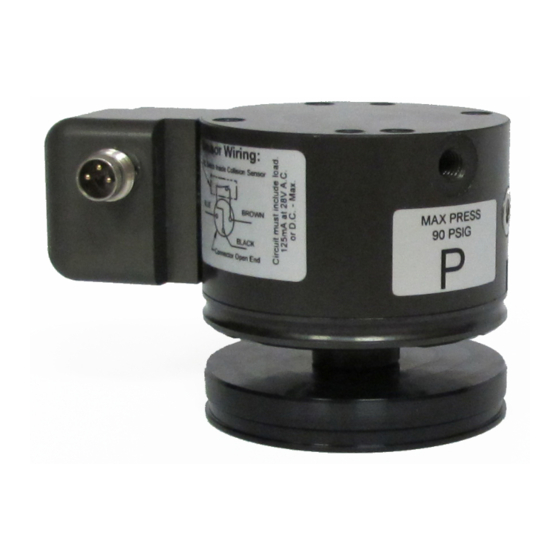
Manual, Collision Sensor, SR‑48 Document #9610‑60‑1012‑06 3.2 Electrical Connection The Collision Sensor is connected to the user’s control wiring as a normally‑closed, dry‑contact switch. The following sketch details the connections between the internal switch and the pins in the connector block Table 6.2), utilize the brown‑black‑blue color assembly. -
Page 10: Pneumatic Connection
Manual, Collision Sensor,SR‑48 Document #9610‑60‑1012‑06 3.3 Pneumatic Connection Compressed air is to be supplied to the port marked “P” in the range of 20 psi to 90 psi. This port accepts #10‑32 or M5 pneumatic fittings. The pressure setting required for a particular application can be estimated using the procedure outlined in Section 3.3.1—Calculating Estimated Pressure Setting The exact pressure... - Page 11 Manual, Collision Sensor, SR‑48 Document #9610‑60‑1012‑06 Figure 3.2—Collision Sensor Loading Diagram Formulas: Axial Load (F) = F2 Torque (T) = F3*D3 Moment (M) = *D1 ‑ Information needed to calculate found within 9230 drawing on ATI website. NOTICE: F1, F2, & F3 consist of the sum of their respective static, dynamic, and working force components;...
-
Page 12: Obtain Required Pressure Setting
Manual, Collision Sensor,SR‑48 Document #9610‑60‑1012‑06 3.3.1.2 Obtain Required Pressure Setting The pressure setting required can be approximated from the following formula: P = Pm + Pt + Pf + Pm + Pt Where Pm, Pt, and Pf are the pressure components related to the moment, torque, and force load components expected at the break‑away. -
Page 13: Determining Exact Pressure Required
Manual, Collision Sensor, SR‑48 Document #9610‑60‑1012‑06 3.3.2 Determining Exact Pressure Required 1. Set the pressure approximately 5 psi (0.3 Bar) higher than the pressure calculated in Section 3.3.1—Calculating Estimated Pressure Setting. 2. Run the robot through a fully loaded cycle. 3. -
Page 14: Periodic Lubrication Instructions
Manual, Collision Sensor,SR‑48 Document #9610‑60‑1012‑06 5.1 Periodic Lubrication Instructions 5.1.1 Cover Plate and Stem Disassembly Note: Cleaning may be accomplished with a clean, dry rag. For more thorough cleaning, use isopropyl alcohol. 1. Remove the (4) socket head cap screws securing the cover plate assembly to the body using a 2.5 mm hex key (refer to Figure 5.11). -
Page 15: Cover Plate And Stem Cleaning And Lubrication
Manual, Collision Sensor, SR‑48 Document #9610‑60‑1012‑06 5.1.2 Cover Plate and Stem Cleaning and Lubrication 1. Clean the lubricant from the working surfaces of the cam and the clearance ring. Set the cover plate assembly aside for later re‑use (refer to Figure 5.22). -
Page 16: Cover Plate And Stem Re-Assembly
Manual, Collision Sensor,SR‑48 Document #9610‑60‑1012‑06 5.1.3 Cover Plate and Stem Re‑assembly 1. Apply a generous coating of CRC Extreme Pressure Moly C.V. Joint Grease (Moly Grease) to the top surface of the piston (refer to Figure 5.4). 2. Apply a generous coat of moly grease to each of the (3) ball segments on the stem assembly and to the rounded edge of the shoulders between the ball segments. -
Page 17: Troubleshooting
Manual, Collision Sensor, SR‑48 Document #9610‑60‑1012‑06 6. Troubleshooting The Collision Sensor will offer exceptional performance in normal operation. However, the Collision Sensor is not a compliance device and frequent collisions should be avoided to maximize performance and life. The Collision Sensor is designed to automatically return to its working position once the disturbing force is removed. -
Page 18: Cable Replacement
Manual, Collision Sensor,SR‑48 Document #9610‑60‑1012‑06 6.1 Cable Replacement If the cable attached to your Collision Sensor becomes broken or worn, replacement cables may be purchased as follows: Collision Sensor model number: 9610‑061‑Pxx‑XX‑x‑x‑x (x = any value). Table 6.2—Cable Choices Cable Number Description No cable purchased with Collision Sensor –... -
Page 19: Spring Conversion
Manual, Collision Sensor, SR‑48 Document #9610‑60‑1012‑06 6.2 Spring Conversion The collision sensor may be equipped with an assist spring which provides a force equivalent to 5 psi (P05), 10 psi (P10) or 15 psi (P15) of applied pressure. An SR‑48 may be field converted to add an assist spring or to contain a different range spring. -
Page 20: Seal Replacement
Manual, Collision Sensor,SR‑48 Document #9610‑60‑1012‑06 6.3 Seal Replacement 1. Disassemble cover assembly and stem assembly per Section 5.1.1—Cover Plate and Stem Disassembly. 2. Remove the M4 dog point set screw using a 2.5 mm hex key (refer to Figure 5.45) (If unit is equipped with an assist spring, temporarily place the stem assembly on top of the piston and push down while removing the set screw.) 3. -
Page 21: Weld Splatter Shield Replacement
Manual, Collision Sensor, SR‑48 Document #9610‑60‑1012‑06 6.4 Weld Splatter Shield Replacement 1. Remove (2) M2.5 x 6 flat head socket cap screw and shield retainer (refer to Figure 6.34). 2. Remove weld shield seal and discard. 3. Install new EPDM seal by stretching the center hole over the stem. 4. -
Page 22: Drawings
Manual, Collision Sensor,SR‑48 Document #9610‑60‑1012‑06 8. Drawings 8.1 SR‑48 Collision Sensor Assembly Drawing Pinnacle Park • 1031 Goodworth Drive • Apex, NC 27539 USA • Tel: 919.772.0115 • Fax: 919.772.8259 • www.ati‑ia.com... -
Page 23: Collision Sensor Assembly Replacement Parts
Manual, Collision Sensor, SR‑48 Document #9610‑60‑1012‑06 8.2 SR‑48 Collision Sensor Assembly Replacement Parts Pinnacle Park • 1031 Goodworth Drive • Apex, NC 27539 USA • Tel: 919.772.0115 • Fax: 919.772.8259 • www.ati‑ia.com... - Page 24 Manual, Collision Sensor,SR‑48 Document #9610‑60‑1012‑06 Pinnacle Park • 1031 Goodworth Drive • Apex, NC 27539 USA • Tel: 919.772.0115 • Fax: 919.772.8259 • www.ati‑ia.com...
-
Page 25: Terms And Conditions Of Sale
Manual, Collision Sensor, SR‑48 Document #9610‑60‑1012‑06 9. Terms and Conditions of Sale The following Terms and Conditions are a supplement to and include a portion of ATI’s Standard Terms and Conditions, which are on file at ATI and available upon request. ATI warrants to Purchaser that Collision Sensor products purchased hereunder will be free from defects in material and workmanship under normal use for a period of one (1) year from the date of shipment.
Need help?
Do you have a question about the SR 48 and is the answer not in the manual?
Questions and answers