Advertisement
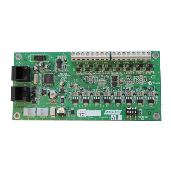
8 Zone Conventional Board
Installation guide
introduction
The 8 Zone Conventional Board Fast Fit Kit consists of:
•
1 x 8 Zone Conventional Board
•
1 x 220mm RJ45M Comms / power Cable
•
1 x 250mm 2 way IDT Power Cable
•
4 x 3 x 6mm self tap screws (only required for the
ABS cabinet)
•
4 x M3 x 6mm screws (only required for the metal
cabinet)
•
4 x standoffs (only required for the metal cabinet)
•
8 x 3K3Ω EOL resistors
•
8 x 10uF 50V Bi-Polar EOL Capacitors
Description
The 8 Zone Conventional Board provides 8 monitored
conventional zones. Each zone can accommodate up to
40 conventional detectors (32 in UK) and can be
programmed to function in one of the following modes:
•
Normal (Latching)
•
Non-Latching
•
Self Reset
•
Dependency A, B and C
•
Investigation
The board has a programmable End Of Line (EOL)
feature that allows either a 3K3Ω, 4K7Ω, 6K8Ω or
10KΩ resistor value to be used on all zones.
Alternatively, the EOL can be a 10uF capacitor which is
required to support the head removal feature when
Apollo diode bases are used on the conventional zone.
Note: If using 10uF EOL with NZ 1997 MCP's the
Alarm activation time will be outside the NZS 4512
standards
Installation
Observe anti-static precautions at all times
BRD82ZICC3
B UZZER
S ILENCE
LK1
SW27
CONFIG
COMMS
CN6
CN8
KEYSWITCH
SWxxxx
Figure 1: Example of Internal Cabling of the Loopsense (ABS cabinet)
PRINTER
PARALLEL
SERIAL
LCD BL
CN3
CN2
CN4
RESET
SW28
PWR LINK
PWR LINK
CN9
CN10
Power down and disconnect the batteries
ABS Cabinet (new battery cabinet may be required if
a lower backpan mounting position is used)
1. Mount the board on suitably spaced moulded
backpan bosses using the 4 x 6mm self tap screws.
Metal Cabinet (standoffs fitted to lower left hand side
of the backpan)
2. If necessary fit the stand offs to the suitably spaced
captive nuts in the lower right hand side backpan
position
3. Mount the board onto the standoffs using the 4 M3
x 6mm screws
Connecting to the FACP
1.
Using the supplied Comms cable connect CN2 on
the 8 Zone Board to the RS485 Comms out of the
CIE main board or previous internal backpan board.
2.
Connect power cable from CN8 of Main Brd to
CN4 of the Zone Brd. See Figure 1
3.
Bring the field cabling into the FACP through a
suitable knockout and terminate to the required
Zones (TB1, TB2).
4.
Set Address SW (Addresses 1 to 15 can be used).
See Figure 2
5.
Power up the panel and reconnect the batteries
6.
Program the 8 Zone Board using LoopMaster or
ConfigManager Tool.
7.
Test
BRD82MBA5
COMMS
AUX OUT1
INPUTS
LOOP 1
LOOP 2
+VE
C OM
1+
2+
3+
4+
A+
A-
B+
B-
A+
A-
B+
B-
RS485+
RS485-
SHD
SGD
CN1
CN2
CONTROLS
SW1
COMMS
RESET
CN10
K3
RS485
TERM
LOAD
CN6
DIAGNOSTICS
USB
DONGLE
CAB2200
CN2
8 ZONE CONVENTIONAL BOARD
A BATT BOX IS REQ
CN3
IF THIS BRD IS FITTED IN A
ABS ENCLOSURE
CN4 CN5
CAB2200
CAB2121 (+27v POWER)
MAN2982-2
Item Number: 4310-0082
N
A
SUPERVISED O/PS
RELAY 1
RELAY 2
RELAY 3
AUX OUT2
1+
1-
2+
2-
3+
3-
4+
4-
N/ O
C
N/C
N/ O
C
N/C
N/ O
C
N/C
+VE
0V
TB4
TB5
TB6
1
2
3
1
+VE
2
OUT1
3
OUT2
K1
EARTH MON.
PSU CONTROL
CN5
PSU1887
PWR OUT
CN8
PWR IN
CN9
CN7
+27V
0V
E TH
+27V
0V
CN1
OPTIONAL FITMENT POINT
CN2
CN3 CN4
1
Advertisement
Table of Contents

Related Manuals for Ampac 4310-0082


Summary of Contents for Ampac 4310-0082
- Page 1 MAN2982-2 8 Zone Conventional Board Item Number: 4310-0082 Installation guide Power down and disconnect the batteries introduction ABS Cabinet (new battery cabinet may be required if The 8 Zone Conventional Board Fast Fit Kit consists of: a lower backpan mounting position is used) •...
- Page 2 MAN2982-2 8 Zone Conventional Board Item Number: 4310-0082 Installation guide Connection and Settings RS485 Comms In from the previous RS485 Comms output or CN10 (Comms out) of the Main Control Card RS485 Comms Out to RS485 Comms In of the next RS485 Add-On board.
Need help?
Do you have a question about the 4310-0082 and is the answer not in the manual?
Questions and answers