Ampac FireFinder II Series Installation & Operation Manual
Control panel
Hide thumbs
Also See for FireFinder II Series:

Related Manuals for Ampac FireFinder II Series


Summary of Contents for Ampac FireFinder II Series
- Page 1 FIREFINDER SERIES II FIRE BRIGADE RESPONSE GUIDE FireFinder Fire Alarm Control Panel Series II SE Asia (CP10, MS1404) Installation, Commissioning & Operation MAN 2536-6...
- Page 2 FIREFINDER SERIES II FIRE BRIGADE RESPONSE GUIDE INCOMING ALARM CONDITION FIRE 1) INDICATION FIRE LED STEADY DESCRIPTION TYPE LOOP No SENSOR No STATUS ALARM LCD DISPLAY OF DESCRIPTION DATE TIME TYPE, ADDRESS, DATE TIME AND NUMBER OF ALARMS SENSOR ALARMS 1 OF XX 2) SOUNDER SILENCE OR SOUND EVACUATION PRESS KEY SOUNDER...
-
Page 3: Table Of Contents
TABLE OF CONTENTS Page No. About This Manual ........................1 Introduction ........................ 1 General Requirements ....................1 References......................... 1 Symbols ........................1 System Overview ........................2 FACP Configuration Examples ................... 3 FireFinder Description ......................5 Placing The Basic System Into Operation ................8 Unpacking ........................ - Page 4 5.14.6 SmartTerminal Controls and Indicators ............40 5.14.7 SMARTTERMINAL Screen Format ............40 5.14.8 Setting the SmartTerminal Controller Configuration in ConfigManager ..42 5.14.9 Setting the SmartTerminal Reporting Parameters in ConfigManager ..42 5.14.10 Trouble Shooting Chart ................43 5.14.11 Specifications .................... 44 5.15 Printer ........................
- Page 5 Address Setting ........................74 Glossary of Terms......................... 75 Definitions ..........................76 Maintenance .......................... 77 19.1 Regular Testing and Inspection ................77 19.1.1 General ..................... 77 19.1.2 Daily Check ....................77 19.1.3 Weekly Test ....................77 19.1.4 Monthly Test ....................78 19.1.5 Annual Test ....................
-
Page 6: About This Manual
FIREFINDER SERIES II INSTALLATION, COMMISSIONING & OPERATION About This Manual Introduction This manual contains all the information required to install, commission and operate the FireFinder SERIES II Fire Alarm Control Panel (FACP) fitted with Version 6 software and is only available to and for the use of personnel engaged in its installation, commissioning and operation. -
Page 7: System Overview
The FireFinder Series II is an Intelligent Analogue / Addressable and / or Conventional Fire Alarm Control Panel capable of supporting: AMPAC Discovery and XP95 Intelligent Detectors, Multisensor, Photoelectric, Ionisation, Thermal (heat) and CO detectors and Hochiki range of Detectors. -
Page 8: Facp Configuration Examples
FIREFINDER SERIES II INSTALLATION, COMMISSIONING & OPERATION FACP Configuration Examples S HD C N 2 R S 4 85 E O L CONTROLLER FACP L K 3 FA C P 0V A D D R ESS L S B M S B T B 3 Z D N 2 1 2 3 4... - Page 9 FIREFINDER SERIES II INSTALLATION, COMMISSIONING & OPERATION C N 5 C P U Figure 3: Typical Example of a CP10-4 Layout Page 4...
-
Page 10: Firefinder Description
FIREFINDER SERIES II INSTALLATION, COMMISSIONING & OPERATION FireFinder Description The following description does not relate to specific cabinets as the size of each cabinet will vary with the amount of hardware fitted. The heart of the FireFinder Series II consists of two boards collectively known as the Controller. These boards are the Main Board and the CPU board. - Page 11 COMMISSIONING & OPERATION The FireFinder Series II has an internal ASPI (Ampac Serial Peripheral Interface) serial bus. This serial bus provides interfacing to the Brigade /PSU Monitor Board and if required up to eight (8) Sounder Board/s. FireFinder Series II has a second serial interface that connects to ancillary boards these can be used to control and monitor field plant equipment.
- Page 12 FIREFINDER SERIES II INSTALLATION, COMMISSIONING & OPERATION CN10 CN18 CN20 Figure 6: Basic FACP Configuration Page 7...
-
Page 13: Placing The Basic System Into Operation
FIREFINDER SERIES II INSTALLATION, COMMISSIONING & OPERATION Placing The Basic System Into Operation Unpacking Carefully unpack the FireFinder. The package should include: FireFinder SERIES II Fire Alarm Control Panel An Operators manual Anti-Static Precautions To prevent damage to components, modules and boards, anti-static precautions MUST be observed while performing any task within the FACP. -
Page 14: Operational Parameters
& OPERATION Operational Parameters GENERAL Communication Protocol AMPAC XP95 / Discovery Max No of Devices per Loop Max No of Devices per FACP Max No of Devices per Conventional Zone 2 core. 1.5 to 2.5mm² Max loop resistance 50Ω. Cable Loop Characteristics Max core to core capacitance 0.5uF... -
Page 15: Cabling Recommendations
FIREFINDER SERIES II INSTALLATION, COMMISSIONING & OPERATION Cabling Recommendations Conventional Zones Cabled in red Twin Plastic Sheath (TPS), Fire rated Radox or approved equivalent. Analogue Loop Two core cable. The minimum cable size is 0.75mm , the maximum loop resistance is 50 ohms and the maximum loop distance is 2km. -
Page 16: Power Supplies And Ac Mains Installation
FIREFINDER SERIES II INSTALLATION, COMMISSIONING & OPERATION Power Supplies and AC Mains Installation Generally the AC Mains will be connected to either a 2 Amp, 5 Amp or 18Amp 27 volt supply. These supplies will be either mounted in the upper or lower right hand corner of the cabinet with the Brigade Board mounted above or below. -
Page 17: Connecting The Mains Power To The Power Supply
FIREFINDER SERIES II INSTALLATION, COMMISSIONING & OPERATION 4.8.2 Connecting the Mains Power to the Power Supply 5 AMP Power Supply Output Voltage: is set to 27.4 Volts. Mains cable should be no less than 0.75mm POWER CABLE BLUE (NEUTRAL) EARTH BROWN (ACTIVE) (GREEN) FUSE BLOCK... -
Page 18: Brigade / Psu Monitor Board
FIREFINDER SERIES II INSTALLATION, COMMISSIONING & OPERATION Brigade / PSU Monitor Board The Brigade / PSU Monitor Board monitors and controls the power supply, battery charging, monitored / un-monitored inputs, outputs and the 7 relay outputs. Providing the Power supply has adequate capacity, monitored Bell/Sounder O/P’s are capable of driving 2 X 2Amp circuits. - Page 19 FIREFINDER SERIES II INSTALLATION, COMMISSIONING & OPERATION Sounder 1.1 Sounder 1.1 To CN7 of the Main Controller Board Sndr 1.2 Monitored Sounder 1.2 Required Ohms Un-monitored F.A.R.E. Monitored Required F.A.R.E. Mon. Sounder 2 Un-monitored Sounder 2 Sounder 2 Aux Power Power O/P 1 &...
-
Page 20: Battery Connections (Tb1)
FIREFINDER SERIES II INSTALLATION, COMMISSIONING & OPERATION 4.9.1 Battery Connections (TB1) A FireFinder requires two (2) 12 volt batteries. The batteries should be placed into the bottom right hand side of the cabinet. A red and black lead coming from TB1 on the Brigade Board will be clearly seen in the same area, this lead is to be connected to the batteries red to positive and black to negative once the system is operating on Mains supply. -
Page 21: Relay Output Connections (Tb6 - Tb10)
FIREFINDER SERIES II INSTALLATION, COMMISSIONING & OPERATION 4.9.4 Relay Output Connections (TB6 – TB10) The relay contacts are connected as shown below. Brigade/PSU Note 1: BATT FAIL DISABLE F.W.R.E. VALVE MON ALARM Monitor Board = 1A Fused monitored NO C NC NO C NC NO C NC NO C NC... -
Page 22: Main Board
FIREFINDER SERIES II INSTALLATION, COMMISSIONING & OPERATION 4.10 Main Board The Main Board is the "heart" of the FACP and carries the devices for interconnecting to all the other Boards, a buzzer for auditory indication, the backlight power supply for the LCD and CPU Reset. The Main CPU is mounted on this board and connected to it by CN11. -
Page 23: Front Panel Board
FIREFINDER SERIES II INSTALLATION, COMMISSIONING & OPERATION 4.11 Front Panel Board The Front Panel Board provides the buttons used to control the FACP as well as all LED indications. All LED’s are surface mounted and the buttons are embedded within the board. The LCD is viewed / protected by a clear Perspex screen. -
Page 24: Main Cpu
FIREFINDER SERIES II INSTALLATION, COMMISSIONING & OPERATION 4.12 Main CPU The Main CPU holds the main central processing unit for the FACP. The CPU is a 4-layer surface mount board The processor (IC1) is a Motorola MC68302, running at 16MHz. ... -
Page 25: Slave Cpu
FIREFINDER SERIES II INSTALLATION, COMMISSIONING & OPERATION 4.13 Slave CPU The Slave CPU (Central Processing Unit) provides the interfacing signals and I/O’s required to allow the FACP to connect / communicate to a variety of termination boards. Automatic Termination Board Sensing A unique feature of the Slave CPU is its ability to automatically sense the type of board it is connected to without the user having to configure the board to suit. -
Page 26: Conventional Zone Board
FIREFINDER SERIES II INSTALLATION, COMMISSIONING & OPERATION 4.14 Conventional Zone Board Under the control of a Slave CPU the Conventional Zone Board provides the interface between it and the external conventional devices. 16 Conventional zones, with a limit of 32 conventional detectors can be connected to TB4 to TB1. -
Page 27: Addressable Loop Termination Board
Connect the XP-95 / DISCOVERY loop to the panel as shown below. AMPAC strongly recommend that the LoopManager test set is used to check that the AMPAC loop has been correctly installed and commissioned before connecting it to the FireFinder™. -
Page 28: Expanding The Facp With Compatible Firefinder Boards
FIREFINDER SERIES II INSTALLATION, COMMISSIONING & OPERATION Expanding the FACP with Compatible FireFinder Boards Ancillary Services The FACP has been designed such that detectors and/or call points, in addition to giving an alarm and calling the fire brigade, will close or open circuits of ancillary services by means of relays or similar devices. -
Page 29: Expansion Board
FIREFINDER SERIES II INSTALLATION, COMMISSIONING & OPERATION Expansion Board The Expansion Connection Board is used to increase the capacity of the controller from 4 Slave CPU’s to 8. Connection from the Controller to the Expansion Board, which must be mounted within 200mm of the Controller, is made via a 20 way flat cable Slave CPU number 5 is an integral part of the Expansion Board, only Slave CPU’s 6, 7 and 8 are plug ins. -
Page 30: 16/16 Input / Output Board
FIREFINDER SERIES II INSTALLATION, COMMISSIONING & OPERATION 16/16 Input / Output Board The Input / Output Board is connected to the slave CPU via CN1 and acts as the interface between the Slave CPU, 8 Way Relay Board and the 16 Way Opto Input Board. Dependant on the panel configuration a maximum of 8 Input / Output boards can be daisy chained together. -
Page 31: Way Input Board
FIREFINDER SERIES II INSTALLATION, COMMISSIONING & OPERATION 16 Way Input Board Opto-Inputs: Up to 16 inputs can be connected to the 16 Way Input Board. These inputs are required to be voltage free contacts as shown below. AS AN EXAMPLE INPUTS 1 AND 16 CONNECTED TO VOLTAGE-FREE CONTACTS 3 4 5 6 7... -
Page 32: External Control Interface Board
FIREFINDER SERIES II INSTALLATION, COMMISSIONING & OPERATION External Control Interface Board The External Control Interface Board provides interfacing for 8 external 0V control inputs that are configured as outlined in the table below. The FACP is programmed to recognise the individual inputs as listed and initiates the appropriate response. -
Page 33: Zone & General Indicator Card
FIREFINDER SERIES II INSTALLATION, COMMISSIONING & OPERATION Zone & General Indicator Card The General Indicator Card comes in two versions each consisting of a front clip on surround, decal, mounting frame, PCB and is clipped into the front panel of the FACP to provide visual LED indication of;... -
Page 34: Way Sounder / Bell Monitor Board
FIREFINDER SERIES II INSTALLATION, COMMISSIONING & OPERATION 5.10 8 Way Sounder / Bell Monitor Board The 8 way Sounder Monitor Board allow a larger number of bells and sounders to be connected to the FireFinder™ System. The 8 way Sounder Monitor Board is built in two versions: 1. -
Page 35: Led Mimic Board
FIREFINDER SERIES II INSTALLATION, COMMISSIONING & OPERATION 5.11 LED Mimic Board The LED Mimic Board has been designed to communicate with the Main Panel using RS485 protocol so as it can remotely mimic that panel’s LED’s and switches. The Mimic therefore can display the status of 32 Zones, 5 specific common outputs ( Alarm, Pre-alarm, DBA, Fault, Normal ) and can be configured to have 5 input switches ( Mimic Reset, Lamp Test, Buzzer Mute, Bell Disable, Evacuate ), 1 remote Buzzer output as well as 1 software configurable 1A relay output and... - Page 36 FIREFINDER SERIES II INSTALLATION, COMMISSIONING & OPERATION LED DISPLAY POWER ON NORMAL FAULT O F F ALARM C N 5 S W 2 PRE-ALARM PREALM ADDRESS FAULT SYSTEM NORMAL NORM LEDS FLASH RESET SW MIMRST LAMP TEST SW LMPTEST BUZZER MUTE SW BUZZMTE BELL ISOLATE SW BELLISO...
- Page 37 FIREFINDER SERIES II INSTALLATION, COMMISSIONING & OPERATION LED DISPLAY POWER ON NORMAL FAULT RESET SW ALARM LAMP TEST SW ADDRESS BUZZER MUTE SW SYSTEM DFCT LEDS FLASH BELL ISOLATE SW N OR M EVACUATION SW CPU RESET REMOTE BUZZER PRE-ALM LAMP 26 WAY RIBBON TEST...
-
Page 38: High Level Interface Expander
FIREFINDER SERIES II INSTALLATION, COMMISSIONING & OPERATION 5.12 High Level Interface Expander Hardware The High Level Interface Expander consists of a serial port under the control of a microcontroller. Communications between the FACP and this board is via the RS485 control bus with each board having a dedicated link and selectable 4 bit address. -
Page 39: Communications Extender Board
FIREFINDER SERIES II INSTALLATION, COMMISSIONING & OPERATION 5.13 Communications Extender Board The Communications Extender Board is mounted inside the FACP and provides protected RS485 communications and 27VDC to the SmartTerminal Termination Board/s and LCD/s and LED Mimics. CH16 +24VDC C O M CN20 TO NEXT SmartTerminal RJ45... -
Page 40: Smartterminal
FIREFINDER SERIES II INSTALLATION, COMMISSIONING & OPERATION 5.14 SmartTerminal SmartTerminal connects to the FireFinder Fire Alarm Control Panel (FACP) via the RS485 multidrop communication port. Generally it is designed to be used anywhere where the status of the FACP is required to be monitored by local personnel and limited control is required. ... -
Page 41: Mechanical
FIREFINDER SERIES II INSTALLATION, COMMISSIONING & OPERATION 5.14.2 Mechanical SmartTerminal can be supplied in three variants Slim Line ABS (externally powered) BX1 ABS (externally powered) and BX1 ABS (internally powered) and consists of; Note: A Communications Extender Board will be required if the Comms Bus in the FACP is fully utilised and / or if one is not fitted. -
Page 42: Installation & Cabling
FIREFINDER SERIES II INSTALLATION, COMMISSIONING & OPERATION 5.14.3 Installation & Cabling The Communications Extender Board should be mounted into the FACP and cabled as shown below. It should be noted the Communications Extender Board and its supporting plate is mounted in a piggy back fashion onto one of the loop / zone boards. -
Page 43: Setting The Address
FIREFINDER SERIES II INSTALLATION, COMMISSIONING & OPERATION 5.14.4 Setting the Address Open the front door; locate the “CONFIG” button situated on the left hand side of the PCB and press for 3 seconds. The buzzer and “Config” LED will double beep and flash respectively to indicate that the Configuration mode has been entered. -
Page 44: Operation
FIREFINDER SERIES II INSTALLATION, COMMISSIONING & OPERATION 5.14.5 Operation The operation of SmartTerminal can be considered to be in one of three states, these are; 1. Power up - when the SmartTerminal is initialising 2. Normal - when the SmartTerminal address has been set and is communicating with the FACP, reporting normal / abnormal conditions and controlling the FACP via the front panel controls 3. -
Page 45: Smartterminal Controls And Indicators
FIREFINDER SERIES II INSTALLATION, COMMISSIONING & OPERATION 5.14.6 SmartTerminal Controls and Indicators All controls, except for the Enable / Disable keyswitch, are of a momentary push button style. Figure 45: SmartTerminal Front Panel Layout 5.14.7 SMARTTERMINAL Screen Format There are 3 events that can be reported and displayed by SmartTerminal. The types of event are; 1. - Page 46 FIREFINDER SERIES II INSTALLATION, COMMISSIONING & OPERATION In the event of a loss of communications, for a period of greater than 15 seconds the LCDA will default to the No Communications screen. The format for this screen No Communication Device Isolate / Disables: If configured the screen format for reporting loop / sensor / zone disable condition is: <point location>...
-
Page 47: Setting The Smartterminal Controller Configuration In Configmanager
FIREFINDER SERIES II INSTALLATION, COMMISSIONING & OPERATION 5.14.8 Setting the SmartTerminal Controller Configuration in ConfigManager Right click on the Controller icon and select “Edit Module Types” to bring up the following screen/s. Figure 46: The Controller Edit / Add Module Types Screens Click within the check box to “tick”... -
Page 48: Trouble Shooting Chart
FIREFINDER SERIES II INSTALLATION, COMMISSIONING & OPERATION In the above example Card 1 & 2; Are active Are situated in the factory floor area 8 Will display all Alarms Will not display any Faults, and Will not display any Disables Card 3 ... -
Page 49: Specifications
FIREFINDER SERIES II INSTALLATION, COMMISSIONING & OPERATION 5.14.11 Specifications MECHANICAL Dimensions ABS Cabinet: ( mm ) 195mm (H) x 345mm (W) x 50mm (D) ENVIROMENTAL Temperature: -5ºC to + 55ºC Humidity: 25% to 75% INPUT POWER Operating Voltage ( nominal ): 27VDC Operating Voltage ( minimum ): 18VDC... -
Page 50: Printer
FIREFINDER SERIES II INSTALLATION, COMMISSIONING & OPERATION 5.15 Printer Specifications Printing method: directed impact dot matrix Interface: 8 bit parallel interface Printing mechanism: 4/6 pin shuttle Interface port: 26 PIN flat plug 5.15.1 Indicators and Buttons The front panel has an LED indicator and two buttons SEL (SELECT), LF (LINE FEED). -
Page 51: Maintenance
FIREFINDER SERIES II INSTALLATION, COMMISSIONING & OPERATION Self-Test Mode With power applied (green LED illuminated) push the SEL button. This will turn off the LED. Press and hold in the LF button, then press the SEL button again and the printer will enter the Self Test mode. - Page 52 FIREFINDER SERIES II INSTALLATION, COMMISSIONING & OPERATION Mechanism Release Hinges Button PUSH Push Buttons Paper Note: Ink Ribbon Front Door Removed Cassette Note: Replacement Paper Roll Front Door Removed Figure 50: Head Mechanism Rotation and Paper Roll Removal / Insertion Take out the empty paper roll and roller Put the new paper roll onto the paper roller and replace as shown above.
-
Page 53: Printer Connections And Jumpering
FIREFINDER SERIES II INSTALLATION, COMMISSIONING & OPERATION 5.15.3 Printer Connections and Jumpering Mounted on the back of the printer mechanism is the PCB that carries the; Connectors for interconnection to the Main Board, Jumper links required to set the programmed print modes; and ... -
Page 54: Expanding The System Through Networking
FIREFINDER SERIES II INSTALLATION, COMMISSIONING & OPERATION Expanding the System Through Networking Expanding the system can be achieved in various ways and requires the use of boards specifically designed for communications purposes and boards that actually expand the system. Communications: Network Interface Card The Network Interface Board provides the RS485 communication buses via CN18 on the Main Controller (Loop Comms) to allow the networking of multiple panels in different combinations, e.g. - Page 55 FIREFINDER SERIES II INSTALLATION, COMMISSIONING & OPERATION PANEL 1 CN17 MAIN CONTROL BOARD (BRD85MBA) CH16 CH15 CN20 CN13 CN14 CN15 CN11 CN18 RN20 RN17 CN10 PSU MONITOR CN16 BRIGADE I/F 16 Way MODEM 16 Way EXPANSION PANEL EXPANSION LEDS FRONT PANEL PRINTER CN17 MAIN CONTROL BOARD (BRD85MBA)
- Page 56 FIREFINDER SERIES II INSTALLATION, COMMISSIONING & OPERATION RS 232 RS 485 CN17 MAIN CONTROL BOARD (BRD85MBA) CH16 CH15 CN20 RJ45 CN13 CN14 CN15 CN11 CN18 RS485 HLI CONTROLLER (BRD43SPB) FACP MODBUS RN17 RN20 FACP 0V ADDRESS ZDN2 1 2 3 4 RS 232 RJ45 RS 485...
-
Page 57: Conventional Network Board
FIREFINDER SERIES II INSTALLATION, COMMISSIONING & OPERATION Conventional Network Board The Conventional Network Board provides a simple wired OR interface between FireFinder systems and existing Singapore Fire Systems such as the Patent 88, allowing reuse of existing cabling ALARM OUT LED SILENCE OUT LED RESET OUT LED ZONE OUT LED... -
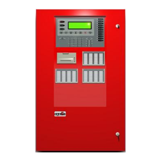
Page 58: Firefinder Control Panel
FIREFINDER SERIES II INSTALLATION, COMMISSIONING & OPERATION FireFinder Control Panel POWER ON PRE-ALARM FIRE TEST MODE FAULT SOUNDER STATUS LCD WINDOW SUPPLY FAULT DISABLED EARTH FAULT SYSTEM FAULT SOUNDER PREVIOUS BUZZER INDICATOR NEXT EVACUATE RESET SILENCE SILENCE TEST F.W.R.E. ACTIVE F.A.R.E. - Page 59 FIREFINDER SERIES II INSTALLATION, COMMISSIONING & OPERATION PREVIOUS This button is used for scrolling backwards through fire alarms, faults, or disablement’s displayed on the LCD. NEXT This button is used for scrolling forwards through fire alarms, faults, or disablement’s displayed on the LCD. BUZZER SILENCE Pressing this button will silence the panel buzzer, which sounds whenever there is a fire...
- Page 60 Pressing the MENU button will display the main menu on the LCD. Similarly pressing the FUNCTION button will display the function menu on the LCD. APS/ APH 26/2/2007 08:05:45 AMPAC PH: +61 8 9201 6100 SYSTEM IS NORMAL AC: 1S ALM: 000...
-
Page 61: Functions And Menus
Functions And Menus The Default LCD Display In its normal state the FireFinder™ will display a screen similar to that shown below. APS/ APH 26/2/2007 08:05:45 AMPAC PH: +61 8 9201 6100 SYSTEM IS NORMAL AC: 1S ALM: 000 PALM: 000... -
Page 62: The Main Menu
FIREFINDER SERIES II INSTALLATION, COMMISSIONING & OPERATION The Main Menu The MAIN MENU is accessed by pressing MENU. MAIN MENU 0: ALARMS 1 :PREALARMS 2: FAULTS 3: DISABLES 4:STATUS 5 :TEST 6: SOUNDERS 7: PRINTER: SELECT NO. AC: 2S ALM: 000 PALM: 000 FLT: 000 DIS: 000... - Page 63 FIREFINDER SERIES II INSTALLATION, COMMISSIONING & OPERATION Network Note: This option is only available if the system configuration is networked. Is pressed to gain access to NETWORK STATUS. DISPLAY NETWORK STATUS 0: NETWORK POINTS 1: REMOTE SLAVE MODULES 2: REMOTE EXTERNAL LED MIMIC MODULES SELECT NO.
-
Page 64: Testing Menu
FIREFINDER SERIES II INSTALLATION, COMMISSIONING & OPERATION Is pressed to access SYSTEM STATUS - .For a network panel SYSTEM STATUS ALARMS: 0000 PRE-ALARMS: 0000 DISABLES: 0000 DEVICE FAULTS: 0000 MOD FAULTS: 00 WDG: 00 LOOP FAULTS: 00 VERSION: 6.1 EN54 AC: 2S ALM: 000 PALM: 000... -
Page 65: Lamp Test
FIREFINDER SERIES II INSTALLATION, COMMISSIONING & OPERATION 9.2.3 Lamp Test Is pressed to initiate a Lamp Test: The test will sequentially flash the LED’s on the front panel and illuminate the various segments on the LCD display. 9.2.4 Sounders ... -
Page 66: Main Functions
FIREFINDER SERIES II INSTALLATION, COMMISSIONING & OPERATION Main Functions LEVEL III MAIN FUNCTIONS 0: DATE 1: TIME 2: DAY/NIGHT 3: LOGS 4: TESTS 5: I/O 5: PASSWORD 6: PROG SELECT NO. AC: 3S ALM: 000 PALM: 000 FLT: 000 DIS: 000 Figure 68: The Level II &... -
Page 67: The Function Test Facility
FIREFINDER SERIES II INSTALLATION, COMMISSIONING & OPERATION The type of log, number and totals logged, date and time of the ALARM, FAULT, DISABLE, SYSTEM or I/O as well as device information will be displayed. The SYSTEM screen displays events and watchdog activity. From these screens the operator can select two other facilities, they are;... -
Page 68: Function Manual I/O Control
FIREFINDER SERIES II INSTALLATION, COMMISSIONING & OPERATION 10.6 Function Manual I/O Control Press To display the Manual I/O Control menu MANUAL I/O CONTROL 0: INPUT 1 :OUTPUT 2: REMOVE ALL MANUAL CONTROL SELECT NO. AC: 3S ALM: 000 PALM: 000 FLT: 000 DIS: 000 Figure 69: The Manual I/O Control Menu... -
Page 69: Function Access (Level Ii) / Passwords (Level Iii)
Enter 9999 into the password field; Take note of the 4 digit password button displayed on the screen; Contact the AMPAC head office and quote this number; A temporary password will be issued to allow access to the level 3 functions ... -
Page 70: Conventional Zone Programming
FIREFINDER SERIES II INSTALLATION, COMMISSIONING & OPERATION 10.8.1 Conventional Zone Programming Press Zone: Key in the zone number and enter or change the description ( DESC ) by pressing buttons to move the flashing underline or curser. The numeric buttons multiple times to access characters while at the same time using EDIT Zx DESC AND TYPE STRINGS DESC <... -
Page 71: Device Programming
FIREFINDER SERIES II INSTALLATION, COMMISSIONING & OPERATION After scrolling through the groups and entering what I/O GROUPS will be turned on by what module/s or device/s in a zone/s the operator is prompted to press ENTER to confirm the entries and / or changes. 10.8.2 Device Programming ... -
Page 72: Output Programming
FIREFINDER SERIES II INSTALLATION, COMMISSIONING & OPERATION 10.8.4 Output Programming Press OUTPUT: By following the screen prompts as above Add, Edit or Delete an output in a panel or on a loop. 10.8.5 Watchdog Press This Function provides a counter to record any re-initialisation of the processor. If due to a software failure the panel is automatically reset then the counter will increment by 1. -
Page 73: Mismatch Detected
FIREFINDER SERIES II INSTALLATION, COMMISSIONING & OPERATION 10.8.8 Mismatch Detected If a mismatch is detected the Normal Default Screen will change to that shown below. Go to the Programming Menu and select either Resolve Extra Modules and Devices then ... -
Page 74: Incoming Fire Alarm Signal
FIREFINDER SERIES II INSTALLATION, COMMISSIONING & OPERATION Incoming Fire Alarm Signal Will operate the red common LED fire indicator Will display location of fire alarm origin on the LCD Will activate external alarm. Will activate the internal FACP buzzer. ... -
Page 75: Accessing A Loop, Sensor Or Zone
FIREFINDER SERIES II INSTALLATION, COMMISSIONING & OPERATION Accessing a Loop, Sensor or Zone LOOP OR SENSOR From the default display, press LOOP Enter the loop number you wish to interrogate then press SENSOR. Press the button for the sensor number. ... -
Page 76: Rs232 Modem / Programming / Debug Interfacing
Rx Data DB9F CONNECTOR DB9F CONNECTOR ( Female Rear View ) ( Female Rear View ) Plugs into FACP To Modem or PC Figure 83: Modem / Programming / Debug Cabling Note: Debug/Notebook cables are available from AMPAC. Page 71... -
Page 77: Certification Information
FIREFINDER SERIES II INSTALLATION, COMMISSIONING & OPERATION Certification Information The FireFinder™ is designed and manufactured by: AMPAC TECHNOLOGIES PTY LTD 7 Ledgar Rd Balcatta WA 6021 Western Australia HEAD OFFICE 61-8-9242 3333 FAX: 61-8-9242 3334 Manufactured to: Certificate of Compliance Number:... -
Page 78: Troubleshooting Chart
Can not access Function menu Incorrect Password entered Ring AMPAC and directions will be given to Forgotten password provide you with a temporary code An Analogue Fault occurs when using a A 1.8k Ohm resistor must be placed in series with... -
Page 79: Address Setting
& OPERATION Address Setting BINARY ADDRESS SETTING (AMPAC) SERIES XP95 - ADDRESS DATA DIL SWITCH: ON = 1 OFF = 0 ADDRESS TAG FOR DETECTORS (I/O DEVICES) DIL switch setting DIL switch setting DIL switch setting DIL switch setting DIL switch setting... -
Page 80: Glossary Of Terms
FIREFINDER SERIES II INSTALLATION, COMMISSIONING & OPERATION Glossary of Terms ACF: ANCILLARY CONTROL FACILITY ACKD: ACKNOWLEDGED AHU: AIR HANDLING UNIT ALM: ALARM AVF: ALARM VERIFICATION FACILITY AZF: ALARM ZONE FACILITY AZC: ALARM ZONE CIRCUIT RELAY COMMON CONTACT (WIPER) CIC: CONTROLLER INTERFACE CARD CONNECTOR CPU: COMMON PROCESSOR UNIT... -
Page 81: Definitions
FIREFINDER SERIES II INSTALLATION, COMMISSIONING & OPERATION Definitions Addressable system - a fire alarm and detection system that contains addressable alarm zone facilities or addressable control devices. Alarm Verification Facility (AVF) - that part of the FACP, which provides an automatic resetting function for spurious alarm signals so that they will not inadvertently initiate Master Alarm Facility (MAF), or ACF functions. -
Page 82: Maintenance
FIREFINDER SERIES II INSTALLATION, COMMISSIONING & OPERATION Maintenance To ensure continuous reliability of the system, an agreement to carry out regular maintenance of the installation should be made with the manufacturer or manufacturer's representative or competent contractor. The arrangements for maintenance should be such as will ensure that a qualified person is available on call at all times to provide service in the event of any fault developing at the installation. -
Page 83: Monthly Test
FIREFINDER SERIES II INSTALLATION, COMMISSIONING & OPERATION 19.1.4 Monthly Test In addition to the Weekly Test specified above, the following Inspection and testing procedures should be carried out each month: Simulate fire conditions on alt alarm zones and reset the system to normal. Confirm with the monitoring station when the test has been completed. -
Page 84: Annual Test
FIREFINDER SERIES II INSTALLATION, COMMISSIONING & OPERATION 19.1.5 Annual Test The Annual Test should consist of all the inspection and testing procedures specified in Sub clause 2.14.4 and the following: The maintenance personnel should arrange to check the operation of at least 20 percent of the detectors in an Installation each year. -
Page 85: Quick Reference Guides
FIREFINDER SERIES II INSTALLATION, COMMISSIONING & OPERATION Quick Reference Guides The following guides; Prompt / assist an experienced operator to move through the Menu and Function facilities of the FACP without having to consult the main body this manual; and ... - Page 86 FUNCTION MENU OPTIONS FireFinder Quick Reference FUNCTION KEY ( TO ENTER FUNCTION FIELD ( ENTER PASSWORD ) ) MENU FUNCTION FUNCTION KEY ( TO ENTER FUNCTION FIELD ( ENTER PASSWORD ) ) DATE ( DD/MM/YYYY ) MENU MENU FUNCTION KEY ( TO ENTER FUNCTION FIELD ( ENTER PASSWORD ) ) FUNCTION FUNCTION SPACE...
- Page 87 NOTES: UNCONTROLLED DOCUMENT NOTE: Due to AMPAC’s commitment to continuous improvement specifications may change without notice.
Need help?
Do you have a question about the FireFinder II Series and is the answer not in the manual?
Questions and answers