Advertisement
Input Output Device Range
Installation guide
Description
The Input Output Device range comprises of the
following eight variants:
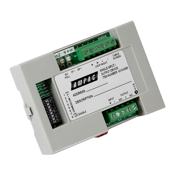
4210-0050 Single Input Output Device DIN Mount
4210-0051 Single Input Output Device Enclosed
4210-0052 Single Input Device DIN Mount
4210-0053 Single Input Device Enclosed
4210-0054 Three Input Output Device DIN Mount
4210-0055 Three Input Output Device Enclosed
4210-0056 Three Input Device DIN Mount
4210-0057 Three Input Device Enclosed
The DIN-Rail Mounted Devices are designed to be
mounted in an enclosure, clipped onto a standard
35mm DIN Rail (DIN46277) and secured using the built
in fixing. End stops can also be used to provide
additional security. Alternatively, the Devices can be
mounted direct to an enclosure back panel using the
internal preformed fixing holes.
The Enclosed variant Devices are each supplied within
a backbox and are suitable for surface mounting.
Note: the Devices are not intended for outdoor use
unless mounted in a suitable weatherproof enclosure.
The installation must conform to applicable local codes
and be carried out such that the Devices are not
subjected to exposure to temperatures exceeding the
maximum ambient, exposure to moisture, dust and
foreign bodies or exposure to a risk of mechanical
damage.
The Devices are all loop powered and are controlled by
the main fire control panel. The address is set using the
onboard DIL switch.
Each Device incorporates a bi-directional short circuit
isolator between the loop input and loop output
terminals which will protect the external Input
monitoring circuit against a single loop short circuit on
either side of the device.
Installation
DIN Rail
Clip the Input/Output Device to the standard 35mm
DIN rail using the Red locking clip located in the front of
the device. Alternatively, fix direct to the enclosure back
panel using appropriate M4 nuts and bolts.
Enclosed
Remove the clear ABS cover and securely mount the
backbox to a wall or suitable structure using the
integral fixing positions then install all external cables
Item Number: 4210-0050, 4210-0057
using the knock outs and/or cable tray entry points as
required.
1.
Connect the cables from the detection loop and the
conventional detector zone into the device. Ensure
that the earth continuity is maintained.
2.
Set the Device address using switches 1-7 on the
DIL switch in accordance with the address Table 2
and record the location description of the device
itself together with the address setting on the
device fascia label.
3.
For
Indications to On using switch 8 of the DIL switch.
This can be disabled upon completion of testing &
commissioning.
4.
Following commissioning ensure that the device is
securely fastened and replace the ABS clear cover.
Schematic Diagram (4210-0054)
LED Indications
The Device has several onboard LEDs which provide
indication for Input Active (Alarm), Output Active, Loop
Polling/Short Circuit Isolation and Fault conditions.
Function
Colour
Mode
Input
Yellow
On
Input
Yellow
Flashing
Output
Red
On
S/C Poll
Green
Flashing
S/C Poll
Green
On
MAN3052-2
purposes,
set
the
LED
Description
Input is active
Input is in fault
Output is active
Device
is
being
polled
Loop Short
1
Advertisement
Table of Contents

Related Manuals for Ampac 4210-0050


Summary of Contents for Ampac 4210-0050
- Page 1 Connect the cables from the detection loop and the following eight variants: conventional detector zone into the device. Ensure 4210-0050 Single Input Output Device DIN Mount that the earth continuity is maintained. 4210-0051 Single Input Output Device Enclosed Set the Device address using switches 1-7 on the...
- Page 2 MAN3052-2 Input Output Device Range Item Number: 4210-0050, 4210-0057 Installation guide Maximum Loop Current Consumption 4210-0050/1 (LEDs disabled) Quiescent Current 1.3mA Input On 1.5mA Output On 1.3mA Total (All On) 1.58mA Refer PDS for remaining range of devices. Commissioning It is important that the Device is tested thoroughly after installation by initiating an alarm condition at Input circuit.
- Page 3 MAN3052-2 Input Output Device Range Item Number: 4210-0050, 4210-0057 Installation guide Table 2 – Address DIL Switch Settings The address is set using the first seven switches of the 8 way DIL switch (marked address). Switch 8 enables and disables the on-board LED indications.
Need help?
Do you have a question about the 4210-0050 and is the answer not in the manual?
Questions and answers