Ampac SmartTerminal Installation, Commissioning & Operation
Hide thumbs
Also See for SmartTerminal:
- Installation, commissioning & operation (20 pages) ,
- Installation, comissioning & operation (20 pages)
Table of Contents
Advertisement
Quick Links
WORLD LEADER OF INNOVATIVE SOLUTIONS IN FIRE DETECTION AND ALARM SYSTEMS
SmartTerminal
Installation Commissioning & Operation
"Our aim is to provide
'Consistently Excellent Service'
in the eyes of our customers"
MAN1557-4
E
N
5
4
:
P
T
E
N
5
4
:
P
T
E
N
5
4
:
P
T
L
o
o
p
S
e
n
L
o
o
p
S
e
n
L
o
o
p
S
e
2
&
4
2
&
4
2
&
4
s
e
s
e
n
s
e
Advertisement
Table of Contents

Related Manuals for Ampac SmartTerminal


Summary of Contents for Ampac SmartTerminal
- Page 1 WORLD LEADER OF INNOVATIVE SOLUTIONS IN FIRE DETECTION AND ALARM SYSTEMS SmartTerminal & & & Installation Commissioning & Operation “Our aim is to provide ‘Consistently Excellent Service’ in the eyes of our customers” MAN1557-4...
-
Page 3: Table Of Contents
Installation & Cabling ....................8 SmartTerminal Termination Board Interconnection ............8 FACP Comms ........................ 8 Setting the Address...................... 9 Setting the SmartTerminal in LoopMaster ............... 10 Operation........................12 Controls and Indicators ..................... 13 LCD Screen Format ..................... 17 Specifications ......................19 Trouble Shooting Chart.................... -
Page 4: Introduction
Reports events from devices that are accessible to the host FACP. For example if the host FACP is configured with global access then the connected SmartTerminal reports events from all devices. If the host FACP is configured as local then the connected SmartTerminal reports events from devices that are directly connected to the host FACP. -
Page 5: Mechanical
SmartTerminal Europe Installation Commissioning & Operation Mechanical SmartTerminal is supplied in an ABS cabinet and consists of; The Main Card, with all controls and indicators mounted directly onto it 1 X Termination Board 2 X ABS door keys ... -
Page 6: Board Removal / Replacement
SmartTerminal Europe Installation Commissioning & Operation 2.1.3 Board Removal / Replacement If a PCB has to be removed the following precautions should be observed; Removing the door will provide better access to the boards and will ensure the hinges are not accidentally stressed. -
Page 7: Removing The Knockouts
SmartTerminal Europe Installation Commissioning & Operation 2.1.4 Removing the Knockouts The knock-outs should be removed with a sharp tap in the rim of the knock-out using a flat broad- bladed screwdriver. Note: Use of excessive force could damage the enclosure around the knock-out. -
Page 8: Installation & Cabling
SmartTerminal Europe Installation Commissioning & Operation Installation & Cabling The SmartTerminal is then connected to the FACP as shown below. SHIELDED COMMS CABLE +24VDC SHIELD COMMS AUX OUT1 INPUTS RELAY 1 RELAY 2 LOOP 1 LOOP 2 MONITORED O/PS RELAY 3... -
Page 9: Setting The Address
Use the “PREVIOUS (A-) and NEXT” (A+) keys to select the desired address. The default value for this address is 255 which is not a valid SmartTerminal address. The user must then select an address value from 1 to 30, i.e. the same address as that set in the FACP. The keys corresponding to C- (ACK) and C+ (RESET) are used in a similar manner to decrease and increase the LCD contrast level. -
Page 10: Setting The Smartterminal In Loopmaster
The Tree View Figure 6 The above shows the expanded view of the SmartTerminal add on type. In the case above the panel in question has 1 SmartTerminal assigned to it, entitled ‘Panel Add-on 1’. Selecting one of these add ons will update the Details Pane with the respective module’s information, while double-clicking on the add-on will open its editing dialog box. - Page 11 View and consists of a summary of all available SmartTerminal add ons assigned to the current panel. In the above, there are 2 add on SmartTerminal’s assigned to this panel, entitled ‘Panel Add- on 1’ and ‘Panel Add-on 5’ respectively.
-
Page 12: Operation
Installation Commissioning & Operation Operation The operation of SmartTerminal can be considered to be in one of three states, these are; 1. Power up - when the SmartTerminal is initialising 2. Normal - when the SmartTerminal address has been set and is communicating with the... -
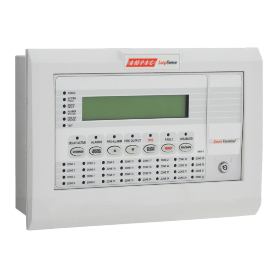
Page 13: Controls And Indicators
Europe Installation Commissioning & Operation Controls and Indicators All controls, except for the Enable / Disable keyswitch, are of a momentary push button style. Figure 10: SmartTerminal Front Panel Layout KEYSWITCH Access levels There are two levels of access. Access level 1 only the previous and next front panel controls are operative. All other controls operate in access level two. - Page 14 Press to display the previously displayed LCD screen Secondary Function Set SmartTerminal address – A – (minus) decrement number Active at access level 1 and 2 (Red) Illuminated when the FIRE output is active as a result of a fire condition.
- Page 15 SmartTerminal Europe Installation Commissioning & Operation (Red) The LED is illuminated when one or more devices are reporting a FIRE condition and are not disabled. Silence Buzzer Silences the panel buzzer. Buzzer is activated under the following conditions: Alarm condition ...
- Page 16 SmartTerminal Europe Installation Commissioning & Operation (Yellow) The LED is illuminated when one or more zone detectors, loop devices or panel outputs are disabled. Evacuate Turns on all alarm devices (visual and aural) outputs and activates the Fire indicator. The SILENCE / RESOUND or RESET control shall turn off all alarm devices (visual and aural).
-
Page 17: Lcd Screen Format
DEVICE► Note: The fault types only relate to devices. In the event of a loss of communications, for a period of greater than 15 seconds the SmartTerminal will default to the No Communications screen. The format for this screen is:... - Page 18 Address A- A+ C- C+ A - A +: adjusts the address 1 to 30, 30 being the maximum number of SmartTerminal’s that can be connected to the FACP, (default is 255 which is not a valid address). The function keys perform the following;...
-
Page 19: Specifications
2 core 1.5 to 2.5mm² COMMUNICATIONS Internal to FACP: RS485 External to FACP: RS485 Cabling Requirements: Twisted pair plus power Fault monitoring: O/C, S/C Maximum Number of SmartTerminal’s per FACP: Maximum Distance (from FACP): 1.2Kms. 4 line X 40 character - backlit Page 19... -
Page 20: Trouble Shooting Chart
Refer FACP LCD. This may identify where there is a break working in the communication line Check the SmartTerminal Diagnostic Config LED is flashing. If not the FACP is not communicating with the SmartTerminal. Check the RS485 cabling. If flashing check the SmartTerminal’s address. - Page 22 Fax: 64 9 443 8073 Fax: 61 8 9201 6101 Email: info.eu@ampac.net Email: info.nz@ampac.net Email: info@ampac.net Assessed to ISO9001 LPCB ref. no 952 (AMPAC Europe) (HEAD OFFICE) UNCONTROLLED DOCUMENT NOTE: Due to AMPAC’s commitment to continuous improvement specifications may change without notice.
Need help?
Do you have a question about the SmartTerminal and is the answer not in the manual?
Questions and answers