Advertisement
Quick Links
ADVANCED WARNING
SY ST EMS
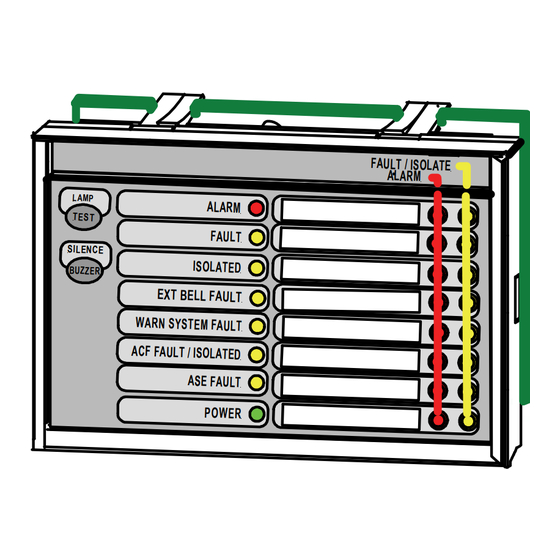
Description:
The LAM and IP40 housing is supplied assembled and
ready to be mounted to any flat surface.
Features:
Remote alarm & fault / isolate zone indication (8 zones)
Remote FACP status indication
Lamp test and buzzer silence controls
ZoneSense PLUS Max 8 LAM's per FACP (addresses
1-8)
Slip in label for Zone 1-8 or site specific information
(see LAB2656.DOC)
Programmed zones 1 (top) to 8 (bottom)
Installation:
Observe anti-static precautions at all times
1.
Power down the FACP, disconnect the batteries
Release of the Clip On Surround: Push down
here, pull out and lift up to remove and insert label.
DEFECT / ISOLATE
FIRE
Windows for
Slip in Label
Slip In Label
Figure 1: Inserting Optional Site Label
MAN2687-1
WORLD LEADER OF INNOVATIVE SOLUTIONS IN FIRE DETECTION AND ALARM SYSTEMS
Ampac Technologies Australia Tel: +61 8 9201 6100 Europe Tel: +44 (0) 1302 833 522 New Zealand Tel: +64 9 443 8072 www.ampac.net
LED Annunciator Master (LAM) NZS4512
Installation Guide
PCB
NOTE:
Lettering on slip in
label must be at
least 5mm in height.
Item Numbers: 4310-0038
2.
Open the front door and remove the four (4) screws
securing the front cover to the housing.
3.
Install an appropriate coupling into the housing
then mount using the three (3) knockout mounting
holes
4.
See Figures 1 and 2 if site specific label is to be
fitted
5.
Set the address (1 to 8) on the LAM as in Figure 2
6.
See Figure 3 for information on inserting the
termination link LK1 on the last card in the chain
7.
Reassemble
8.
Terminate the cabling from the FACP to the LAM
as shown in Figure 3
9.
Power up, connect the batteries and test
+
-
RS 485 IN FROM FACP
C O M
+
+ - SHLD
-
RS 485 OUT TO NEXT LAM
RS485
C O M
+24V
Field
PWR IN
0 V
Termination
in FACP
+24V
PWR OUT
+ -
0 V
AUX
24VDC
RS 485 IN FROM
+
PREVIOUS LAM
-
C O M
RS 485 OUT TO
+
NEXT LAM
-
C O M
+24V
P W R
IN
0 V
+24V
P W R
OUT
0 V
RS 485 IN FROM
+
PREVIOUS LAM
-
C O M
RS 485 OUT TO
+
NEXT LAM
-
C O M
+24V
P W R
IN
0 V
+24V
P W R
OUT
0 V
Figure 2: General Wiring of 3 LAM's
N1236
CN6
LAM 1
BUZZER MUTE INPUT
ADDRESS SWITCH
SET TO 1
LINK
TERMINATOR
LK1
NOT USED - ONLY USED ON THE LAST LAM IN
THE CHAIN REMOVE AND STORE AS SHOWN
CN6
LAM 2
BUZZER MUTE INPUT
ADDRESS SWITCH
SET TO 2
LINK
TERMINATOR
LK1
NOT USED - ONLY USED ON THE LAST LAM IN
THE CHAIN REMOVE AND STORE AS SHOWN
CN6
LAM 3
BUZZER MUTE INPUT
ADDRESS SWITCH
SET TO 3
LINK
TERMINATOR
LK1
ONLY INSERTED ON THE LAST CARD
Page 1
Advertisement

Related Manuals for Ampac NZS4512


Summary of Contents for Ampac NZS4512
- Page 1 Figure 2: General Wiring of 3 LAM's MAN2687-1 N1236 Page 1 WORLD LEADER OF INNOVATIVE SOLUTIONS IN FIRE DETECTION AND ALARM SYSTEMS Ampac Technologies Australia Tel: +61 8 9201 6100 Europe Tel: +44 (0) 1302 833 522 New Zealand Tel: +64 9 443 8072 www.ampac.net...
- Page 2 Figure 3: General Wiring Diagram MAN2687-1 N1236 Page 2 WORLD LEADER OF INNOVATIVE SOLUTIONS IN FIRE DETECTION AND ALARM SYSTEMS Ampac Technologies Australia Tel: +61 8 9201 6100 Europe Tel: +44 (0) 1302 833 522 New Zealand Tel: +64 9 443 8072 www.ampac.net...
Need help?
Do you have a question about the NZS4512 and is the answer not in the manual?
Questions and answers