Table of Contents
Advertisement
Quick Links
Advertisement
Table of Contents

Related Manuals for Ampac ZoneSense


Summary of Contents for Ampac ZoneSense
- Page 1 ZoneSense Fire Alarm Control Panel User Manual & Log Book EN54 2 & 4 MAN 2748-11...
- Page 2 Responding To An Alarm Access Level 1 (Normal Operation) 1. Indicators FIRE ZONE 1 ZONE 2 Zone FIRE Alarm Indicator - flashing FIRE Common FIRE Alarm Indicator – flashing 2. To Silence the FACP Buzzer SILENCE BUZZER Press 3. To Silence External Sounders Enter Access Level 2 – Key in Password - 3, 2, 1, 0 SILENCE ...
- Page 3 Disabling the Alarm Zone/s 1. Enter access Level 2 DISABLE / NEXT ENABLE Press Zone 1 Selected. Press to select Zone in FIRE DISABLE / ENABLE Then to Disable 2. To Disable Zone FIRE Alarm 3. Indicators ZONE 3 ZONE 4 Zone DISABLED Indicator –...
-
Page 4: Table Of Contents
TABLE OF CONTENTS Page No. About This Manual ....................... 1 Purpose ........................ 1 Scope........................1 References ......................1 Symbols ........................ 1 Introduction .......................... 2 Mechanical ..........................3 Locating the FACP ....................3 PCB Removal / Replacement ................3 Removing the Knockouts ..................3 Fixing the Chassis to the Wall ................ - Page 5 Calculating Standby Battery Capacity ................23 Trouble Shooting ........................ 24 Definitions .......................... 26 Glossary of Terms ......................27 Specifications ........................28...
-
Page 6: About This Manual
References This manual explains how to install and commission the ZoneSense FACP and should be read in conjunction with User’s Manual and Log Book that accompanies the panel. Documents related to the design, manufacture and installation of the ZoneSense FACP are;... -
Page 7: Introduction
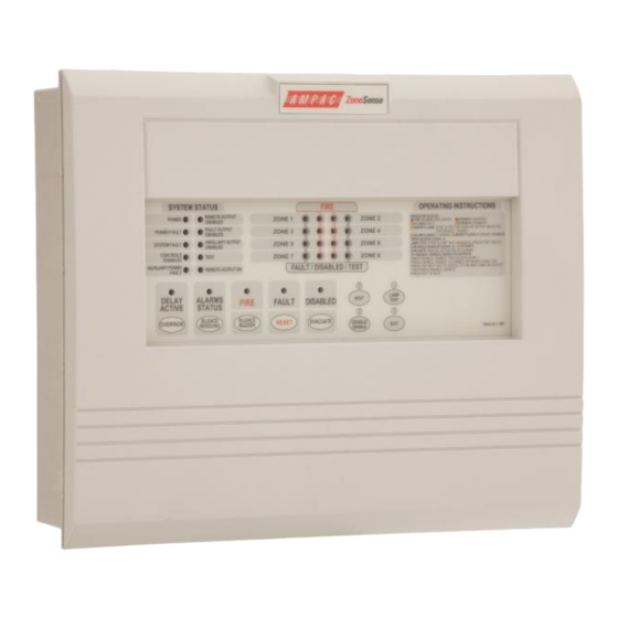
ZONESENSE EN54 INSTALLATION COMMISSIONING & OPERATION Introduction The ZoneSense Fire Alarm Control Panel (FACP) is supplied in an ABS (with a surround for recessed mounting) or metal cabinet as a two, four or eight zone Conventional FACP and can have up to four (4) remote LED Annunciator Cards (LAM’s) Order Code 43100-0037 and / or one (1) 8 Way Relay Board Order Code 4310-0050 [internal] 4310-0055 [external]. -
Page 8: Mechanical
ZONESENSE EN54 INSTALLATION COMMISSIONING & OPERATION Mechanical The ZoneSense FACP has an ABS (BX1) or Metal (BX10) enclosure that meets IEC529:1989 IP30 classification. The enclosure houses the Main Control Board (which has all the controls / indicators, power supply / battery charger circuitry mounted directly onto it), mains transformer and batteries. -
Page 9: Fixing The Chassis To The Wall
ZONESENSE EN54 INSTALLATION COMMISSIONING & OPERATION Fixing the Chassis to the Wall Refer to the diagrams of the panel showing a Typical FACP Layout. If necessary remove the batteries to expose the lower mounting keyhole. Taking into account the total weight of the panel securely mount it by using the three keyhole... - Page 10 ZONESENSE EN54 INSTALLATION COMMISSIONING & OPERATION 163.20 mm 147.00 mm 147.00 mm Figure 4: ABS (BX1) Mounting Points 230.90 mm 288.40 mm Figure 5: Metal Cabinet (BX10) Mounting Points Page 5...
-
Page 11: Electrical
ZONESENSE EN54 INSTALLATION COMMISSIONING & OPERATION Electrical Introduction The FACP consists of the Main Control Card and mains transformer. The control board is broken into two sections, the main control circuitry and the power supply / charger. FUSE BLOCK FRONT DOOR (REMOVED) 0.5A... -
Page 12: Power Supply
ZONESENSE EN54 INSTALLATION COMMISSIONING & OPERATION Power Supply The power supply equipment (PSE) consists of a primary power supply and battery standby if required. The primary power supply derives the appropriate voltages to run the FACP and charge the batteries (if fitted) from the available mains supply. In the event of a failure of the mains supply the PSE automatically switches over to the standby rechargeable sealed lead acid batteries to power the FACP. -
Page 13: Power Management
ZONESENSE EN54 INSTALLATION COMMISSIONING & OPERATION Power Management The following is the current requirements of the panel. Requirement Current Battery Charger 234mA 8 x Zones @ 25mA (in alarm) 200mA 8 x Zones @ 2mA (normal) 16mA 4 x Monitored Outputs (250mA each) -
Page 14: Connecting To And Operation Of The Main Control Board
ZONESENSE EN54 INSTALLATION COMMISSIONING & OPERATION Connecting to and Operation of the Main Control Board The Main Control Board provides a range of different field terminations – inputs, zone circuits, monitored outputs, voltage free outputs (relay), communications, open collector outputs and can include an optional controls enable front panel mounted key-switch. -
Page 15: Zone Circuits (Tb2 & Tb800)
ZONESENSE EN54 INSTALLATION COMMISSIONING & OPERATION Class Change (CC) Input I/P's C CC ALT Figure 10: TB1 Typical Class Change / Alert Input Termination & Location on the Main Control Card Zone Circuits (TB2 & TB800) A maximum of 32 x 24volt Optical / Heat Detectors and / or Manual Call Points mixed in any order can be fitted to each circuit. -
Page 16: Detector Removal Facility
ZONESENSE EN54 INSTALLATION COMMISSIONING & OPERATION Note: The activation of the remote output relay is not affected by the delay timer. Typically MCP’s must be fitted with series resistors (470 or 680 ohm), so as when the MCP is activated a short circuit is not present on the zone circuit. -
Page 17: Outputs - Open Collector (Tb4)
ZONESENSE EN54 INSTALLATION COMMISSIONING & OPERATION If the Alert input is ON, Class Change input is OFF, there are no zones in alarm and the front panel evacuate control is not active then the alarm outputs will pulse at the rate of 1sec ON and sec OFF. -
Page 18: Fault Output Relay
ZONESENSE EN54 INSTALLATION COMMISSIONING & OPERATION The output can also be disabled by using the front panel controls. Once disabled the relay will remain off until re-enabled and the front panel indicator “Remote Output Disabled” is illuminated. 6.12.2 Fault Output Relay The Fault Output Relay is energised if the FACP is operating normally and has unmonitored 1A 30VDC voltage free single change over contacts. -
Page 19: Enabling And Setting Delay Timing
ZONESENSE EN54 INSTALLATION COMMISSIONING & OPERATION 6.15 Enabling and Setting Delay Timing Note: Delay enabling and timing can only be set at access level 3 Enabling An 8 way DIP switch is used to enable the delays on a zone by zone basis. Switch 1 corresponds to zone 1;... -
Page 20: Summary Of Main Card Terminations
ZONESENSE EN54 INSTALLATION COMMISSIONING & OPERATION 6.17 Summary of Main Card Terminations Terminal Number Terminal Description Terminal Operation/Build Option COMMUNICATIONS EXTERNAL TB400 / 1 RS485 Used to connect to one 8 way relay card and up to four LAM’s RS485... -
Page 21: Facp Front Panel Controls And Indicators
ZONESENSE EN54 INSTALLATION COMMISSIONING & OPERATION FACP Front Panel Controls and Indicators The front panel consists of a 9 push buttons and 31 LED indicators, and an optional key-switch. Access Levels and Passwords By default the FACP is in access level 1. - Page 22 ZONESENSE EN54 INSTALLATION COMMISSIONING & OPERATION EOL Resistor Front of Main Card & Input Resistor Illustrated External Cabling Maximum of 32 Devices per Zone +24VDC / 100mA Class 15 Sec Resistor Change PROGRAMMING Capacitor Reset (CC) Input AND ACCESS Pulse...
-
Page 23: Ancillary Modules
ZONESENSE EN54 INSTALLATION COMMISSIONING & OPERATION Ancillary Modules Note: Ancillary modules are only supported in the 4 & 8 zone versions. The FACP has the ability to “learn” the type and address of connected ancillary modules. There is support for 1. -
Page 24: Led Annunciator Master (Lam) Card
ZONESENSE EN54 INSTALLATION COMMISSIONING & OPERATION LED Annunciator Master (LAM) Card LED annunciators (LAM’s); Are used to display fire system information at locations that are remote from the FACP. Have common FACP controls, status indicators, eight alarm and eight fault/disable/test indicators;... -
Page 25: Summary Of Typical Ancillary Board Specifications
ZONESENSE EN54 INSTALLATION COMMISSIONING & OPERATION 0VDC FAULT / DISABLED ZONE INDICATORS FIRE FAULT FIRE LAMP DISABLED TEST FIRE LAMP FIRE TEST FAULT FAULT DISABLED SILENCE DISABLED BUZZER ALARMS ALARMS STATUS STATUS SILENCE FIRE BUZZER OUTPUT FIRE OUTPUT STATUS STATUS... -
Page 26: Configuration
ZONESENSE EN54 INSTALLATION COMMISSIONING & OPERATION Configuration A label is fitted to all FACP’s so as the installer can record the configuration of the installation. ZONE ZONE TYPE TIME DELAY (min:sec)* NORMAL / DELAYED 0:00 0:30 NORMAL / DELAYED 1:00... -
Page 27: Compatible Devices
ZONESENSE EN54 INSTALLATION COMMISSIONING & OPERATION Compatible Devices Apollo Series 65 ORDER CODE Heat - A1R 55000-122 Heat – BR 55000-127 Heat – CR 55000-132 Heat – CS 55000-137 Smoke - Photo Optical 55000-317 Smoke – Ionisation 55000-217 Smoke – Integrating Ionisation... -
Page 28: Calculating Standby Battery Capacity
ZONESENSE EN54 INSTALLATION COMMISSIONING & OPERATION Calculating Standby Battery Capacity The minimum capacity of valve regulated lead acid batteries as recommended in BS 5839 – 1 : 2002 should be calculated using the following formula; Where;... -
Page 29: Trouble Shooting
ZONESENSE EN54 INSTALLATION COMMISSIONING & OPERATION Trouble Shooting If a Fault occurs on a critical part of the System, the Panel responds by activating its internal Buzzer and illuminating the common FAULT light and any other fault light(s) relating to the fault. The Panel's Fault Output will also activate (provided it has not been Disabled). - Page 30 ZONESENSE EN54 INSTALLATION COMMISSIONING & OPERATION may take several hours. If the batteries are in poor condition they must be replaced. Please note that the charging circuit is set up during manufacturing, and is temperature compensated. There is no need to adjust the voltage.
-
Page 31: Definitions
ZONESENSE EN54 INSTALLATION COMMISSIONING & OPERATION Definitions Addressable Device – an addressable input and/or output device. Alarm zone - the specific portion of a building or complex identified by a particular alarm zone facility. Alert signal - an audible signal, or combination of audible and visible signals, from the emergency warning system to alert wardens and other nominated personnel as necessary to commence prescribed actions. -
Page 32: Glossary Of Terms
ZONESENSE EN54 INSTALLATION COMMISSIONING & OPERATION Glossary of Terms ACF: ANCILLARY CONTROL FACILITY ALM: ALARM ANC: ANCILIARY AUX: AUXILIARY BATT: BATTERY RELAY COMMON CONTACT (WIPER) CONNECTOR CPU: CENTRAL PROCESSOR UNIT ETH: EARTH EOL: END OF LINE EVAC: EVACUATE FACP: FIRE ALARM CONTROL PANEL F.A.R.E:... -
Page 33: Specifications
ZONESENSE EN54 INSTALLATION COMMISSIONING & OPERATION Specifications Power Supply 204 to 264VAC 47 – 63 Hz Mains Supply Voltage Minimum Cable Requirements Not less than 1²mm Main Control Board Power Supply Set to 27.2VDC - Modulated: 27.2V with no alarm condition, with the battery fully charged and the ambient inside cabinet temperature is 25°C... - Page 34 UNCONTROLLED DOCUMENT NOTE: Due to AMPAC’s commitment to continuous improvement specifications may change without notice.
Need help?
Do you have a question about the ZoneSense and is the answer not in the manual?
Questions and answers