Advertisement
Quick Links
Advertisement

Related Manuals for Toshiba HSP100


Summary of Contents for Toshiba HSP100
- Page 1 Owner’s Manual HSP100 & HSP150 POS PRINTER POS PRINTER Model (TRST-P2 & TRST-P1) Revision 1.1...
- Page 2 WARNING! Changes or modifications made to this equipment, not expressly approved by TOSHIBA TEC or parties authorized by TOSHIBA TEC, could void the user's authority to operate the equipment. Toshiba America Business Solutions, Inc.
- Page 3 Do not attempt to effect repairs or modifications to this equipment. If a fault occurs that cannot be rectified using the procedures described in this manual, turn off the power supply, unplug the machine, and then contact your authorized TOSHIBA TEC representative for assistance. Meanings of Each Symbol This symbol indicates warning items (including cautions).
- Page 4 The cover should be cleaned by wiping with a dry cloth or a cloth slightly dampened with a mild detergent solution. NEVER USE THINNER OR ANY OTHER VOLATILE SOLVENT on the plastic covers. USE ONLY TOSHIBA TEC SPECIFIED paper. ...
- Page 5 BOTH ends of the cable. If another cable is used than described above you will need to test this cable with the TOSHIBA TEC printer and your system for local EMC requirements where the equipment is used.
- Page 6 Power Cord As the power cord is not supplied with this printer, locally purchase the power cord that meets the following standard. For USA and Canada: Power Cord – UL and CSA approved, type SVT, 18/3AWG, rated min. 125V, 10A Attached Plug and Appliance Coupler –...
- Page 7 Unpacking Open the carton. Remove the POS printer and the polyfoam out from the carton. Check the content and make sure no missing parts. Place the POS printer on a level surface and make sure no physical damage. POS Printer Quick Installation Starter Receipt Roll Manual...
- Page 8 TABLE OF CONTENTS Page 1. PRODUCT OVERVIEW ---------------------------------------------------- Introduction ----------------------------------------------------------------------- 1-1 Features --------------------------------------------------------------------------- Application Model --------------------------------------------------------------- Accessories ----------------------------------------------------------------------- 2. SPECIFICATIONS ----------------------------------------------------------- General ---------------------------------------------------------------------------- Environmental Usage Conditions ---------------------------------------------- 2-3 Internal Buffers ------------------------------------------------------------------- 2-3 Thermal Head Basic Performance --------------------------------------------- 2-4 Main Card ------------------------------------------------------------------------ Option Interface Card ----------------------------------------------------------- Reliability (TRST-P1 &TRST-P2) -------------------------------------------- 2.7.1 Life ------------------------------------------------------------------------...
- Page 9 6. DIAGNOSTICS ---------------------------------------------------------------- 6-1 Offline Diagnostic --------------------------------------------------------------- Main Menu ------------------------------------------------------------------------ Sub Menu ------------------------------------------------------------------------- 6.3.1 Setting Menu --------------------------------------------------------------- 6-3 6.3.2 Final Confirmation Menu ------------------------------------------------ Printer Configuration Form ----------------------------------------------------- 6-4 Maintenance Information Form ------------------------------------------------ 6-6 7. GENERAL MAINTENANCE ---------------------------------------------- Cleaning the Covers ------------------------------------------------------------- Cleaning the Thermal Print Head ---------------------------------------------- 8.
- Page 10 CAUTION! 1. This manual may not be copied in whole or in part without prior written permission of TOSHIBA TEC. 2. The contents of this manual may be changed without notification. 3. Please refer to your local authorized service representative with regard to any queries you may have in...
- Page 11 1. PRODUCT OVERVIEW 1.1 Introduction Thank you for purchasing the TOSHIBA TEC TRST-P1 (180dpi) / TRST-P2 (203dpi) Series POS Printer. This product is a single station POS printer, which consists a thermal head for one side printing. Base model includes 32bit CPU architecture with Flash ROM, Cash Drawer Connector, Mini-DIN Power, USB Type A and Type B connector.
- Page 12 1. PRODUCT OVERVIEW 1.3 APPLICABLE MODEL 1.3 Applicable Model Model name description T R S T - P X X X - X X - X X - S S: ROHS2 Compliant Destination QQ: US QM: GLOBAL (Worldwide) Color 1B: Black Interface N : Standard interface (USB A/B) 02: Ethernet interface option...
- Page 13 1.4 Accessories Confirm that the following accessories are contained in the carton. If any accessories are missing or damaged, contact your TOSHIBA TEC service representative. The following accessories are packed in the shipping carton box as shown below: Printer enclosed in a plastic bag and foam pack...
- Page 14 2. SPECIFICATIONS 2.1 GENERAL 2. SPECIFICATIONS 2.1 General Resolution TRST-P1(180 dpi model): 180 dpi x 180 dpi (7 dots/mm) TRST-P2 (203 dpi model): 203 dpi x 203 dpi (8 dots/mm) Interface (USB Type-B) USB 2.0 High Speed Printer Class Interface (USB Type-A) USB High Speed Mass storage class File format supported: FAT12,FAT16,FAT32, VFAT...
- Page 15 2. SPECIFICATIONS 2.1 GENERAL Printable Width 80mm Paper mode 58mm Paper mode - SBCS Font A 576 dots (72.00 mm) 408 dots (51.00 mm) 576 dots (72.00 mm) 396 dots (49.50 mm) - SBCS Font B - SBCS2 Font A 546 dots (68.25 mm) 390 dots (48.75 mm) 560 dots (70.00 mm)
- Page 16 2. SPECIFICATIONS 2.2 ENVIRONMENTAL USAGE CONDITIONS 2.2 Environmental usage conditions 1) During normal operation Temperature range : 5 - 50°C Temperature change : Max. 10°C /hour Humidity range (no condensation) : 5% - 90% Temperature at dew point : Max. 26°C Humidity change : Max.10% /hour (at 26°C) 2) In idle mode...
- Page 17 2. SPECIFICATIONS 2.4 THERMAL HEAD BASIC PERFORMANCE 2.4 Thermal head basic performance TRST-P1 (180dpi model) 1) Type : Line thermal 2) Number of heating elements : 512 dots 3) Dot density : 7 dots/mm 4) Effective recording width : 72.25 mm 5) Data transmission method : 2 serial I/O inputs.
- Page 18 2. SPECIFICATIONS 2.7 RELIABILITY (TRST-P1 &TRST-P2) 2.7 Reliability (TRST-P1 &TRST-P2) 2.7.1 Life Thermal print head : 200 km (based on specified paper NPI TF50KS-EY) Cutter : 2 million cuts (based on specified paper NPI TF50KS-EY) 2.7.2 Life MTBF (MCBF) Printer : 65,000,000 Lines* (MCBF) MAIN PCB : 1,650,000 hours (Telcordia RPP, formerly Bellcore)
- Page 19 Powered USB connector Power Adapter This Power Adapter is for the exclusive use for the TRST-P1N-1B-QQ-S and TRST-PC04-QQ-S TRST-P2N-1B-QQ-S TOSHIBA TEC POS printer. Serial Interface Serial Interface is used to transmit data TRST-PC03-QQ-S from the network to your computer by using RS232 cable.
- Page 20 A contact of chemical or oil may discolor or erase the printed record. Rubbing the paper hard with nail or hard object may discolor the paper. The paper end should not be pasted to the core. For further information please contact your authorized TOSHIBA TEC representative or authorized paper manufacturer.
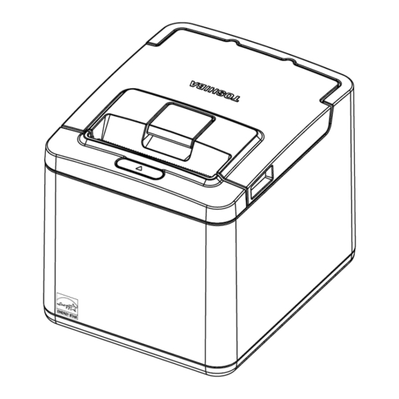
- Page 21 3. APPEARANCE 3.1 FRONT/REAR VIEW 3. APPEARANCE 3.1 Front/Rear View Front View Rear View Cover Main Cover Cover Open LED and Feed Lever Button Front Cover — Open this cover to load paper • Top Cover Cover Open Lever — Lift this lever to open top cover •...
- Page 22 2. To the DC24V connector (Power connector), do not connect anything other than the TOSHIBA TEC recommended power adapter. 3. The TOSHIBA TEC recommended power adapter be exclusively for this printer. Do not use it for any other machines. 1. [DC24V] (Power connector) The external power adapter supplies +24V power to the printer through this connector.
- Page 23 3. APPEARANCE 3.4 SPECIFICATION OF INTERFACE & POWER CONNECTOR 3.4 Specification of Interface & Power Connector 3.4.1 RS232 Interface RS232 Option I/F is transmitted through the full duplex serial port. The specification is as follows. 1) Baud Rate : 115200, 57600, 38400, 19200, 9600 bps 2) Data transfer protocol : DTR/DSR or XON/XOFF 3) Parity Bits...
- Page 24 3. APPEARANCE 3.4 SPECIFICATION OF INTERFACE & POWER CONNECTOR 3.4.3 USB Interface USB I/F is mounted on main card as default. There are 2 ports. 1st port is for Host function with Type A connector and 2nd is for Device function with Type B connector. It does not support USB host port and device port at the same time.
- Page 25 3. APPEARANCE 3.4 SPECIFICATION OF INTERFACE & POWER CONNECTOR 3.4.5 Cash Drawer Connector and Pin Assignments The Cash drawer connector is located at the rear of the printer. The Cash drawer connector is a 6–pin modular type connector with the following pin assignments:...
- Page 26 4. SET UP PROCEDURE 4.1 REQUIREMENT FOR OPERATION 4. SET UP PROCEDURE 4.1 Requirements for Operation This printer needs the following requirements for communication and power: Serial Interface Type The POS terminal to be connected must have a Serial port. To communicate with the POS terminal, an RS232 interface cable is required.
- Page 27 4. SET UP PROCEDURE 4.2 SETTING UP THE PRINTER 4.2 Setting up the Printer CAUTION! 1. Place the printer on a flat, stable surface. 2. Do not place the printer close to a heater or where it may be exposed to direct sunlight. 3.
- Page 28 Do not connect the power cord to the AC outlet provided on the POS terminal. CAUTION! When separating the power adapter, please contact your authorized TOSHIBA TEC representative. The recommended power adapter is exclusively for this printer. Do not use it for any other machines.
- Page 29 5. INSTALLATION PROCEDURE 5.1 CONNECTING THE POWER CORD AND INTERFACE CABLE 5.1 Connecting the Power Cord and Interface Cable CAUTION! Be sure to hold the connector when plugging in or unplugging the power adapter cable. Insert the power adapter cable and the power cord firmly. 5.1.1 Remove and attach Cable Cover Remove the cable cover before connecting all the interface cables.
- Page 30 5. INSTALLATION PROCEDURE 5.1 CONNECTING THE POWER CORD AND INTERFACE CABLE 5.1.4 Connect via Option Card (RS232 & LAN) Remove the screw to detach the option metal cover in order to install the option cards. Remove the other screw also as this will be used to secure the option assembly. Option metal cover Screw...
- Page 31 [Drawer interface connector] (6-pin modular connector) A Drawer cable which connects the printer to a drawer is connected to this connector. To this connector, a TOSHIBA TEC drawer can be connected. Further information please refer to Section 3.4.5 “Cash Drawer Connector and Pin Assignments”.
- Page 32 5. INSTALLATION PROCEDURE 5.1 CONNECTING THE POWER CORD AND INTERFACE CABLE 5.1.7 Interface cable to POS terminal connection position Connect the interface cable to the POS terminal, and then plug in the power cord to the AC outlet. LAN (Left) Y-cable and USB Inlet...
- Page 33 5. INSTALLATION PROCEDURE 5.2 CHOOSING A LOCATION 5.2 Choosing a Location Table Top – Horizontal orientation The POS printer takes up relatively little counter space and may be set on or near the POS terminal. Make sure that there is enough room to open the receipt cover for changing the paper roll. The paper will be presented in the top exit direction.
- Page 34 5. INSTALLATION PROCEDURE 5.2 CHOOSING A LOCATION 3. Wall Mounted – Vertical orientation CAUTION! The wall mounting printer must be installed by a qualified and professional installer who is familiar with building construction methods, building materials, building codes, electrical codes, fire codes, and local laws governing public access areas.
- Page 35 5. INSTALLATION PROCEDURE 5.2 CHOOSING A LOCATION This guide can be printed out in A4 size as a reference for the wall mount. Since printing A4 paper settings may vary across different printers, please measure and ensure the distances are the same as the dimensions stated before drilling the wall.
- Page 36 5. INSTALLATION PROCEDURE 5.3 LOADING THE RECEIPT ROLL 5.3 Loading the Receipt Roll When you use the printer for the first time or when the receipt paper has been used up, load a receipt roll following the procedures while the printer power is still connecting to power supply and is set to A POS printer prints thermal receipt paper by applying heat to the paper to react with the chemicals on the paper surface.
- Page 37 5.3 LOADING THE RECEIPT ROLL CAUTION! 1. Use only TOSHIBA TEC specified paper. Use of non-specified paper may shorten the print head life resulting in problems with print quality, paper feed failure, or shorten the cutter life. 2. Do not subject the thermal receipt roll to water, oil, or heat source as this will darken the paper.
- Page 38 5. INSTALLATION PROCEDURE 5.3 LOADING THE RECEIPT ROLL Close the printer top cover gently and printer will automatically perform auto cut. Horizontal Orientation Vertical Orientation Installing 58 mm paper guide (Sold separately) To enable 58 mm print width, refer to 6.3 Sub Menu, select “Paper Width” and select 58 mm. Insert the 58 mm paper guide to the slots located inside the left side of the printer.
- Page 39 6. DIAGNOSTICS 6.1 OFFLINE DIAGNOSTIC 6. DIAGNOSTICS 6.1 Offline Diagnostic While the printer cover is open, press and hold the feed button until the printer beeps once. Close the cover and the printer prints the configuration form. Press feed button by a short press to enter offline diagnostic mode or press it long to exit to online mode.
- Page 40 6. DIAGNOSTICS 6.3 SUB MENU 6.3 Sub Menu Once a menu to change a setting is selected in main menu, it prints sub menu as follows. This menu is to select an item to change a setting by pressing the feed button by a short press followed by a long press for 3 seconds and release according to the menu guideline.
- Page 41 6. DIAGNOSTICS 6.3 SUB MENU 6.3.1 Setting Menu Once an item to change a setting is selected in, it prints setting menu as follows. This menu is to select a setting option of each setting by clicking the feed button followed by long press according to the menu guideline.
- Page 42 6. DIAGNOSTICS 6.4 PRINTER CONFIGURATION FORM 6.4 Printer Configuration Form Printer Configuration Form indicates the individual information including its configurations. Operations to print Printer Configuration Form are as follows. 1. The cover is closed after the printer beeps once. 2. “To Print Config. Form” in offline diagnostic is chosen 3.
- Page 43 6. DIAGNOSTICS 6.4 PRINTER CONFIGURATION FORM When Ethernet interface card is inserted to the printer, the following information is shown. Ethernet Interface Settings MAC address : xx.xx.xx.xx.xx.xx IP address : 192.168. 1. 99 Subnet Mask : 255.255.255. 0 Default Gateway : 0.
- Page 44 6. DIAGNOSTICS 6.5 Maintenance Information Form 6.5 Maintenance Information Form Maintenance Information consists from two 2D barcode that include various information related to the maintenance. (QR CODE is for references ONLY) Operations to print Maintenance Information are as follows. “To Print Maintenance Info.” in Offline Diagnostic is chosen “Print Maintenance Information Form”...
- Page 45 7. GENERAL MAINTENANCE 7.1 CLEANING THE COVERS 7. GENERAL MAINTENANCE WARNING! Be sure to disconnect the power cord prior to performing any maintenance. DO NOT POUR WATER directly onto the printer, as this may cause electric shock or fire. The print head becomes very hot while printing. To avoid getting burned, never touch the print head during the maintenance.
- Page 46 WARNING! If you cannot solve a problem with the following solutions, do not attempt to repair it by yourself. Turn the power supply off, unplug the printer, and then contact your authorized TOSHIBA TEC representative for assistance. 8.1 Removing Jammed Paper 1) When printer is jammed, the LED will show AMBER color with one blinks and Pause for 5seconds.
- Page 47 8. TROUBLESHOOTING 8.1 REMOVING JAMMED PAPER 4. Flip to open the top cover. 5. Remove any jammed paper and paper roll out from the printer. DO NOT USE any sharp implement or tool as these will damage the printer. Close the printer top cover A first. Then, close the printer front cover B. The printer cutter will reset to the original position 7.
- Page 48 8. TROUBLESHOOTING 8.3 COMMON PROBLEMS & SOLUTIONS 8.3 Common Problems & Solutions Power Supply Failure Phenomenon Cause Check method Solution No power is supplied. The power adapter DC Check if the cable is Connect the specified (Power LED does not cable is not connected to connected properly.
- Page 49 Check the setting in the Make sure the function is enabled in function is not enabled POS terminal the POS terminal. in POS terminal NOTE: If any problem occurs other than the above, please contact your authorized TOSHIBA TEC representative.
- Page 50 NOTE: If other LED status except for the above occurs, turn the power supply off, and then reopen. If this does not restore the LED, contact your nearest TOSHIBA TEC representative for assistance .
- Page 51 9. APPENDIX 9.1 ETHERNET 9. APPENDIX 9.1 Ethernet Ethernet interface is available when Ethernet option card is connected to printer. 9.2 Password Registration The printer rejects all data / commands via Ethernet interface unless an end user specifies their own password of Web setting However, even if the password is not properly specified yet, it is able to Links-Up.
- Page 52 9. APPENDIX 9.3 WEB SETTING PAGE 9.3 Web Setting Page Printer supports setting change via web page. It requires “User name” and “Password” to login web setting page. IP Address : IP address for DHCP “Disable” Subnet mask : Subnet mask setting ...
- Page 53 SNMP : “Enable”, “Disable” SNMP functionality. Read/Write : Community name for SNMP. TRAP 1 : “Enable” “Disable” for TRAP 1. IP address : IP address for Trap 1 Community name : Community name for Trap1 ...
Need help?
Do you have a question about the HSP100 and is the answer not in the manual?
Questions and answers