Toshiba B-SA4T Series Manual
Also See for B-SA4T Series:
- Option installation manual (58 pages) ,
- Product description (45 pages) ,
- Printer driver operating manual (105 pages)
Advertisement
Table of Contents
Contents
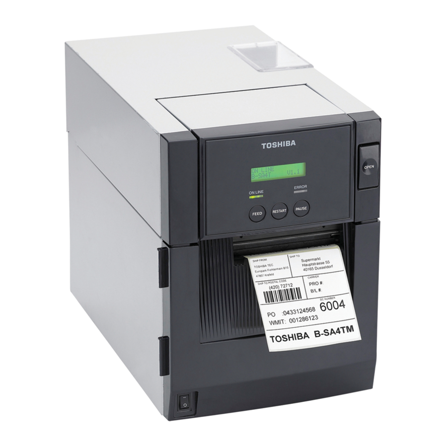
Toshiba B-SA4T Series Manual
INSTALLATION PROCEDURE FOR OPTIONAL EQUIPMENT

- Turn the printer power off and disconnect the power cord before installing an optional equipment.
- Be careful not to pinch your fingers or hands with the covers.
- Be careful not to injure your fingers when installing the cutter module.
Cutter Module: B-SA204-QM/B-SA204-QM-R

Do not connect/disconnect the cutter harness to/from the printer within one minute from a power off to protect the internal electrical circuit of the printer.
- Packing List
The following parts are supplied with the kit. Make sure you have all items shown below.
![]()

- Installation Procedure
- Open the Front Cover, and remove the B-3x6 screw to detach the Connector Cover.


- Open the Front Cover wider. Remove the Front Cover by lifting it to disengage the hinge pins from the hinge. The Front Cover cannot be removed unless it is opened at an angle of over 100 degrees as the stoppers of the hinge prevent disengagement.


- Mount the Cutter Module Cover by inserting the hinge pins into the hinges.


- Fit the Cutter Unit to the front of the printer by inserting the Hinge Pins into the Hinge Pin Holes.


- Connect the Cutter Harness to the connector at the front of the printer.


- Close the Cutter Unit and secure it to the printer with the Set Screw.


- Close the Cutter Module Cover.


- Media loading procedure - Owner's Manual
- Operation check - Owner's Manual
- System mode setting - System Mode Manual
- Cleaning - Owner's Manual
Strip Module: B-SA904-H-QM-R
- Packing List
The following parts are supplied with the kit. Make sure you have all items shown below.
![]()

- Installation Procedure
- Open the Top Cover and the Front Cover. Remove the B-3x6 screw to detach the Connector Cover.


- Open the Front Cover wider. Remove the Front Cover by lifting it to disengage the hinge pins from the hinge. The Front Cover cannot be removed unless it is opened at an angle of over 100 degrees as the stoppers of the hinge prevent disengagement.


- Mount the Strip Module Cover by inserting the hinge pins into the hinges.


- Fit the Shaft Holders of the Backing Paper Feed Roller into the cuts of the printer.


- Secure the Strip Unit to the printer with the two screws. Make sure that the Feed Roller Gear rotates smoothly.


- Close the Strip Unit.


- Secure the Ground Wire to the printer and the Strip Unit, as shown in the picture below.


- Connect the Strip Harness to the connector at the front of the printer.


- Close the Strip Module Cover. Perform an operation check for a proper strip issue.
![]()

- Media loading procedure - Owner's Manual
- Operation check- Owner's Manual
- System mode setting- System Mode Manual
- Cleaning - Owner's Manual
Wireless LAN Module: B-SA704-WLAN-QM
- Packing List
The following parts are supplied with the kit. Make sure you have all items shown below.
![]()

 NOTES:
- DO NOT CHANGE the DIP Switch settings on the Wireless LAN Board. Doing so may cause a malfunction.
- MAC address of the Wireless LAN module will be necessary when setting the MAC address filtering function of an access point. As it is printed on the top of the wired LAN connector on the Wireless LAN Board, write down it on Installation Manual before mounting the covers so that an end user can know the MAC address.
- Be careful not to hit or damage the antenna when installing this kit. A damaged antenna may affect the performance.


- Installation Procedure
- Remove the two SMW-3x6 screws from the back of the printer.


- Open the Top Cover and Front Cover.


- Remove the two SMW-3x6 screws which secure the Side Panel.


- Close the Front Cover and remove the Side Panel.


- Remove the two SMW-3x6 screws to detach the Blind Plate.


- Remove the SMW-3x8 screw to detach the Cable Clamp.


- Put the Antenna of the Wireless LAN Board out of the opening in the printer back. Care must be taken not to hit the Antenna against the printer frame, as damaged antenna may affect the performance.


- As the following picture shows, secure the Wireless LAN Board to printer back with the two of the enclosed SMW-3x6 screws. Also, secure the Wireless LAN Board to the PCB Support Plate with the SMW-3x6 screw, together with the Cable Clamp removed in Step 6.


- Connect the Wireless LAN Power Cable and the LAN Cable as shown below.


- Fit the Antenna Cover to the back of the printer. Secure it with the SMW-3x6 screw.


- Re-attach the Side Panel to the printer.
- Country Code
As available frequency bands are different from country to country, be sure to set a country code before installing a wireless LAN module in a user's printer. Also, ask an end user to confirm a country code. Use of a wireless LAN module with a wrong country code could violate each country's Laws and Regulations for Radio Equipment, and violators could be subject to penalties. The country code cannot be changed through the Web browser, but TELNET.
<How to set a country code using TELNET>
! The following information must not be disclosed to users. (Internal use only) (
- Disconnect the LAN cable connected to the printer, connect the printer to a host PC with a straight LAN cable via a relay connector. When using a hub in place of a relay connector, use a cross cable or
- Open the MS-DOS prompt, type in "telnet 192.168.10.21" (default IP address).
- Enter a password to log in. (Password: tecbcp)
- From the top menu, change a country code using the following command. =>ctry XX (XX=new country code. See Country Code Table.)
- The new country code will become effective by turning the printer off and on again.
- A country code can be checked by typing "=>ctry" on the telnet console.
<Country Code Table>
| Country code | Country name | Country code | Country name | Country code | Country name |
| US | U.S.A./Canada | GR | Greece | IE | Ireland |
| FR | France | SE | Sweden | GB | U.K. |
| PT | Portugal | HU | Hungary | AU | Australia |
| NO | Norway | BE | Belgium | FI | Finland |
| DE | Germany | IT | Italy | LU | Luxembourg |
| ES | Spain | NL | Netherlands | CH | Switzerland |
| IS | Iceland | LI | Liechtenstein | NZ | New Zealand |
| AT | Austria | DK | Denmark |
Regarding various settings or operation check for the wireless LAN, refer to the System Mode Manual.
Serial Interface Board: B-SA704-RS-QM-R
- Packing List
The following parts are supplied with the kit. Make sure you have all items shown below.
![]()

- Installation Procedure
- Remove the two screws from the back of the printer.


- Open the Top Cover and Front Cover.


- Remove the two SMW-3x6 screws which secure the Side Panel.


- Close the Front Cover and remove the Side Panel.


- Remove the two screws to detach the Blind Plate.


- Attach the enclosed PCB Support Plate to the printer back with one of the enclosed SMW-3x6 screws.


- Fit the Locking Support into the MAIN PC Board.


- Connect the Serial Interface Cable of the SIO PC Board to CN12 on the MAIN PC Board.


- Secure the SIO PC Board to the printer back with the two SMW-3x6 screws. Fit the Locking Support into the SIO PC Board.


- Re-attach the Side Panel.
Documents / ResourcesDownload manual
Here you can download full pdf version of manual, it may contain additional safety instructions, warranty information, FCC rules, etc.
Advertisement


Need help?
Do you have a question about the B-SA4T Series and is the answer not in the manual?
Questions and answers