Table of Contents
Advertisement
Quick Links
Dantec
Keypoint
G4
®
®
User and Service Guide
Part Number: 9031M1506 Rev F
23/NOV/2022
System Model Number: 9031A0701
© 2016 - 2022 Natus Medical Incorporated or one of its subsidiaries. All rights reserved. Natus is a registered trademark of Natus Medical
Incorporated. All product names appearing on this document are trademarks or registered trademarks owned, licensed to, promoted or
distributed by Natus Medical Incorporated, its subsidiaries or affiliates. All other trademarks are the property of their respective owners.
Advertisement
Table of Contents

Related Manuals for natus Dantec Keypoint G4


Summary of Contents for natus Dantec Keypoint G4
- Page 1 System Model Number: 9031A0701 © 2016 - 2022 Natus Medical Incorporated or one of its subsidiaries. All rights reserved. Natus is a registered trademark of Natus Medical Incorporated. All product names appearing on this document are trademarks or registered trademarks owned, licensed to, promoted or...
-
Page 2: Contact Information
This copy of the User Manual shall be used only in accordance with the conditions of sale of Natus Medical Incorporated or its distributors, including without limitation the Natus Software License Agreement. Natus Medical Incorporated makes no representations or warranties of any kind whatsoever with respect to this document. -
Page 3: Glossary Of Symbols
Glossary of Symbols The following labels and symbols may be affixed to the Dantec Keypoint G4 system: Symbol Title as Symbol Standard Reference Standard Title of Symbol per Referenced Explanation Standard Medical devices — Symbols to be used with ISO 15223-1... - Page 4 Symbol Title as Symbol Standard Reference Standard Title of Symbol per Referenced Explanation Standard Medical devices — Indicates the Symbols to be used with manufacturer’s catalogue ISO 15223-1 information to be Catalogue number number so that the supplied by the Symbol 5.1.6 medical device can be manufacturer —...
- Page 5 Symbol Title as Symbol Standard Reference Standard Title of Symbol per Referenced Explanation Standard Indicates that electrical and electronic equipment Waste Electrical and Disposal at end of waste should not be Directive 2012/19/EU Electronic Equipment operating life discarded together with (WEEE) instructions unseparated waste but...
-
Page 6: Table Of Contents
Table of Contents Contact Information ..............................2 Glossary of Symbols ..............................3 Table of Contents ..............................6 General Information ............................... 9 User Guide ................................9 Intended Use ..............................9 System Overview ..............................9 Clinical Performance ............................9 Clinical Benefits ..............................9 Medical Conditions ............................. - Page 7 Models: 9031D040x / 9031D041x ........................ 19 Isolation Transformer Classification ......................20 Control Panel ..............................21 Control Functions.............................. 21 Software Navigation / Software Functions ....................21 Sweep Speed / Sensitivity Level ........................22 Stimulation ..............................22 Stimulus Intensity / Duration / Repetition Rate ................... 22 Loudspeaker / Volume / Cursor Mode / Trace / Marker / Trigger ...............
- Page 8 Safety Inspection Checks ........................... 51 Troubleshooting Noisy Data ..........................51 Cleaning Instructions ............................52 Disposal at End of Operating Life Instructions ....................52 Natus Technical Support Contact Information ....................53 Electromagnetic Compatibility (EMC) ........................54 Maintaining ..............................54 EMC Acceptance Criteria ..........................54 Deviations from collateral standard .........................
-
Page 9: General Information
A PDF copy of this user guide is available on the USB drive provided with the Dantec system. Copies of the user guide may also be accessed at natus.com in the Support section. Scroll to the EMG Product IFUs, select Dantec Keypoint G4 and choose the version for your local language. -
Page 10: Patient Population And Target Group
Patient Population and Target Group The Keypoint G4 assists the physician in the diagnosis of patients with neuromuscular diseases for pediatric and adult patients. Residual Risks and Side Effects There are no known residual risks or side effects for procedures performed with the Keypoint G4. Please note the Warnings and Cautions before applying power to and using the system. -
Page 11: Ancillary Accessories
Ancillary Accessories To facilitate the acquisition of electrophysiological information using this system, there are ancillary accessories that must be used. These accessories include surface electrodes and needle electrodes that are not included with the system. To ensure proper use of the system; descriptions, recommendations and or specifications are provided for these ancillary accessories that are deemed compatible with the Keypoint G4 system. -
Page 12: Safety, Warnings And Precautions
Caution damage to the device. Any serious incident that has occurred in relation to the Natus Keypoint G4 system be reported to the manufacturer and the competent authority of the Member State in which the user and/or patient is established. -
Page 13: Cautions
Avoid accidental contact between connected, but unapplied electrodes and other conductive parts - including those connected to protective earth. Always use shielded power line cables from Natus to avoid hum line interference, especially near the patient, or the amplifier. Cautions... -
Page 14: Safety Requirements
The device must be disconnected from all voltage sources before being opened for any adjustment, replacement, maintenance or repair. • Service must be referred to Natus authorized service personnel, except for such works described in this manual as being performed by the operator. •... -
Page 15: Excerpt From The Iec 60601-1 Standard
Method(s) of cleaning recommended by the manufacturer: • Please see Maintenance and Cleaning. Degree of protection against electric shock: • Type BF: applied part providing a particular degree of protection against electric shock, particularly regarding: • Allowable leakage current • The applied part is electrically isolated (floating). -
Page 16: Stimulation Pulse Terminology
Electrode Areas 9031E017 = 0.58 cm 9013L036 = 0.39 cm ���� 2�������� ���� = √2 × 0.0002 × < An example: 9013L036 surface stimulation electrode, felt tips, stimulus frequency 2 Hz, pulse width 0.2 ms: 0.39�������� �������� ���� < 39�������� Stimulation Pulse Terminology The term “pulse duration”... -
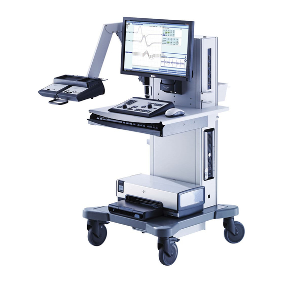
Page 17: System Hardware
System Hardware This chapter describes the basic hardware used to operate the Dantec Keypoint G4 system. Workstation 1 Computer Amplifier Box (optional) 2 Power Switch Connection Panel 3 Monitor Accessory Box Kit (optional) 4 Internal Speaker Mouse 5 Control Panel... -
Page 18: Cable Connection Overview
Cable Connection Overview Power Supply / Isolating Transformer Screen Loudspeaker Printer (optional) Amplifier Box (optional) Network Isolator (optional) Computer Stimulator Box (optional) Cart Enclosure DC power supply unit (used with PC Keyboard Mouse Isolating Transformer) Control Panel Connection Panel EP Amplifier Box (optional) Cable Connections Before operating the device, the system parts should be connected. -
Page 19: Connection Panel
Function Description Mains Input Plug the shielded mains power cord supplied with the system into this socket. NOTE Only use a shielded power cord from Natus. Rating Frequency: 50/60Hz. - Continuous Operation: max. 1000VA - Momentary Operation: max 1500VA 9031D040x: 100/120V~... -
Page 20: Isolation Transformer Classification
Function Description Fuse F1 and F2 Mains 9031D040x: 110V/120V: T10A / 250V~ 9031D041x: 200/240V: T6.3A / 250V~ M4 Thread for Electrical Enclosure Contact and Additional Protective Earth. Potential equalization Where potential equalization is necessary or desirable, a potential equalization conductor may be connected to this connector as per DIN 42 801. -
Page 21: Control Panel
Control Panel Standby Indicator Stimulation Indicator Power ON Indicator Single Stimulation Key Numeric Keypad Repetitive Stimulation Key Software Navigation Keys Trace/Marker and Trigger Arrow Keys Sweep Speed/Sensitivity Level Arrow Keys Volume Indicator Stimulation Intensity Control Knob Volume/Cursor Control Knob Reset Stimulation Intensity Key Cursor Mode Indicator Stimulation Duration Arrow Keys Loudspeaker Mute Key / Indicator... -
Page 22: Sweep Speed / Sensitivity Level
Sweep Speed / Sensitivity Level Sweep Speed Arrow Keys The Right and Left arrow keys allows modification of the sweep speed. The Right arrow key increases the sweep speed. The Left arrow key decreases the sweep speed. Sensitivity Level Arrow Keys The Up and Down arrow keys allows modification of the level of sensitivity. -
Page 23: Loudspeaker / Volume / Cursor Mode / Trace / Marker / Trigger
Loudspeaker / Volume / Cursor Mode / Trace / Marker / Trigger Loudspeaker Mute Key / Indicator Press the Loudspeaker Mute key to switch between the On and Off function. The yellow light (LED) indicates the loudspeaker is muted. To adjust the volume, see the Control knob function below. Volume Indicator The green light (LED) indicator is on when the volume function is enabled –... - Page 24 3 Channels 4 Channels 6 Channels 8 Channels Power ON Indicator The green light (LED) indicates that the amplifier power is On. Amplifier Input (isolated) All amplifier input connectors are electronically isolated. Electrostatic Sensitive Amplifier Input Connectors WARNING Do not touch the Amplifier Input connectors as it may damage the amplifier or affect its performance. Impedance Test Key / Indicator (4/6/8 channels only) Ω...
-
Page 25: Rear Panel
Patient Ground Connector / Indicator Connect the patient's ground electrode to the green connector. The green light (LED) indicates the results of the impedance test. –See the LED Status and Results description under the Active Electrode Indicator. Patient Ground Connector / Indicator Connect the patient's ground electrode to the green connector. -
Page 26: Stimulators
Amplifier Input Connectors – Common Array The green light (LED) indicates the results of the impedance test as described below. LED Status Result All LEDs Off Acceptable Impedance Constantly lit LEDs High Impedance Amplifier Input Connectors – Head Array (Montage) The head array electrode connectors are labeled according to the International 10-20 System of Electrode Placement. -
Page 27: Buttons 5 And 6
Start/Stop Averager – Active in Sensory Nerve testing Briefly press the button on the handle. Run train – Active in F wave Briefly press the button on the handle New Site Button – Active in Motor and Sensory Nerve testing Briefly press the button on the handle. -
Page 28: Stimulation Electrodes
CC Stimulator Output (isolated) CC stimulator output connectors are electronically isolated. Stimulus Release Indicator Flashes for the stimulation pulse. CC Stimulator Output Socket (isolated) For connection of stimulation electrodes with DIN plugs. Support for the active handgrip. Touch-proof Output Connectors (isolated) For connection of stimulation electrodes with touch-proof connectors. -
Page 29: Power Up Test
Pedal Function Application dependent. Refer to Natus Probe, Button 5 for function descriptions below. Start/Stop Stimulation Press down for 1 second to start repetitive stimuli. Run/Pause – Application dependent. Refer to Natus Probe, Button 6 for function descriptions below. Power Up Test At start up, hardware status is provided on the Home page. -
Page 30: Additional Keypoint G4 Accessories And Software Options
Natus Tubal Insert Phones 9033B0332 P300 Reaction Time Switch 9031E0223 Natus LED Goggles with 5m cable 9031F1124 Natus Pattern Stimulator 22" TFT Display with Connection Kit 9031B0521 Amplifier Arm, Single 9031B0511 Amplifier Arm, Dual 9033B0761 Flex Arm with Clamp, 40cm... -
Page 31: System Operation
System Operation This chapter provides a detailed description of Keypoint.NET software operations. Starting Dantec Keypoint.NET To start the application, double-click the Keypoint.NET icon located on the Microsoft Windows desktop. The Home Page will then be displayed. Home Page The Home Page is the start view when the program opens. From the Home Page the following options are available: Create a New Study. -
Page 32: New Study - Patient Data
New Study - Patient Data Clicking the New Study button in the Home page opens the Patient Data page. From the Patient Data page enter/edit: Patient data • • Comments • Conclusions Memo 1, 2, 3 • • Notes (read only) Note that data cannot be entered when the Study Complete check box is selected. - Page 33 Status Icons Status icons are displayed in the first two columns indicating the status of each study. Icons include the following: Uploading Local Completed Checked out Active Remote New Study for this Patient To create a new study for the patient, click New Study for This Patient to be directed to the Patient Data page. Patient information is retrieved in patient data, and may be edited.
-
Page 34: Test Menu
Test Menu Top navigation bar with tabs Anatomy box Application Setting Selection Test type view Left or right option buttons Patient status bar Filter root drop-down list Tree view structure Muscle dropdown list Show/Hide review panel Detailed sites view... - Page 35 Test Types and Detailed Site Views Select a test from the Test Menu tab, which can be accessed from the Patient Data tab. Clicking the test menu tab displays the Test Types view (8) and the Detailed Sites view (6). The test type view consists of test folders. Each folder provides organization of various related tests. The detailed sites view displays several Anatomy Boxes (7) containing the available muscle / nerve sites.
-
Page 36: Test Example 1: Motor Nerve Conduction
Test Example 1: Motor Nerve Conduction Dantec Keypoint.NET allows a series of tests to be performed on nerve conduction. These tests are listed on the Test Menu page. As an example, the Motor Nerve Conduction Test functions are described below. Note that all the other tests have similar functions and are conducted in a similar way. -
Page 37: Saving The Recorded Traces
Using the Control Panel Arrow Keys The arrow keys marked with can be used to select the site. They select / activate the sites one by one: • (up) and (down) selects next site. • (right) and (left) are related to the marker selection, described in the Marker section below. -
Page 38: Stimulator Overload
Press the Repetitive Stimulation • button to activate or to stop the repetitive stimulation mode. Stimulator Overload Note: Pay attention to the intensity indicator during the use of the program. If the intensity indicator starts flashing red, immediately stop the stimulation. See the Stimulators section. -
Page 39: Impedance
Moving a Trace In the scope window, the traces can be moved up and down for adjustment of the vertical offset. Click on the trace handle (A) at the right end of the curve while pressing and holding down the mouse button. The trace changes •... -
Page 40: Working With The Result Tables
Working with the Result Tables In the motor conduction test, there may be one or two tables according to the anatomy chosen. The tables can be of Site and Segment types. Until the markers are placed, the tables do not contain any values. The tables reflect the results of the stimulation. •... -
Page 41: Nerve Conduction Data Page
Nerve Conduction Data Page Activating the Function Key NC Data button moves to a summary page, displaying the result table for all Nerve conduction data from the current study. Clicking this button again or closing the summary page window advance back to the Test page. Settings and Design The Settings Page is a Settings example for NCS... -
Page 42: Test Example 2: Emg
Test Example 2: EMG Test Example 2 describes the functions available for the Electromyography (EMG) test. − Acquire View Overview Patient workflow Function keys EMG stage buttons Test navigation tabs Test Function keys Scope Top bar Main scope Plot windows Overview scope with sweep &... -
Page 43: Window Trigger
Using the Control Panel Trigger Level Press the Cursor Control knob to switch to Cursor Mode. When the Cursor Mode is enabled, the green light indicator is on • The Cursor Control knob allows the trigger level to be adjusted. modifies the trigger delay: •... -
Page 44: The Digital Tape Recorder
The Digital Tape Recorder The digital tape recorder is used to record live tests or to play existing recordings. All recordings are hard disk recordings. Recording list Status bar shows the progress in time during the playback. • Click on the associated functions or use keyboard commands to operate the Digital Tape Recorder: •... -
Page 45: Reassign Traces In Standard Needle Emg
Reassign traces in standard needle EMG Sweeps acquired on the wrong muscle may be reassigned. Right-click in the main scope window to access swap muscle function. • Select the new muscle from the test menu view and confirm. • All data are reassigned to the new muscle: findings, epochs, analysis, recordings •... -
Page 46: Mup Analysis (Optional)
MUPs amplitude and duration without a corresponding reference limit are black. The normal area is displayed as a transparent box with a green border. The dark green bow represents normative values for individual MUPs, the light green box represents normative values for the mean amplitude/duration. - Page 47 MUPs Page The MUPs page displays the recordings / epochs. The MUPs are broken down into single units by a vertical line as shown in the figure below. A zoom-in on one of the MUPs. The following functions become available when the cursor is placed over a MUP: Click to delete the MUP.
- Page 48 MUP − Edit Page Template Area The template comprises the following information: The amplitude and the duration are displayed in green if normal; in red if abnormal: and in black if there are no reference • values available. Phases • Turns •...
-
Page 49: Mup − Review Page
MUP − Review Page In the MUP Review page he data from each recording / epoch is displayed. From this page MUPs can be grouped manually, if the automatic MUP detection does not work on a specific signal. Access this view through the MUP Edit view. -
Page 50: Other Functions
Analyzing an additional MUP Select an empty Template box. Place the mouse over the MUP of interest, a red box with a red vertical tick on top surrounds the MUP. Align the red tick mark with the negative peak of the MUP and left click. To find further MUPs corresponding to this new template, right click on the box located on the sweep and select ‘Autosearch’. -
Page 51: Maintenance, Cleaning
Follow a regular schedule of maintenance and safety checks to keep the Keypoint G4 system in good working condition. Regular maintenance performed by the user does not involve access to the interior of the system or components. If issues arise, contact Natus Technical Support per contact information at the end of this chapter. -
Page 52: Cleaning Instructions
These regulations state that electrical and electronic waste must be separately collected for the proper treatment and recovery to ensure that WEEE is reused or recycled safely. In line with that commitment Natus may pass along the obligation for take back and recycling to the end user unless other arrangements have been made. -
Page 53: Natus Technical Support Contact Information
Natus France Technical Support: Email: service.fr@natus.com Phone : +33 5 56 08 54 76 Or contact the local Natus representative. Please have the following information ready for communication with Technical Support: • Product name, system serial number and/or system component serial numbers •... -
Page 54: Electromagnetic Compatibility (Emc)
Electromagnetic Compatibility (EMC) This chapter provides EMC information for the Dantec Keypoint G4 system. Requirement Description The system is intended to be used in Hospitals and Private practice clinic except for near active HF surgical Environment for use equipment and RF shielded room of system for magnetic resonance imaging, where the intensity of electromagnetic disturbances is high. -
Page 55: Deviations From Collateral Standard
Amplifier curves disturbance should be max 5µVpp. However, during Fast Transients and ESD, much higher disturbances are allowed and immunity level shall not be noted. C3) Compliance for LEAKAGES currents after immunity test: Maximum Patient Leakage current: 0.01mAdc 0.1mA ac 0.1mAdc 0.5mA ac Maximum Patient Leakage current, mains on patient:... - Page 56 Electrostatic Discharges IEC 61000-4-2 ±8 kV contact ±2 kV, ±4 kV, ±8 kV, ±15 kV air Radiated RF EM Fields IEC 61000-4-3 3 V/m 80 MHz – 2.7 GHz 80% AM at 1 kHz Proximity Fields from RF Wireless IEC 61000-4-3 See table “Enclosure Port to RF Wireless Communication Communication Equipment Equipment”...
- Page 57 Enclosure Port to RF Wireless Communication Equipment Frequency Band (MHz) Service Modulation Maximum Distance (m) Immunity level (MHz) Power (W) (V/m) 380 - 390 TETRA 400 Pulse 18 Hz GMRS 460 430 - 470 ±5 kHz FRS 460 1 kHz sine 704 - 787 LTE Band 13, 17 Pulse 217 Hz...
-
Page 58: Technical Specifications
Technical Specifications This chapter contains the technical specifications of the Dantec Keypoint G4 system, also available via part number 9031M1257. Keypoint G4 Specifications Amplifiers Input Impedance Balanced: >200MOhm Common Mode: >1,000MOhm/25pF Noise Level typical (RMS) 0.4µV (2Hz-10kHz) shorted Input Isolation Mode Rejection >160dB... - Page 59 Intensity Resolution 0.1/0.02mA Stimulus Duration 20µs – 1ms Safety Features Power Limitation, Power Up Test Max. voltage: 400V+/-10% Max. mean current: 2.5mA+/-10% Max. DC Component Duration x Frequency x Current Stimulus Polarity Positive, negative and biphasic stimulation. Overload Safety The output voltage is limited by the mean current as show on the table below.
-
Page 60: Rating Frequency
Pressure: 240 hPa to 1060 hPa Isolating Transformer 50/60Hz (9031D040X) - Continuous Operation: max. 1000VA Rating Frequency (9031D041X) - Momentary Operation: max 1500VA (Optional) 9031D040x: 100/120V~ 9031D041x: 200/240V~ F1 and F2 Mains 9031D040x: 110V/120V: T10A / 250V~ Fuse 9031D041x: 200/240V: T6.3A / 250V~ 6 Outlets: 50/60Hz 9031D040x: 100-120V~ total max. -
Page 61: Displayed Sampling Frequency
Sampling frequency Program group Recording length 6 kHz 500 and 800 ms 3 kHz 2 kHz 1 kHz 0.5 kHz 5 and 8 s 0.3 kHz 10 s Averager number of points can be calculated as Recording Length / Sampling frequency. Example with recording length = 200 ms, number of points = 200 ms * 24 kHz = 4800.
Need help?
Do you have a question about the Dantec Keypoint G4 and is the answer not in the manual?
Questions and answers