Table of Contents
Advertisement
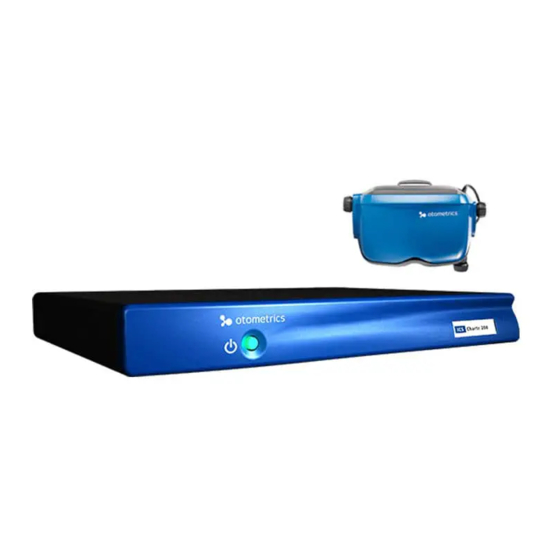
ICS Chartr 200 VNG/ENG
Installation and Startup Guide
Doc. No. 7-26-3000-EN/11
Part No. 7-26-30000-EN
Advertisement
Table of Contents

Subscribe to Our Youtube Channel
Related Manuals for natus Otometrics ICS Chartr 200 VNG/ENG


Summary of Contents for natus Otometrics ICS Chartr 200 VNG/ENG
- Page 1 ICS Chartr 200 VNG/ENG Installation and Startup Guide Doc. No. 7-26-3000-EN/11 Part No. 7-26-30000-EN...
- Page 2 Copyright notice © 2015, 2019 Natus Medical Denmark ApS. All rights reserved. ® Otometrics, the Otometrics Icon, AURICAL, MADSEN, Otoscan, ICS and HORTMANN are registered trademarks of Natus Medical Denmark ApS in the U.S.A. and/or other countries. Version release date 2019-05-15 (213483) Technical support Please contact your supplier.
-
Page 3: Table Of Contents
Table of Contents Introduction Prepare System for Data Collection Prepare Patient for Testing Collect Patient Data Review and Analyze Collected Data Print a Patient Report System Options and Settings Maintenance and Troubleshooting Safety 10 Manufacturer 11 Technical Specifications 12 Installation Otometrics - ICS Chartr 200 VNG/ENG... -
Page 5: Intended Use
1 Introduction Introduction ICS Chartr 200 VNG/ENG is indicated for videonystagmography and/or electronystagmography testing for patients with a complaint of dizziness or imbalance. ICS Chartr 200 VNG/ENG Installation and Startup Guide is intended for first time users of the system. It begins with step-by-step instructions for setting up records, preparing the patient, collecting data, reviewing and analyzing data, and preparing reports. -
Page 6: Prepare System For Data Collection
2 Prepare System for Data Collection Prepare System for Data Collection System Startup Step 1 A. Press the Power button on the PC and wait for the Windows ® Desktop to display. Patient Selection Alternate Start B. Double-click (ICS VNG or ENG icon) to display the dialog. - Page 7 2 Prepare System for Data Collection Start a New Patient Record Step 2 A. Complete the patient information. Patient Information 1. Select the tab. 2. Type the patient’s Last Name – [required] First Name – [required] Birth – information [required] Gender 3.
- Page 8 2 Prepare System for Data Collection Select a Referring Physician and Facility Step 3 A referring physician can be associated with a patient record. This association is called a Physician Order. A. Select a Referring Physician Referring Facility 1. Click the Physician’s Order Referring Physician 2.
- Page 9 2 Prepare System for Data Collection Answer Clinical Information Questions Step 4 The clinical information questions seek information about the patient’s general condition, and eye and ear examination findings. This information can be included in the patient report. A. Click the Clinical Information tab.
- Page 10 2 Prepare System for Data Collection Add an Operator Step 5 A. Select Edit > Operator Info B. Complete the operator information. 1. Click 2. Type your: Last Name – [required] First Name – [required] – Address – City State Zip Code Country –...
- Page 11 2 Prepare System for Data Collection Modify Operator Options Step 6 Each operator may establish collection, review, and report settings. These settings will be in effect each time the oper- ator’s name is selected. A. Select Edit > System Options .
- Page 12 2 Prepare System for Data Collection Modify the Test Battery Step 7 In addition to establishing collection, review, and report settings, each operator may create a customized test battery (test- ing sequence). A. Select Edit > System Options . Select the Operator Settings/Test Battery tab.
- Page 13 2 Prepare System for Data Collection Add a Referring Physician Step 8 Referring physician records are available to all operators. If the referring physician’s name is not on the list, create a new record. A. Click to start a new record and type the requested information. 1.
- Page 14 2 Prepare System for Data Collection C. Go to Step 3 Select a Referring Physician and Facility ► (item A4 Referring Notes). 2.10 Study the Main Window Step 10 The Main Window is the primary workspace. When a patient record is open, it contains patient test and analysis data. Main Window A.
-
Page 15: Prepare Patient For Testing
3 Prepare Patient for Testing Prepare Patient for Testing ENG – Apply Electrodes Step 11 The ENG system records 2 or 4 channels of eye movement information. Channel designations relate to electrode place- ment both on the face and in the electrode patient cable. A. - Page 16 3 Prepare Patient for Testing ENG – Check Electrodes Step 12 Impedance is measured at each skin-electrode interface. A question mark (?) indicates an unacceptable electrode con- nection. A. Select a protocol in the New Test tab, then click F7 Electrode Test B.
- Page 17 3 Prepare Patient for Testing VNG – Place Goggles on Patient Step 13 The video goggles contain video camera lenses and mirrors. The video image displays on the monitor. For more inform- ation about how the goggles function, refer to the User Manual. A.
-
Page 18: Collect Patient Data
4 Collect Patient Data Collect Patient Data VNG – Center and Focus the Video Image Step 14 A. Click the New Test tab on the Main Window and choose the eye(s) to be tested. F7 Video Adjust B. Click to display the Video Adjustments dialog. C. - Page 19 4 Collect Patient Data Caution Do not over tighten the knobs as this may damage the adjustment pieces that hold the mirror. • Auto Adjust E. Click the button to move the slides automatically until the pupils begin tracking. Video Adjustments Dialog Box, One Eye Go to Step 15 VNG –...
- Page 20 4 Collect Patient Data VNG – Fine Tune the Video Image Step 15 A. Use the software controls to fine tune the video image for each eye, if needed. 1. Only the pupil should be blue. There should be none or a minimal amount of blue surrounding the eye (i.e., eye- lashes).
- Page 21 4 Collect Patient Data Check the Range Step 16 A range sensor provides a continuous display of patient-to-light bar distance. The acceptable range during testing is 3 feet 8 inches to 4 feet 4 inches (111.8 cm to 132.1 cm). If a patient is “out of range” for more than 10% of a test, a message dis- plays at the end of the test.
- Page 22 4 Collect Patient Data Select a Protocol Step 17 A. Click the New Test tab on the left side of the Main Window. New Test tab (A) Procedure (B) Protocol (C) Click on a + sign to show the hidden protocols. Click on a –...
- Page 23 4 Collect Patient Data Calibrate the Patient Step 18 The horizontal channel should always be calibrated if possible. The vertical channel is more difficult for patients, and it is acceptable to use F3 Default Calibration. To perform an individual eyes calibration, select an individual eyes protocol. A.
- Page 24 4 Collect Patient Data F12 Stop Click Note The system accepts the calibration or displays this error message: • • Click to calibrate the system before running the selected test. F4 Resume Then press and repeat D through F. • Click Use Default Calibration calibrate the system using the...
- Page 25 4 Collect Patient Data Start Data Collection Step 19 The operator may start and stop data collection at any time. A test may be repeated and saved. The first test is designated as primary, the others are secondary. Primary test results will be included in the patient report (see Step 32 Print the ►...
- Page 26 4 Collect Patient Data VNG – Record Video Image Step 20 ICS Chartr 200 VNG/ENG records up to 2 minutes of eye movement video for each test and saves the recording with the patient record. A small camera icon next to a patient name in the Patient Selection dialog or protocol in the Review tab indicates the existence of a video recording.
- Page 27 4 Collect Patient Data D. Monitor video collection activity. 1. Monitor right and left eye move- ment (A). 2. Monitor remaining time (B). Restart Click button to discard any recorded video and to begin video recording. Stop Click button to stop recording video.
-
Page 28: Review And Analyze Collected Data
5 Review and Analyze Collected Data Review and Analyze Collected Data Display Collected Data Step 21 A. Click the Review tab. Physician Order B. Select a date and Session. 1. Click the and select a date. 2. Expand a session (A). 3. - Page 29 5 Review and Analyze Collected Data Reassign Primary Test Status Step 22 When a test is run more than once during a test session, the system assigns primary status to the first test run and sec- ondary status to the others. Only primary test results are included in the patient report and only the four bolded caloric tests are included in the caloric summary display and the calculations.
- Page 30 5 Review and Analyze Collected Data Reposition Waveforms Step 23 During review, you may view and manipulate collected waveforms. A. Select and move a waveform. 1. Use the scroll bar to view the entire waveform (A). 2. Click on a waveform handle (B). äã...
- Page 31 5 Review and Analyze Collected Data Review a Calibration Step 24 A. Click on a test on the Review tab. B. Press F8 Review Calib. The calibration data is saved with a test and can be reviewed. Each calibration record contains the last 10 seconds of the calibration.
- Page 32 5 Review and Analyze Collected Data Analyze Saccade Test Results Step 25 A. Click the Review tab and select a Saccade test. B. Click F12 Analysis Analysis Averaged Averaged & Raw C. Select > , or to see different views of the data. 1.
- Page 33 5 Review and Analyze Collected Data Click on a data point (A) to move the tracing (B) to correspond with the analysis result. Amplitude – eye movement (in degrees) between the initial pos- ition and the first stop. Accuracy – amplitude of a saccade divided by the amplitude of target movement;...
- Page 34 5 Review and Analyze Collected Data Analyze Sinusoidal Tracking Step 26 A. Click the Review tab and select a Tracking test. B. Click F12 Analysis Analysis Averaged Averaged & Raw C. Select > , or to see different views of the data. Click an option to select it (A).
- Page 35 5 Review and Analyze Collected Data 1. Click on a data point (A) to move the tracing (B) to correspond with the analysis result. The shaded area on the Tracking Gain chart represents normative data. Use this information to compare the aver- aged responses.
- Page 36 5 Review and Analyze Collected Data Analyze Slow Phase Velocity (SPV) Measurements Step 27 A. Click the Review tab and select a Caloric or other test to analyze nystagmus. B. Press F12 Begin to measure the slow phases and plot them on the lower chart. The number of beats analyzed displays in the Information area.
- Page 37 5 Review and Analyze Collected Data Note The vertical cursor represents the same point in time as the vertical cursor in the lower chart and exactly • bisects the slow phase of the nystagmus being measured. Vertical cursor (A). 3. Adjust the slope of the velocity measuring line to measure the slow phase of a beat:...
- Page 38 5 Review and Analyze Collected Data Caloric peak values in Information Area F12 Save E. Press to save the analysis. Go to Step 28 Analyze Caloric Test Results (Pod and Butterfly Views) ► Otometrics - ICS Chartr 200 VNG/ENG...
- Page 39 5 Review and Analyze Collected Data Analyze Caloric Test Results (Pod and Butterfly Views) Step 28 When analyzing caloric test results, the system calculates the caloric unilateral weakness and gain asymmetry. The results are shown in “Pods” and “Butterfly” views. A.
- Page 40 5 Review and Analyze Collected Data Function Keys during Pods review Help Interpret Tests Run Interpretation Assistant. SPV Graph Go to SPV Analysis view Move Baseline Up Move the green baseline up on the tracing. Move Baseline Down Move the green baseline down on the tracing Set Baseline Accept the new baseline position Close...
- Page 41 5 Review and Analyze Collected Data Interpretation Assistant Step 29 The Interpretation Assistant, a software tool provided with some systems, provides suggestions as to the validity and clin- ical significance of VNG/ENG test results. Currently, this tool works with the results from caloric and static position tests. A.
- Page 42 5 Review and Analyze Collected Data F3 Interpret Tests D. For static positions tests, click to view the analysis. Horizontal Ver- 1. Select tical Nystagmus to gen- erate results for the selected channel. Paste to Report 2. Click copy the results into the patient report.
-
Page 43: Print A Patient Report
6 Print a Patient Report Print a Patient Report Prepare the Patient Report Step 30 Patient reports consist of patient information and graphic representations of test results. The operator selects test results that will be included in the printed report and may enter his/her impression of the results in the word processor. A. - Page 44 6 Print a Patient Report Set Report Options Step 31 Each operator should plan and designate how the test results (waveforms) will appear in a printed report. The report “tem- plate” is saved with the operator information and used each time the operator prints a report. A.
- Page 45 6 Print a Patient Report C. Select the location on the page for each protocol in the report. Highlight indicates selected position (A). 1. Select a protocol. 2. Click a button. 3. Click Select – move selected protocol to high- lighted box.
- Page 46 6 Print a Patient Report Print the Report Step 32 Select the items (patient data, test results, and/or clinical information) you want to include in the printed report. Reports print on Letter or A4 size paper. A. Select File > Print Report to display the Print Report...
- Page 47 6 Print a Patient Report Print Waveforms Step 33 When reviewing or analyzing results, an individual waveform may be printed or several waveforms may be formed into a temporary report and printed. Note • This report will not be saved with the patient record. File Print Waveform File...
-
Page 48: System Options And Settings
7 System Options and Settings System Options and Settings Set Up or Edit the Test Site Facility Information Step 34 Add the test site facility information to the database. The name of the practice or clinic and the title of the report are included on the word processor report page. - Page 49 7 System Options and Settings Modify Workstation and Goggle Settings Step 35 Use this procedure to modify workstation settings or change the goggle settings. These changes are not operator specific. A. Select Edit > System Options Workstation Settings Tab. Workstation Settings B.
- Page 50 7 System Options and Settings Peak Frequency/GDT Interface Step 36 A. Select the Peak Frequency/GDT Interface Tab if you are using an International version of VNG/ENG. Peak Frequency/GDT Inter- 1. Select the face Program Language 2. Select 3. Select Peak Frequency Calculation –...
-
Page 51: Maintenance And Troubleshooting
8 Maintenance and Troubleshooting Maintenance and Troubleshooting The maintenance and troubleshooting information in this section includes: Cleaning and Maintenance • Diagnostic System Test • • Database Repair Utility A method for attempting to fix a corrupt database. Special Notice: Service and repair of electro-medical equipment should be done by the equipment manufacturer or authorized rep- resentatives. - Page 52 8 Maintenance and Troubleshooting 1. Place a drop of lens cleaning solution on a cotton swab. Avoid using excessive amounts of the solution; it can get between the lens components. 2. Wipe the surface gently with the cotton swab using a rotary motion until the surface is clean. Note Lens cleaning solution is available at camera/photography stores.
- Page 53 8 Maintenance and Troubleshooting Diagnostic System Test This diagnostic test verifies the status of system components. A. Place the electrode lead input end of the patient electrode cable into the test fixture. Plug the test fixture cable into the loopback test fixture port ( ) at the back of the ICS Chartr 200.
- Page 54 8 Maintenance and Troubleshooting ICS VNG/ENG D. Power up the computer and double-click the icon on the Windows desktop to restart the applic- ation. E. Make sure cable connections between the goggles and video goggles port on the Chartr 200 box are firmly in place. See the diagrams in the Installation Reference section.
-
Page 55: Symbols Used
9 Safety Safety This Installation and Startup Guidecontains information and warnings, which must be followed to ensure the safe per- formance of ICS Chartr 200 VNG/ENG. Local government rules and regulations, if applicable, should also be followed at all times. Symbols Used ICS Chartr 200 Symbols ICS Chartr 200 VNG/ENG is marked with this symbol to indicate compliance with Type BF of the safety... - Page 56 9 Safety Warning Notes ICS Chartr 200 VNG/ENG Warning Notes Equipment connected to the displayed connectors must be certified to relevant EN/IEC safety standards, e.g., EN/IEC 60950. Mains connected equipment – except EN/IEC 60601-1 certified equipment – must be powered from the Power- tronix Isolation Station (X1ATWFHNOC1).
- Page 57 9 Safety Note 11: Connection to network or modem components may compromise the safety or effectiveness of this system. Use fiber-optic network connections to install the computer on a network. Note 12: Installation of any third party software (applications, programs, or utilities) other than those specified by Otometrics can compromise the safety or effectiveness of this system.
-
Page 58: Manufacturer
10 Manufacturer Manufacturer Natus Medical Denmark ApS Hoerskaetten 9, 2630 Taastrup Denmark +45 45 75 55 55 www.natus.com 10.1 Responsibility of the Manufacturer The manufacturer is to be considered responsible for effects on safety, reliability, and performance of the equipment only •... -
Page 59: Technical Specifications
PC screen is usually between 40 mV and 200 mV. 11.2 ICS Chartr 200 Interface USB 2.0 or 3.0 to PC Type Identification ICS Chartr 200 is Type 1068 from Natus Medical Denmark ApS Power Supply AC/DC Adapter Type FW7362M/15 from Friwo Input... - Page 60 11 Technical Specifications Isolation Transformer Powertronix Isolation Station from Natus Medical Denmark ApS. AC/DC Adapter Input Voltage 115 (120) / 230 (240) VAC – 50/60Hz Input Current 2.7A / 1.35A Leakage Current < 100-A Output Voltage 115 (120) / 230 (240) VAC Output Current 2.6A / 1.3A...
- Page 61 11 Technical Specifications Optimal Stimulus (Including Light Bar) Patient-To-Bar Distance 4 feet (1.2 m) Ultrasonic Range Sensing Target Position Gaze Targets ± 30° Pursuit and Saccades ± 16° Computer Controlled Target Size Less than 1/2° of Arc Brightness Software Controlled Optokinetic 6 Targets Rotation...
- Page 62 11 Technical Specifications Patient Interface Distance pupil to pupil 60 ±8mm Distance eye to forehead 22 ±3mm Nose width 30 ±10mm Horizontal range of viewing angle (visor ±55° open) Vertical range of viewing angle (visor ±30° open) Calibration None Required Standards Safety: EN 60601-1, UL60601-1, CAN/CSA-C22.2 NO 601.1-M90...
- Page 63 11 Technical Specifications Cables: Cable, ICS Chartr Lightbar 7-08-10200 ICS Cable, USB type A-B, 3 meters 8-71-79100 Assy, CBL, ICS foot switch 8-35-26400 Power cord, US w/plug (UL approved) 7-08-017 Power cord. CH w/plug 7-08-027 Power cord, EU (straight) 7-08-07500 Power cord, UK (straight) 7-08-07501 Power cord, US (straight)
- Page 64 11 Technical Specifications 11.3 Guidance and manufacturer’s declaration tables • ICS Chartr 200 VNG/ENG is part of a medical electrical system and is thus subject to special safety precautions. For this reason, the installation and operating instructions provided in this document should be followed closely. •...
- Page 65 11 Technical Specifications Guidance and manufacturer's declaration - electromagnetic immunity for all equipment and systems ICS Chartr 200 VNG/ENG is intended for use in the electromagnetic environment specified below. The user of ICS Chartr 200 VNG/ENG should ensure that it is used in such an environment. Immunity test IEC 60601 Compliance level...
- Page 66 11 Technical Specifications Guidance and manufacturer's declaration - electromagnetic immunity - for equipment and systems that are NOT life-supporting ICS Chartr 200 VNG/ENG is intended for use in the electromagnetic environment specified below. The user of ICS Chartr 200 VNG/ENG should ensure that it is used in such an environment. Immunity test IEC 60601 Compliance level...
- Page 67 11 Technical Specifications Recommended separation distances between portable and mobile RF communications equipment and ICS Chartr 200 VNG/ENG The ICS Chartr 200 VNG/ENG is intended for use in an electromagnetic environment in which radiated RF disturbances are controlled. The customer or the user of the ICS Chartr 200 VNG/ENG can help prevent electromagnetic interference by maintaining a minimum distance between portable and mobile RF com- munications equipment (transmitters) and the ICS Chartr 200 VNG/ENG as recommended below, according to the maximum output power of the com- munications equipment.
-
Page 68: Installation
12 Installation Installation The Installation section provides equipment setup information for checking the cable connections for the ICS Chartr 200 VNG/ENG system. Note When ICS Chartr 200 VNG/ENG starts the first time, a Workstation name dialog box displays. Type a name •... - Page 69 12 Installation 12.2 Set Up the ICS Chartr 200 VNG/ENG Hardware The ICS Chartr 200 VNG/ENG hardware cable connections are shown on this diagram. ICS Chartr 200 VNG/ENG System Connections 1. Cable to microphone (optional) 9. Patient cable 15. Footswitch cable to remote 2.
- Page 70 12 Installation 12.3 ICS Chartr 200 Remote Control The wireless remote control consists of a transmitter and a keypad. The keypad allows the operator to remotely operate many of the VNG/ENG data collection and video recording activities without using the software function keys. Description / Function Stop video recording Start / restart video recording...
- Page 71 12 Installation Step 9Dummy number used for steps in other projects Step 10Dummy number used for steps in other projects Step 11Dummy number used for steps in other projects Step 12Dummy number used for steps in other projects Step 13Dummy number used for steps in other projects Step 14Dummy number used for steps in other projects Step 15Dummy number used for steps in other projects Step 16Dummy number used for steps in other projects...
- Page 72 12 Installation Otometrics - ICS Chartr 200 VNG/ENG...
Need help?
Do you have a question about the Otometrics ICS Chartr 200 VNG/ENG and is the answer not in the manual?
Questions and answers