Table of Contents
Advertisement
Advertisement
Table of Contents

Subscribe to Our Youtube Channel
Related Manuals for natus neoBLUE mini


Summary of Contents for natus neoBLUE mini
- Page 1 SERVICE MANUAL ® neoBLUE mini System Service Manual P/N 051466F...
- Page 2 © 2009 Natus Medical Incorporated. All rights reserved. This manual may not be reprinted or copied in whole or in part without written consent from Natus Medical Incorporated. The content of this manual may change without notice. Natus Medical Incorporated...
-
Page 3: Table Of Contents
Removing the ON/Standby Switch Removing the Light Enclosure from the Adjustable Arm Removing the Pole Mount from the Adjustable Arm About the Device Timer Spare Parts List Measuring the neoBLUE mini Light with a Radiometer ® neoBLUE mini System Service Manual P/N 051466F... -
Page 4: Product Description
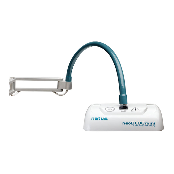
The light can be used for infants in an open bed, incubator, bassinet, or radiant warmer. 1.2 Physical Characteristics The neoBLUE mini device is a mobile phototherapy light that delivers a narrow band of high- intensity blue light via light emitting diodes (LEDs) to provide treatment for neonatal hyperbilirubinemia. - Page 5 Always protect the baby's eyes with eye patches or equivalent Authorized European Representative Manufacture Date XXXX Manufacturer Natus WEEE Directive (Waste from Electrical and Electronic Equipment Directive) Symbol – Product should not be disposed of in normal waste ® neoBLUE...
-
Page 6: Routine Maintenance Procedures
C H A P T E R 2 OUTINE AINTENANCE ROCEDURES This chapter includes procedures for routine maintenance of the neoBLUE mini device, hereafter called the UUT (Unit Under Test): Cleaning Safety Testing Performance Verification These procedures must be performed after any of the following events and/or as prescribed by the institution’s maintenance schedule. -
Page 7: Safety Testing
2.1.2 Cleaning the Interior of the Light Enclosure The cooling fan in the light enclosure will cause a buildup of dust on the components within. A Biomedical Equipment Technician should clean the inside of the light enclosure. Cleaning frequency should be determined by visual inspection of the interior. Frequency will vary depending on the environment. - Page 8 * Note: If a different radiometer is used please refer to the Conversion Chart in chapter If the meter is not listed, please contact Natus Technical Service before adjusting the LED intensity with the potentiometer. Intensity measurements are based on the patient being 12” from the panel lens of the UUT.
-
Page 9: Adjusting Light Intensity
32.5 µW/cm /nm or close to the center of the range. If step 1 complies, the UUT can be returned to service. If step 1 does not comply, refer to Chapter 3, Troubleshooting the neoBLUE mini Light. ® neoBLUE... -
Page 10: Troubleshooting The Neoblue Mini Light
C H A P T E R 3 BLUE ROUBLESHOOTING THE NEO MINI IGHT The following symptoms are discussed in this section: Light does not appear when device is turned on Lens has become excessively hot Baby becomes too warm ... - Page 11 TABLE 3.1 Troubleshooting Guide Note: neoBLUE mini device User Manual is available separately. In the USA, contact Natus Technical Service at +1 (800)-303-0306 or E-mail: technical_service@natus.com. International Support - Please contact your local Distributor. Distributor locations can be found at www.natus.com...
- Page 12 SYMPTOM PROBABLE CAUSE CORRECTIVE ACTION Verify that vents are not blocked. Air vents are If the lens surface has become hotter than blocked 50°C (122°F), verify that the fan is functioning correctly. LENS HAS BECOME EXCESSIVELY HOT If none of the above corrects the problem, open the main (ABOVE 50°C/122°F) enclosure and check for the following: Main enclosure fan...
-
Page 13: Repair Procedures
C H A P T E R 4 EPAIR ROCEDURES This section presents procedures for repairing the neoBLUE mini light, hereafter called the UUR (Unit Under Repair). Only qualified technical personnel should open the light enclosure, remove and/or replace components or make adjustments. - Page 14 FIGURE 2 The lens is removed by gently pulling it away from the light enclosure. Use caution. The lens assembly may fit tightly into light enclosure. If you are replacing the lens assembly, obtain the replacement and reverse the previous steps.
-
Page 15: Removing The Current Pcb
Removing the LED PCB The procedure in section 4.1 must be completed before beginning these steps. Remove the four Phillips head screws securing the LED PCB to the light enclosure. Locations are circled in figure 3. Timer FIGURE 3 CAUTION: Do not grasp the LEDs to remove the LED PCB from the light enclosure. The LED PCB is connected to the Current PCB by two 4-pin connectors on the upper corners of the LED PCB. -
Page 16: Removing The On/Standby Switch
Removing the Current PCB The procedures in section 4.2 must be completed before beginning these steps. Positioning guides, connectors to the LED PCB, power cable from the flexible mounting tube and cables to the ON/Standby switch hold the Current PCB. Remove the Current PCB by pulling it out of the light enclosure as shown in figure 4. -
Page 17: Removing The Light Enclosure From The Adjustable Arm
Removing the ON/Standby Switch The switch is held in the light enclosure by spring tabs, two on each side of the switch. See figure 5. Press the tabs against the switch body while pushing the switch out the top of the light enclosure. -
Page 18: Removing The Pole Mount From The Adjustable Arm
About the Device Timer The neoBLUE mini light is equipped with a timer to track the total number of hours it is switched on. The timer will count up to a maximum of 99999.9 hours. The decimal point will be flashing at a steady rate when the timer is counting. -
Page 19: Spare Parts List
Spare Parts List Item Part Description Qty. Number Adjustable Arm 040806 with Pole Mount and Power Supply Enclosure, 040821 Polycarbonate 040783 Current PCB 001839 LED PCB 800240 Nylon Washer 600122 On/Standby Switch 030745 Plate w/Insert 030748 Tab Washer 800244 Locking Nut Screw, Phillips Pan 800106 Head, 4-40 x ¼”,... - Page 20 The intensity of the light is inversely related to the distance from the source. The neoBLUE mini LED Phototherapy system can be placed closer to the infant, yielding a higher intensity and thus delivering a higher dosage treatment.
Need help?
Do you have a question about the neoBLUE mini and is the answer not in the manual?
Questions and answers