Table of Contents
Advertisement
Quick Links
Advertisement
Table of Contents

Related Manuals for natus Dantec Focus


Summary of Contents for natus Dantec Focus
- Page 1 FOCUS Hardware Instructions for Use...
- Page 2 This system is CE marked in conformity with the requirements in the Medical Device Directive 93/42/EEC. Alpine Biomed, ApS is a division of Natus Medical Incorporated. Alpine Biomed and Keypoint are registered trademarks of Alpine Biomed in the U.S. and in other countries.
-
Page 3: Table Of Contents
Focus Instructions for Use Contents Focus with Leadpoint Software ................. 4 Intended Use ......................4 Safety Information ....................4 Safety Requirements ..................... 6 Excerpt from the IEC 60601-1 (IEC 60601-1-1) Standard ......... 8 Maintenance ......................9 Decontamination ....................9 Cleaning Instructions .................... 9 Preventative Maintenance .................. -
Page 4: Focus With Leadpoint Software
Focus Instructions for Use Focus with Leadpoint Software Intended Use The Leadpoint Focus microelectrode targeting system is intended to assist in neurosurgical procedures where recording of neuronal activity and stimulation of brain neurons will aid in the placement of depth electrodes. The Leadpoint Focus microelectrode targeting system is intended to be used in the operating room by a neurosurgeon, neurologist, or clinical neurophysiologist. - Page 5 Focus Instructions for Use Simultaneous connection of a patient to HF surgical equipment may result in burns at the site of the electrical stimulation or recording electrodes, and possible damage to the electrical stimulator or the electrode input amplifiers. Operation in close proximity (e.g.
-
Page 6: Safety Requirements
Focus Instructions for Use Electrostatic Sensitive Amplifier Input connectors – Do not touch the Amplifier Input connectors as it may damage the amplifier, or affect its performance. Cautions Always use shielded power line cables from Alpine Biomed to avoid hum line interference, especially near the patient, or the amplifier. - Page 7 Focus Instructions for Use WARNING Any interruption of the protective earth conductor inside or outside of the device or disconnection of the protective/functional earth connector is likely to make the device dangerous. Intentional interruption is prohibited. The protective earth / ground conductor should be checked regularly.
-
Page 8: Excerpt From The Iec 60601-1 (Iec 60601-1-1) Standard
Focus Instructions for Use Excerpt from the IEC 60601-1 (IEC 60601-1-1) Standard WARNING When connecting other equipment, qualified attention must be paid to the following excerpt from the medical safety standard to which this system complies. IEC 60601-1-1 Medical Electrical Equipment, Part 1: General Requirements for Safety. -
Page 9: Maintenance
Focus Instructions for Use Maintenance Decontamination Decontamination that can be performed by the operator is limited to cleaning and disinfecting the device. Any maintenance inside the device must be performed by qualified service personnel only. Cleaning Instructions Regular cleaning maintenance should be performed according to frequency of use of the device. -
Page 10: Waste Management
Focus Instructions for Use Waste Management WEEE - Waste Electrical and Electronic Equipment Compliance Do not dispose of this product in the unsorted municipal waste stream. Dispose of this product according to the local regulations. – 10 –... -
Page 11: Classification
Focus Instructions for Use Classification Type of protection against electric shock: class I: Equipment in which protection against electric shock does not rely on basic insulation only, but which includes an additional safety precaution in that means are provided for the connection of the equipment to the protective earth conductor in the fixed wiring of the installation in such a way that accessible metal parts cannot become live in the event of a failure of the basic insulation. -
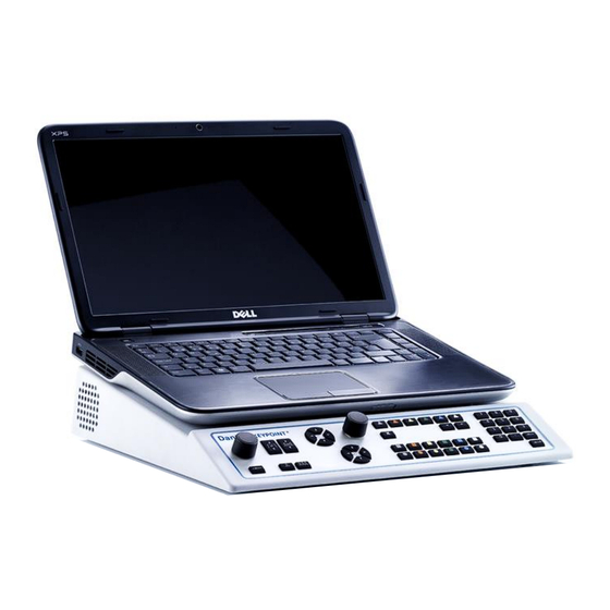
Page 12: System Overview
Focus Instructions for Use System Overview Focus Main Unit (1) Main Unit (2) Notebook PC (3) Rear Panel (4) Side Panel (5) Control Panel – 12 –... -
Page 13: System Setups
Focus Instructions for Use System Setups Focus Notebook Configuration Focus Standard PC Configuration – 13 –... - Page 14 Focus Instructions for Use Cable Connections Before operating the device, the system parts need to be connected. Follow the steps 1-3 below. 1. Connect all the signal interface cables (USB / HS-Link) as depicted in the illustrations. 2. Connect all the power interface cables as depicted in the illustrations, except the power cord.
-
Page 15: Main Unit
Focus Instructions for Use Main Unit Connection ― Side Panel 9033G0704: 9033G0701: 9033G0703: LINK CC Stimulator Output (isolated) The CC stimulator output connectors are electronically isolated. CC Stimulator Output Socket (isolated) Support for the Macro Stimulator. LINK HS Link Output Connector - MER Amplifier Connection AEP Headset Connector VEP Goggles Connector –... - Page 16 Focus Instructions for Use Rear Panel 9033G0704: Input: 100-240Vac, 50/60Hz, Max. 300VA F1, F2: T4A/250V Output: Mains, Max. 200VA LINK 9033G0701: 9033G0703: Input: 100-240Vac, 50/60Hz, Max. 300VA F1, F2: T4A/250V Output: Mains, Max. 200VA LINK HS Link Output Connector - MER Amplifier Connection Protective Earth Functional Earth To be used for suppression of noise.
-
Page 17: Technical Specifications
Focus Instructions for Use Input / Output Connector Input / Output Magnetic Stimulation/tendon hammer, or synchronization of external trigger, or external stimulation acquisition. VEP Monitor Connector Power Outlet (only for Notebook PC when not used with the Isolating Transformer) Output: Mains 100 - 240VA Max.200VA Power Inlet Input: 100-240Vac, 50/60Hz, Max. -
Page 18: Control Panel
Focus Instructions for Use Control Panel (1) Stimulation Intensity Control Knob (2) Stimulation Duration Arrow Keys (3) Stimulation Repetition Rate Arrow (4) Trace/Marker and Trigger Arrow Keys Keys (5) Cursor Mode Indicator (6) Volume/Cursor Control Knob (7) Volume Indicator (8) Loudspeaker Mute Indicator (9) Loudspeaker Mute Key (10) Software Navigation Keys (11) Numeric Keypad... -
Page 19: Control Functions
Focus Instructions for Use Control Functions Power On / Stand By Indicators Power On Stand By Software Navigation / Software Functions Software Navigation Keys – Color Coded The Software Navigation keys allow you to navigate through the application tabs. The 6 Software Navigation keys’ colors and functions correspond to those of the Software Navigation buttons on the application. - Page 20 Focus Instructions for Use Stimulation Stimulation Indicator The Stimulation indicator yellow light (LED) blinks once for Single Stimulation, and intermittently for Repetitive Stimulation. Single Stimulation Key When the Single Stimulation key is pressed, a single stimulus is released, and the indicator blinks once. The Single Stimulation key can also be used to stop Repetitive Stimulation.
- Page 21 Focus Instructions for Use Stimulation Duration Arrow Keys The Stimulation Duration Up and Down arrow keys allow you to increase / decrease the duration of the stimulation. The Up arrow key Increases the stimulation duration. The Down arrow key decreases the stimulation duration. Stimulation Repetition Rate Arrow Keys The Stimulation Repetition Rate Up and Down arrow keys increase and decrease the stimulation repetition rate.
- Page 22 Focus Instructions for Use Cursor Mode Indicator The green light (LED) indicator is on when the cursor mode is enabled. When enabled, it allows you to move the Trace / Marker or the trigger cursor with the use of the control knob –see the control knob function above.
-
Page 23: Amplifier
Focus Instructions for Use Amplifier MER Amplifier ― 5 Channels Amplifier Input (isolated) All amplifier input connectors are electronically isolated. Electrostatic Sensitive Amplifier Input Connectors WARNING Do not touch the Amplifier Input connectors as it may damage the amplifier, or affect its performance. - Page 24 Focus Instructions for Use 5 Channel Input Connector (Multi-Channel Connector) The amplifier channel (1-5) input connector features each a pair of 1.5 mm touch-proof connectors. –See Warning above for the Electrostatic Sensitive Amplifier Input Connectors. Active Electrode - Black The Active electrode corresponds to the black input connector.
-
Page 25: Stimulator
Focus Instructions for Use Stimulator Safety Information Warnings When operating the current stimulators be careful not to expose patients to high currents. Before connecting or disconnecting the stimulation electrode, always “reset” the stimulator. Simultaneous connection of a patient to HF surgical equipment may result in burns at the site of the electrical stimulation, or recording electrodes and possible damage to the electrical stimulator, or the electrode input amplifiers. - Page 26 Focus Instructions for Use Note that stimulator overload occurs when the current output of the stimulator does not match the specified current. Stimulator overload may be caused due to: One or more microelectrode cable connectors have fallen off. Too high microelectrode impedance. ...
-
Page 27: Macro Stimulator
Focus Instructions for Use Macro Stimulator NOTES Before starting stimulation, you need to manually disconnected the Micro Electrode Cable from the MER Amplifier and connect it to the Macro Stimulator device. The Macro Stimulator device allows you to select the active output channel and 5x pre-defined stimulation intensities. - Page 28 Focus Instructions for Use Channel Selection (1-5) / Indicator Select channel to enable stimulation. (Only active when the Multi-Cable Connector is used.) Selection of Pre-Set Stimulation Intensity /Indicator Select stimulation intensity for the selected channel. Start / Stop Repetitive Stimulation Single Channel Cable Connector / Indicator The LED indicator light is lit when the device is ready to deliver stimulation.
-
Page 29: Power Up Test
Focus Instructions for Use Power Up Test Messages While running the Leadpoint application Power Up test, the following hardware /equipment related messages may appear on the screen: Current Stimulator may be malfunctioning Problem occurred during the power up test of the stimulator. Exit the Leadpoint program and verify the cable connection. -
Page 30: Pc Requirements
Focus Instructions for Use PC Requirements Safety If the PC used is powered by the Focus module and is NOT purchased from Alpine Biomed ApS, then the following must be observed and fulfilled: • The Focus module fulfills the IEC 60601-1 [Medical Electrical equipment Part 1: General requirements for safety], and the IEC 60601-1-2 [Medical electrical equipment - Part 1-2: General requirements for basic safety and essential performance - Collateral standard: Electromagnetic compatibility - Requirements... -
Page 31: General Regulatory Symbols
Focus Instructions for Use General Regulatory Symbols The following regulatory symbols appear on the various components of the Focus system. For symbols related to the computer, monitor, and printer, refer to their accompanying documentation. For US audiences only. US Federal law restricts this device to sale by, or on the order of the physician. - Page 32 Dantec Focus Instructions for Use Please consult your local distributor for sales and support service. Natus Medical Incorporated www.natus.com Alpine Biomed ApS Tonsbakken 16-18 DK-2740 Skovlunde Denmark 9033M0311EN rev.A1...
Need help?
Do you have a question about the Dantec Focus and is the answer not in the manual?
Questions and answers