Table of Contents
Advertisement
Advertisement
Table of Contents

Related Manuals for natus Dantec Keypoint G4


Summary of Contents for natus Dantec Keypoint G4
- Page 1 Dantec Keypoint ® ® Hardware Instructions for Use 9031M1506 Rev. B - EN...
- Page 2 Dantec Keypoint G4 Blank page.
- Page 3 Hardware Instructions for Use © 2018 Natus. All rights reserved. The contents of this manual are the property of Natus. Any reproduction in whole or in part is strictly prohibited. At the time of printing / transfer to the DVD, this manual correctly described the device and its functions.
- Page 4 Dantec Keypoint G4 Blank page.
-
Page 5: Table Of Contents
Hardware Instructions for Use Table of Contents Safety Information ..........................7 Intended Use ............................ 7 Contraindications ..........................7 Side Effects............................9 Safety Requirements ........................10 Excerpt from the IEC 60601-1 Standard ..................12 System Overview ..........................13 Workstation ..........................13 Cable Connection Overview ...................... - Page 6 Dantec Keypoint G4 Blank page.
-
Page 7: Safety Information
Hardware Instructions for Use Safety Information The system is intended to be used in electrophysiological tests such as: Electromyography (EMG), Nerve Conduction Studies (NCS) and Evoked Potential (EP) recordings. For safety information related to the patient or the use of the Keypoint.NET application software, refer to the Software Instructions for Use. - Page 8 IEC 60601-1 international safety standards for medical electrical equipment. The use of accessories, electrodes, and cables other than those specified by Natus may result in increased emissions, or decreased immunity of the equipment. Do not use additional multiple socket-outlets or extension cords.
-
Page 9: Side Effects
Stimulator Overload in the software user guide, and the section Stimulators in this hardware manual for further information. Cautions Always use shielded power line cables from Natus to avoid hum line interference, especially near the patient, or the amplifier. Portable and mobile RF communication equipment can affect electrical equipment for medical use. -
Page 10: Safety Requirements
Dantec Keypoint G4 Safety Requirements CAUTION This device is intended to be used by qualified medical personnel, knowledgeable in the field of neurophysiology and neurophysiological assessment, as well as in the use of the product / Keypoint equipment. This device has been designed and tested in accordance with IEC Publication 60601-1 Medical Electrical Equipment, cf. - Page 11 The device must be disconnected from all voltage sources before being opened for any adjustment, replacement, maintenance or repair. Service must be referred to Natus authorized service personnel, except for such works described in this manual as being performed by the operator.
-
Page 12: Excerpt From The Iec 60601-1 Standard
Dantec Keypoint G4 Excerpt from the IEC 60601-1 Standard CAUTION When connecting other equipment, qualified attention must be paid to the following excerpt from the medical safety standard to which this system complies. IEC 60601-1 Medical Electrical Equipment, Part 1: General Requirements for Basic Safety and Essential Performance. -
Page 13: System Overview
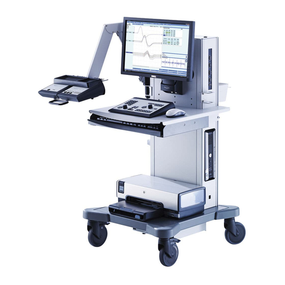
Hardware Instructions for Use System Overview Workstation (1) Computer (2) Power Switch (3) Monitor (4) Internal Speaker (5) Control Panel (6) PC Keyboard (7) Electrode Arm (optional) (8) Current Stimulator (optional) (9) Amplifier Box (optional) (10) Connection Panel (11) Accessory Box Kit (optional) (12) Mouse (13) Printer (optional) (14) LAN Socket (optional) -
Page 14: Cable Connection Overview
Dantec Keypoint G4 Cable Connection Overview A Power Supply / Isolating F Screen K Loudspeaker Transformer L Network Isolator B Printer (optional) G Amplifier Box (optional) (optional) C Computer H Stimulator Box (optional) M Cart Enclosure N DC power supply unit... -
Page 15: Cable Connections
CAUTION Use only optional devices specified by Natus in order to comply with IEC 60601-1. CAUTION Always use shielded power line cables from Natus to avoid hum line interference, especially near the patient, or the amplifier. -
Page 16: Connection Panel
Dantec Keypoint G4 Connection Panel Input / Output Connector Input / Output Magnetic Stimulation / tendon hammer, or synchronization of external trigger, or external stimulation acquisition. Footswitch Connector Pattern Stimulator Connector Auditory Stimulation Headset Connector Visual Goggles Stimulator Output Connector... -
Page 17: Power Supply / Isolating Transformer Units
Hardware Instructions for Use Power Supply / Isolating Transformer Units For detailed instructions, refer to the Power Supply or Isolating Transformer manual accompanying the units. WARNING Do not use additional multiple socket-outlets or extension cords. CAUTION Use only the 6-outlets safety power supply / isolating transformer unit for all devices of the complete system in order to comply with the IEC 60601-1. -
Page 18: Controls
Dantec Keypoint G4 Controls Control Panel (1) Standby Indicator (2) Power ON Indicator (3) Numeric Keypad (4) Software Navigation Keys (5) Sweep Speed/Sensitivity Level Arrow Keys (6) Stimulation Intensity Control Knob (7) Reset Stimulation Intensity key (8) Stimulation Duration Arrow Keys... -
Page 19: Control Functions
Hardware Instructions for Use Control Functions Software Navigation / Software Functions Software Navigation Keys – Color Coded The Software Navigation keys allow you to navigate through the application tabs. The 6 Software Navigation keys’ colors and functions correspond to those of the Software Navigation buttons on the application The Left and Right arrow keys and the Enter key allow you to select tests. -
Page 20: Stimulus Intensity / Duration / Repetition Rate
Dantec Keypoint G4 Single Stimulation Key When the Single Stimulation key is pressed, a single stimulus is released, and the indicator blinks once. The Single Stimulation key can also be used to stop Repetitive Stimulation. Repetitive Stimulation Key When the Repetitive Stimulation key is pressed, repetitive stimulus is released and the indicator blinks intermittently. -
Page 21: Loudspeaker / Volume / Cursor Mode / Trace / Marker / Trigger
Hardware Instructions for Use Loudspeaker / Volume / Cursor Mode / Trace / Marker / Trigger Loudspeaker Mute Key / Indicator Press the Loudspeaker Mute key to switch between the On and Off function. The yellow light (LED) indicates the loudspeaker is muted. To adjust the volume, see the Control knob function below. -
Page 22: Footswitch (Optional)
Dantec Keypoint G4 Footswitch (optional) Footswitches are available as a triple pedal model (A, B and C features), or as a mono pedal model (B feature). –See also Advanced Stimulation Handgrip section in this manual. Footswitch - Model with 3 Pedals... -
Page 23: Amplifiers
Hardware Instructions for Use Amplifiers Amplifier Modules: 3, 4, 6, and 8 Channels 3 Channels 4 Channels 6 Channels 8 Channels Power ON Indicator The green light (LED) indicates that the amplifier power is On. Amplifier Input (isolated) All amplifier input connectors are electronically isolated. Electrostatic Sensitive Amplifier Input Connectors WARNING Do not touch the Amplifier Input connectors as it may damage the amplifier, or affect its performance. - Page 24 Dantec Keypoint G4 Loudspeaker Mute Key / Indicator Press the Loudspeaker key to switch between the On and Off function. The yellow light (LED) indicates that the loudspeaker is muted. Active Electrode Indicator - Black The Active electrode corresponds to the black input connector.
-
Page 25: Rear Panel
Hardware Instructions for Use Rear Panel HS Link Input Connector - Connection Panel (internal) LINK HS Link Output Connector - Current Stimulator Connection LINK HS Linkport HS Linkport allows an extra module connection (e.g. stimulator). To open the HS Linkport lid, use a tool (e.g. small screwdriver). -
Page 26: Ep Amplifier Module - 6 Channels
Dantec Keypoint G4 EP Amplifier Module ― 6 Channels Power ON Indicator The green light (LED) indicates that the amplifier power is On. Amplifier Input (isolated) All amplifier input connectors are electronically isolated Electrostatic Sensitive Amplifier Input Connectors WARNING Do not touch the Amplifier Input connectors as it may damage the amplifier, or affect its performance. - Page 27 Hardware Instructions for Use Amplifier Input Connectors – Common Array The green light (LED) indicates the results of the impedance test as described below. LED Status Result All LEDs Off Acceptable Impedance Constantly lit LEDs High Impedance Amplifier Input Connectors – Head Array (Montage) The head array electrode connectors are labeled according to the International 10-20 System of Electrode Placement.
-
Page 28: Stimulators
Dantec Keypoint G4 Stimulators Safety Information Stimulators WARNING When operating the current stimulators be careful not to expose patients to high currents. Before connecting or disconnecting the stimulation electrode, always “reset” the stimulator. WARNING Simultaneous connection of a patient to HF surgical equipment may result in burns at the site of the electrical stimulation, or recording electrodes and possible damage to the electrical stimulator, or the electrode input amplifiers. -
Page 29: Advanced Stimulation Handgrip (Optional)
Hardware Instructions for Use Advanced Stimulation Handgrip (optional) (1) Output Electrode Pins For direct stimulation on the skin, see the description of the stimulation electrodes in this section. (2) Polarity and Stimulation Indicators The stimulation cathode is indicated by a constant green light (LED). During stimulation, the other LED indicator will flash yellow –once for single stimulation and intermittently for repetitive stimulation. - Page 30 Dantec Keypoint G4 (6) Button C: Start/Stop Averager – Active in Sensory Nerve testing Shortly press the button on the handle. (7) Polarity Button Press the button to change Polarity. Note on Buttons A (5) and C (6). Button A (5) has the same function as: The footswitch, pedal A;...
-
Page 31: Constant Current Stimulators
Hardware Instructions for Use Constant Current Stimulators Single CC Stimulator Multi CC Stimulator - - Power ON Indicator The green light (LED) indicates that the stimulator power is On. CC Stimulator Output (isolated) CC stimulator output connectors are electronically isolated. Stimulus Release Indicator Flashes for the stimulation pulse. -
Page 32: Additional Information Related To Stimulation
Dantec Keypoint G4 Additional information related to stimulation Source Voltage The source voltage for the current stimulators is approx. 400 V. If the load impedance exceeds 400 V/I , where I denotes the selected stimulating current, the stimulators skin skin will be unable to provide the selected currents. - Page 33 Hardware Instructions for Use Maximum Current Density Attention! If the current density exceeds 2 mA rms/cm , it may require the special attention of the user (the risk of burning the skin). The max. pulse current will depend on the frequency of the stimulation, pulse width and the area of the electrode.
-
Page 34: Power Up Test
Dantec Keypoint G4 Power Up Test Warnings While running the Keypoint.NET application Power Up test, the following hardware /equipment related warnings may appear on the screen: Current Stimulator may be malfunctioning: Problem occurred during the power up test of the stimulator. Exit the Keypoint.NET program, and verify the cable connection. -
Page 35: Maintenance
Hardware Instructions for Use Maintenance Cleaning Instructions The maintenance that can be performed by the operator is limited to the device. Any maintenance inside the device must be performed by qualified service personnel only. The cleaning procedure must be in accordance with your local hygiene authority’s guidelines for cleaning. -
Page 36: Classification
Dantec Keypoint G4 Classification Type of protection against electric shock: class I: Equipment in which protection against electric shock does not rely on basic insulation only, but which includes an additional safety precaution in that means are provided for the... -
Page 37: General Regulatory Symbols
Hardware Instructions for Use General Regulatory Symbols Rx only For US audiences only. US laws restrict this device to sale by, or on the order of the physician. The devices comply with the EC directive 93/42/EEC with amendments up to 2007/47/EEC for Medical devices. Consult Instructions for Use. -
Page 38: Electromagnetic Compatibility
Dantec Keypoint G4 Electromagnetic compatibility Requirement Description The system is intended to be used in Hospitals and Private practice clinic except for near Environment for active HF surgical equipment and RF shielded room of system for magnetic resonance imaging, where the intensity of electromagnetic disturbances is high. -
Page 39: List Of System Items, Additional And Optional Parts
Hardware Instructions for Use List of system items, additional and optional parts List of all modules, cables and accessories with which the manufacturer of the Keypoint G4 claims compliance. The customer or the user of the Keypoint G4 should assure that it is used with these parts. Type Guidance 9031G0711... - Page 40 Dantec Keypoint G4 9031E017- Advanced stim handgrip Cable length 2.5 m 9031E027- Tubal ear inserts Cable length 5 m 9031E025- Headset Cable length 5 m 9031E026- Screened headset Cable length 5 m 9031E028- Bone conductor Cable length 5 m 9031B030- Footswitch, 3 key Cable length 2.5 m...
- Page 41 Hardware Instructions for Use Please consult www.natus.com for your local Sales & Service office. Natus Manufacturing Limited IDA Business Park Gort, Co. Galway, Ireland Rx only Reg. No. 9031M1506 Rev B – EN...
- Page 42 Dantec Keypoint G4...
Need help?
Do you have a question about the Dantec Keypoint G4 and is the answer not in the manual?
Questions and answers