Table of Contents
Advertisement
Advertisement
Table of Contents

Related Manuals for natus Dantec Keypoint Focus


Summary of Contents for natus Dantec Keypoint Focus
- Page 1 Dantec Keypoint Focus ® ® Hardware Instructions for Use 9033M3703EN Rev. C...
- Page 2 Hardware Instructions for Use Blank page...
- Page 3 Dantec Keypoint Focus Copyright © 2019 Natus. All rights reserved. The contents of this manual are the property of Natus. Any reproduction in whole or in part is strictly prohibited. At the time of printing / transfer to the DVD, this manual correctly described the device and its functions.
- Page 4 Hardware Instructions for Use Blank page...
-
Page 5: Table Of Contents
Dantec Keypoint Focus Table of Contents Intended Use ............................7 Safety Information ..........................7 Contraindications ..........................7 Danger ............................... 7 Warnings ............................8 Cautions ............................. 9 Side Effects ............................. 9 Safety Requirements ..........................10 Excerpt from the IEC 60601-1 Standard ....................12 System Overview .......................... - Page 6 Hardware Instructions for Use PC Requirements ..........................37 Safety ..............................37 Performance ............................37 Maintenance ............................38 Cleaning Instructions ..........................38 Safety Checks............................38 Waste Management ........................... 39 Classification ............................39 General Regulatory Symbols ......................40 Electromagnetic compatibility ......................41 List of system items, additional and optional parts ................
-
Page 7: Intended Use
Dantec Keypoint Focus Intended Use Keypoint Focus is intended as an electrophysiological aid to assess diagnosis and prognosis, and to monitor diseases of the central and peripheral nervous system. It can also be used to study functional aspects of nerves and muscles in other fields such as rehabilitation (physical medicine), occupational medicine and sports medicine. -
Page 8: Warnings
Do not use this PC-based equipment for anything else other than what it is intended for by the manufacturer −i.e. carrying out tests on patients and possibly subsequent report generation. Do not install any other software than the Keypoint.NET Software. Natus assumes no responsibility when the equipment is not used as described in this manual. -
Page 9: Cautions
Dantec Keypoint Focus The use of accessories, electrodes, and cables other than those specified by Natus may result in increased emissions, or decreased immunity of the equipment. Use only optional devices specified by Natus in order to comply with IEC 60601-1. -
Page 10: Safety Requirements
Hardware Instructions for Use Safety Requirements CAUTION This device is intended to be used by qualified medical personnel, knowledgeable in the field of neurophysiology and neurophysiological assessment, as well as in the use of the product / Keypoint equipment. This device has been designed and tested in accordance with IEC 60601-1 Medical Electrical Equipment, cf. - Page 11 The device must be disconnected from all voltage sources before being opened for any adjustment, replacement, maintenance or repair. Service must be referred to Natus authorized service personnel, except for such works described in this manual as being performed by the operator.
-
Page 12: Excerpt From The Iec 60601-1 Standard
Hardware Instructions for Use Excerpt from the IEC 60601-1 Standard CAUTION When connecting other equipment, qualified attention must be paid to the following excerpt from the medical safety standard to which this system complies. IEC 60601-1 Medical Electrical Equipment, Part 1: General Requirements for Basic Safety and Essential Performance. -
Page 13: System Overview
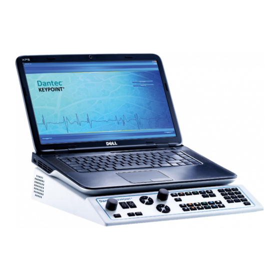
Dantec Keypoint Focus System Overview Keypoint Focus Main Unit Main Unit (Notebook PC Rear Panel Side Panel Control Panel... -
Page 14: System Setups
Hardware Instructions for Use System Setups KEYPOINT Notebook PC KEYPOINT Standard... -
Page 15: Cable Connections
3. Connect the power cord to the wall outlet. CAUTION Use only optional devices specified by Natus in order to comply with IEC 60601- CAUTION Always use shielded power line cables from Natus to avoid hum line interference, especially near the patient, or the amplifier. -
Page 16: Rear Panel
Hardware Instructions for Use CC Stimulator Output (isolated) The CC stimulator output connectors are electronically isolated. CC Stimulator Output Socket (isolated) For connection of stimulation electrodes with DIN plugs. Support for the active handgrip. HS Link Output Connector - Amplifier Connection LINK AEP Headset Connector VEP Goggles Connector... -
Page 17: Technical Specifications
Dantec Keypoint Focus Dual USB Connectors – Type A Limited power available. Only used for memory stick and license dongle. USB Connector – Type B For computer interface. Footswitch Connector Input / Output Connector Input / Output Magnetic Stimulation /tendon hammer, or synchronization of external trigger, or external stimulation acquisition. -
Page 18: Controls
Hardware Instructions for Use Controls Control Panel (1) Stimulation Intensity Control Knob (2) Stimulation Duration Arrow Keys (3) Stimulation Repetition Rate Arrow Keys (4) Trace/Marker and Trigger Arrow Keys (5) Cursor Mode Indicator (6) Volume/Cursor Control Knob (7) Volume Indicator (8) Loudspeaker Mute Indicator (10) Software Navigation Keys (9) Loudspeaker Mute Key... -
Page 19: Control Functions
Dantec Keypoint Focus Control Functions Power On / Stand By Indicators Power On Stand By Software Navigation / Software Functions Software Navigation Keys – Color Coded The Software Navigation keys allow you to navigate through the application tabs. The 6 Software Navigation keys’ colors and functions correspond to those of the Software Navigation buttons on the application. - Page 20 Hardware Instructions for Use Stimulation Indicator The Stimulation indicator yellow light (LED) blinks once for Single Stimulation, and intermittently for Repetitive Stimulation. Single Stimulation Key When the Single Stimulation key is pressed, a single stimulus is released, and the indicator blinks once. The Single Stimulation key can also be used to stop Repetitive Stimulation.
- Page 21 Dantec Keypoint Focus Stimulation Duration Arrow Keys The Stimulation Duration Up and Down arrow keys allow you to increase / decrease the duration of the stimulation. The Up arrow key Increases the stimulation duration. The Down arrow key decreases the stimulation duration.
-
Page 22: Footswitch (Optional)
Hardware Instructions for Use Cursor Mode Indicator The green light (LED) indicator is on when the cursor mode is enabled. When enabled, it allows you to move the Trace / Marker or the trigger cursor with the use of the control knob –see the control knob function above. -
Page 23: Amplifiers
Dantec Keypoint Focus Amplifiers Amplifier Module ― 3 Channels Amplifier Input (isolated) All amplifier input connectors are electronically isolated. Electrostatic Sensitive Amplifier Input Connectors WARNING Do not touch the Amplifier Input connectors as it may damage the amplifier, or affect its performance. - Page 24 Hardware Instructions for Use Patient Ground Connectors Connect the patient's ground electrodes to the green connectors. WARNING Do not connect the "patient ground" to the protective earth connection on the Isolating Transformer Unit, or to any other "ground" connections, as the electrode inputs are galvanically isolated.
-
Page 25: Amplifier Modules - 3, 4, 6, 8 Channels
Dantec Keypoint Focus Amplifier Modules ― 3, 4, 6, 8 Channels 3 Channels 4 Channels 6 Channels 8 Channels Power ON Indicator The green light (LED) indicates that the amplifier power is Amplifier Input (isolated) All amplifier input connectors are electronically isolated. - Page 26 Hardware Instructions for Use Reference Electrode Indicator - Red The Reference electrode corresponds to the red input connector. The green light (LED) indicates the results of the impedance test. –See the LED Status and Results description under the Active Electrode Indicator above. Amplifier Input Connectors (1-3) or (1-4) The amplifier input connectors 1-3 feature both a DIN-type socket and a pair of 1.5 mm touch-proof connectors.
- Page 27 Dantec Keypoint Focus Rear Panel HS Link Input Connector - Main Unit – Side Panel LINK WARNING Due to risk of electric shock, the operator and / or patient must not directly or indirectly touch the metal shield on the LINK cable attached to the rear of the amplifier.
-
Page 28: Ep Amplifier Module - 6 Channels
Hardware Instructions for Use EP Amplifier Module ― 6 Channels Power ON Indicator The green light (LED) indicates that the amplifier power is On. Amplifier Input (isolated) All amplifier input connectors are electronically isolated Electrostatic Sensitive Amplifier Input Connectors WARNING Do not touch the Amplifier Input connectors as it may damage the amplifier, or affect its performance. - Page 29 Dantec Keypoint Focus Amplifier Input Connectors – Common Array The green light (LED) indicates the results of the impedance test as described below. LED Status Result All LEDs Off Acceptable Impedance Constantly lit LEDs High Impedance Amplifier Input Connectors – Head Array (Montage)
-
Page 30: Current Stimulators
Hardware Instructions for Use Current Stimulators Safety Information Stimulator WARNING When operating the current stimulators, be careful not to expose patients to high currents. Before connecting or disconnecting the stimulation electrode, always “reset” the stimulator. WARNING Simultaneous connection of a patient to HF surgical equipment may result in burns at the site of the electrical stimulation, or recording electrodes and possible damage to the electrical stimulator, or the electrode input amplifiers. -
Page 31: Advanced Stimulation Handgrip (Optional)
Dantec Keypoint Focus Advanced Stimulation Handgrip (optional) (1) Output Electrode Pins For direct stimulation on the skin, see the description of the stimulation electrodes in this section. (2) Polarity and Stimulation Indicators The stimulation cathode is indicated by a constant green light (LED). During stimulation, the other LED indicator will flash yellow –once for single stimulation and intermittently for... - Page 32 Hardware Instructions for Use Shortly press the button on the handle. (5) Button A: Next Test – Active in Motor, Sensory, F wave and H Reflex Press and hold down the button on the handle for at least 2 seconds. (6) Button C: Start/Stop Averager –...
-
Page 33: Multi-Constant Current Stimulator Module
Dantec Keypoint Focus Multi-Constant Current Stimulator Module Power ON Indicator The green light (LED) indicates that the stimulator power is On. CC Stimulator Output (isolated) CC stimulator output connectors are electronically isolated. Stimulus Release Indicator Flashes for the stimulation pulse. -
Page 34: Additional Information Related To Stimulation
Hardware Instructions for Use Additional information related to stimulation Source Voltage The source voltage for the current stimulators is approx. 400 V. If the load impedance exceeds 400 V/I , where I denotes the selected stimulating current, the stimulators will be unable to skin skin provide the selected currents. -
Page 35: Maximum Current Density
Dantec Keypoint Focus Maximum Current Density Attention! If the current density exceeds 2 mA rms/cm , it may require the special attention of the user (the risk of burning the skin). The max. pulse current will depend on the frequency of the stimulation, pulse width and the area of the electrode. -
Page 36: Power Up Test
Hardware Instructions for Use Power Up Test Warnings While running the Keypoint.NET application Power Up test, the following hardware /equipment related warnings may appear on the screen: Current Stimulator may be malfunctioning: Problem occurred during the power up test of the stimulator. Exit the Keypoint.NET program, and verify the cable connection. -
Page 37: Pc Requirements
PC Requirements Safety If the PC used is powered by the Keypoint Focus module and is NOT purchased from Natus, then the following must be observed and fulfilled: • The Keypoint Focus module fulfills the IEC 60601-1 [Medical Electrical equipment Part 1:... -
Page 38: Maintenance
Hardware Instructions for Use Maintenance Cleaning Instructions The maintenance that can be performed by the operator is limited to cleaning the device. Any maintenance inside the device must be performed by qualified service personnel only. Regular cleaning maintenance should be performed according to frequency of use of the device. -
Page 39: Waste Management
Dantec Keypoint Focus Waste Management Waste Electrical and Electronic Equipment: Compliance Information. Do not dispose of this product in the unsorted municipal waste stream. Dispose of this product according to the local regulations. Classification Type of protection against electric shock: class I: ... -
Page 40: General Regulatory Symbols
Hardware Instructions for Use General Regulatory Symbols The devices comply with the EC directive 93/42/EEC with amendments up to 2007/47/EEC for Medical devices. Instructions for Use. Follow instructions for use. Warnings associated with this device. / Attention! Read instructions for use. -
Page 41: Electromagnetic Compatibility
Dantec Keypoint Focus Electromagnetic compatibility Requirement Description The system is intended to be used in Hospitals and Private practice clinic except for near Environment for active HF surgical equipment and RF shielded room of system for magnetic resonance imaging, where the intensity of electromagnetic disturbances is high. -
Page 42: List Of System Items, Additional And Optional Parts
The customer or the user of the Keypoint Focus should assure that it is used with these parts. Type Guidance 9033G070- * Focus Main Unit 9033C073- Natus 3-ch. EMG/EP Amplifier 9033C074- 4-ch. EMG/EP Amplifier 9033C076- 6-ch. EMG/EP Amplifier 9033C077- 6-ch. EP Amplifier 9033C078- 8-ch. - Page 43 Dantec Keypoint Focus 9031D040- Isolating transformer 115V 9031D041- Isolating transformer 230V 9031E017- Advanced stim handgrip Cable length 2.5 m 9031E027- Tubal ear inserts Cable length 5 m 9031E025- Headset Cable length 5 m 9031E026- Screened headset Cable length 5 m...
- Page 44 Hardware Instructions for Use Please consult www.natus.com for your local Sales & Service office. Natus Manufacturing Limited IDA Business Park Gort, Co. Galway, Ireland RX only Reg. No. 9033M3703EN Rev C...
Need help?
Do you have a question about the Dantec Keypoint Focus and is the answer not in the manual?
Questions and answers