Table of Contents
Advertisement
Quick Links
Advertisement
Table of Contents

Related Manuals for Flavel FRLCP0MN


Summary of Contents for Flavel FRLCP0MN
- Page 1 Installation and Maintenance Instructions Hand these instructions to the user Model No’s FRLCP0MN & FRLCN0MN are for use on Natural Gas (G20) at a supply pressure of 20 mbar in G.B. / I.E. Supplied By www.heating spares.co Tel. 0161 620 6677...
-
Page 2: Table Of Contents
CONTENTS Contents Installation Instructions Page Appliance Data Section 1 Conditions of Installation. Flue & Chimney Suitability Fireplace/Surround Suitability Shelf Position Side Clearance Closure Plate Flue & Chimney inspection Chimney Catchment space 1.8.1 Brick Built Chimney 1.8.2 Fitting to Pre-Fab. Twin Wall Metal Flueboxes 1.8.3 Fitting to Pre-Cast Flue Installations Hearth Fitting... -
Page 3: Appliance Data
APPLIANCE DATA Main injector (1 off) Bray Elbow size 380, Cat 82 Pilot Type. Copreci Single Flame Type 21100 / 178 Max. Gross Heat Input : 6.1 kW Min. Gross Heat Input : 1.8 kW Cold Pressure : 20.0 +/- 1.0 mbar (8.0 +/- 0.4 in w.g.) Ignition : Rotary piezo, integral to gas valve Electrode Spark Gap :... -
Page 4: Conditions Of Installation
CONDITIONS OF INSTALLATION In Great Britain :- It is law that all gas appliances are installed only by a CORGI registered installer in GB, in accordance with these installation instructions and the Gas Safety (Installation and use) Regulations 1998. Failure to install appliances correctly could lead to prosecution. -
Page 5: Fireplace/Surround Suitability
FIREPLACE / SURROUND SUITABILITY The fire is suitable for hearth mounting only. It must not be fitted directly onto a carpet or other combustible material. It must not be wall mounted. This fire is suitable for the following hearth / surround types :- Non-combustible hearths / surrounds. -
Page 6: Chimney Catchment Space
Brick / stone built chimneys and any chimney or flue which has been used for an appliance burning fuel other than gas must be thoroughly swept. The base of the chimney/flue must also be thoroughly cleared of debris etc. Any under floor air supply to the fireplace must be completely sealed off. Ensure that the inside of the chimney/flue is in good condition along its length and check that there is no leakage of smoke through the structure of the chimney during and after the smoke pellet test. - Page 7 The front opening of the fireplace must be between 305mm and 440mm wide, and between 525mm and 650mm high. If the opening is larger than this, then a surround must be constructed in a suitable non-com bustible material to create an opening to these limits. Allow a minimum flat surface of 20mm around the opening to ensure that the closure plate can be sealed to the fireplace.
-
Page 8: Fitting To Pre-Cast Flue Installations
1.8.3 Fitting to Pre-Cast Flue Installations. The pre-cast opening must be a minimum of 122.7cm 2 or equivalent cross-sectional area and have a minimum effective flue height of 3 metres. The flue spigot restrictor must be removed when installing into pre-cast flue applications. This appliance has been test ed for use in a pre-cast flue block complying with BS 1289. -
Page 9: Packing Check List
PACKING CHECK LIST 1 off Firebox / Burner Assembly 1 off Flue Spigot 1 off Closure Plate 1 off Literature / Loose Items Pack 1 off Fuelbed Pack INSTALLATION OF FIRE 2.2.1 Preparation. Remove the dress guard by springing the location wires out at the bottom and lifting away. - Page 10 Closure plate. Fit the closure plate to the fireplace opening and ensure that it has a flat sealing area of at least 10mm sealed on all sides. See Fig. 3 below Dimensions stated are for closure plate supplied Check the operation of the chimney as follows:- Fig.
-
Page 11: Gas Connection
GAS CONNECTION Note : A means of isolation must be provided near to the appliance to facilitate servicing. Ensure that the gas supply is turned off before commencing. The gas connection should be made to the appliance inlet elbow using 8 mm rigid tubing. -
Page 12: Gas Tightness
Fig. 5 Fuelbed front section fits behind the front casting as shown Refit the dress guard. GAS TIGHTNESS Remove the pressure test point screw from the inlet elbow and fit a manometer. Turn on the main gas supply and light the fire as described in section 3.1 and carry out a gas tightness test. -
Page 13: Checking For Clearance Of Combustion Products
CHECKING FOR CLEARANCE OF COMBUSTION PRODUCTS Close all doors and windows in the room. Remove the dress guard. Light the fire and turn to the maximum position. After 5 minutes hold the smoke match as shown in Fig. 6. Whilst hold ing the smoke match in the correct position, approximately 5mm below and inside the lower edge of the centre of the canopy. -
Page 14: Final Checks
IF SPILLAGE IS DETECTED The cause must be discovered and the fault corrected. If the fault cannot be cor- rected disconnect the appliance from the gas supply and seek expert advice. Possible causes of spillage from the appliance are:- chimney restriction, down draught or insufficient air supply to the room. -
Page 15: Maintenance Instructions
MAINTENANCE INSTRUCTIONS Servicing Notes Servicing should be carried out annually by a competent person such as a Corgi registered engineer. The service should include visually checking the chimney and fire opening for accumulations of debris and a smoke test to check for positive up-draught in the chimney. -
Page 16: Removal Of The Burner Assembly
Fig. 8 Removing the Upper Outer Case Fixing Screws Fixing Screws REMOVING THE BURNER ASSEMBLY FROM THE FIRE Disconnect the appliance from the gas supply. Remove the front panel by unscrewing the retaining nuts below the front panel as shown in Fig. 9 below. - Page 17 Fig. 10 Front bezel retaining screws (1 off each side) Unhook the burner heat shield from the L/H & R/H retaining holes and lift forward to remove, as shown below in Fig. 11 Fig. 11 Burner retaining screws (2 off at each end of burner) Burner Heat...
-
Page 18: Removal Of The Control Tap
REMOVING THE GAS VALVE FROM THE FIRE Disconnect the appliance from the gas supply. Remove the upper canopy as shown in section 4.1 Remove the left hand side panel, by unscrewing the rear panel fixing screws, then the base panel retaining screw, as shown below in fig. 12 Fig. -
Page 19: Removal Of The Ods
Remove the thermocouple, which is a push fit into the rear of the control valve. REMOVING THE ODS- PILOT ASSEMBLY Note : Because this appliance is fitted with an atmosphere sensing ODS-pilot it is not possible to replace the thermocouple separately, because the thermocouple position is factory set to a tight tolerance. - Page 20 PARTS SHORTLIST Replacement of any other parts must be carried out by a competent person such as a CORGI registered gas installer. The part numbers of the user replaceable parts are as follows, these are available from specialist spares stockists whose details can be found on our web site, www.cfm-europe.com, in the ‘stockist’...
- Page 21 This section of the instructions should be read by the user before operating the appliance and retained for future reference Model No’s FRLCP0MN & FRLCN0MN are for use on Natural Gas (G20) at a supply pressure of 20 mbar in G.B. / I.E.
- Page 22 INSTALLATION INFORMATION CONDITIONS OF INSTALLATION It is the law that all gas appliances are installed only by a competent (e.g. CORGI Registered) Installer, in G.B. in accordance with the installation instructions and the Gas Safety (Installation and Use) Regulations 1998. Failure to install appliances correctly could lead to prosecution.
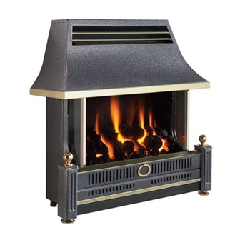
- Page 23 ABOUT YOUR NEW FLAVEL REGENT GAS FIRE The Flavel Regent L.F.E. gas fire incorporates a unique and highly developed fuelbed which gives good flame aeshetics whilst maintaining reasonable running costs. Please take the time to fully read these instructions as you will then be able to obtain the most effective and safe operation of your fire.
- Page 24 OPERATING THE FIRE Light the pilot by depressing the control knob at the “off” position and turn anti-clockwise (with the control depressed) to the second position marked *. When the pilot lights, (pilot can be seen through the right hand side of the fuelbed) hold the control knob down for 10 seconds.
- Page 25 LIGHTING WITH A SPILL Important do not light with a wax taper In the unlikely event of the piezo ignition unit failing to light the fire, turn the control knob to the OFF position, and wait a minute or so for the gas to disperse. The fire can then be lit by using a spill.
- Page 26 Fig. 2 REMOVAL / REFITTING OF THE FUELBED CERAMICS Fit the rear fuelbed section to the combustion chamber, locating behind the support bracket as indicated below in Fig. 3 Fig. 3 Fit rear section of fuelbed behind sup- port bracket as shown Fit the front section of the fuelbed to the combustion chamber, locating behind the front casting as shown overpage in Fig.
- Page 27 Fig. 4 Fuelbed front section fits behind the front casting as shown Refit the dress guard. Due to our policy of continual improvement and development the exact accuracy of descriptions and illustrations cannot be guaranteed Part no. B-66400 Issue 2 CFM Europe Ltd Trentham Lakes Stoke-on-Trent...
- Page 28 Supplied By www.heating spares.co Tel. 0161 620 6677...
Need help?
Do you have a question about the FRLCP0MN and is the answer not in the manual?
Questions and answers