Table of Contents
Advertisement
Quick Links
Advertisement
Table of Contents

Related Manuals for R&S RT-ZC30


Summary of Contents for R&S RT-ZC30
- Page 1 ® R&S RT-ZC30 Current Probe User Manual (>9ÜÖ2) 1409787202 Version 04...
- Page 2 Rohde & Schwarz GmbH & Co. KG. Trade names are trademarks of the owners. ® 1409.7872.02 | Version 04 | R&S RT-ZC30 ® The following abbreviations are used in this manual: R&S RT-ZC30 is abbreviated as R&S RT-ZC30.
-
Page 3: Table Of Contents
® Contents R&S RT-ZC30 Contents 1 Safety and regulatory information........5 1.1 Safety instructions................5 1.2 Labels on the product................7 1.3 Warning messages in the documentation.......... 8 2 Product description...............9 2.1 Product overview.................. 9 2.2 Key features..................9 2.3 Unpacking and checking..............9 2.4 Description of the probe.............. - Page 4 ® Contents R&S RT-ZC30 5.2 Contacting customer support............27 5.3 Returning for servicing..............28 5.4 Calibration interval................28 5.5 Storage and transport................ 29 5.6 Disposal....................29 6 R&S RT-ZA13 probe power supply........31 User Manual 1409.7872.02 ─ 04...
-
Page 5: Safety And Regulatory Information
® Safety and regulatory information R&S RT-ZC30 Safety instructions Safety and regulatory information The product documentation helps you to use the product safely and efficiently. Follow the instructions provided here and in the Chapter 1.1, "Safety instructions", on page 5. - Page 6 ® Safety and regulatory information R&S RT-ZC30 Safety instructions Reconfigure or adjust the product only as described in the product documentation or the data sheet. Any other modifications can affect safety and are not permitted. Never open the casing of the product. Only service personnel authorized by Rohde &...
-
Page 7: Labels On The Product
® Safety and regulatory information R&S RT-ZC30 Labels on the product Working with current probes When working with current probes, you can measure high-frequency currents or currents that contain high-frequency components. ● Switch off the test circuit while connecting the probe. -
Page 8: Warning Messages In The Documentation
® Safety and regulatory information R&S RT-ZC30 Warning messages in the documentation Table 1-2: Labels regarding product and environment safety Labeling in line with EN 50419 for disposal of electrical and electronic equipment after the product has come to the end of its service life. -
Page 9: Product Description
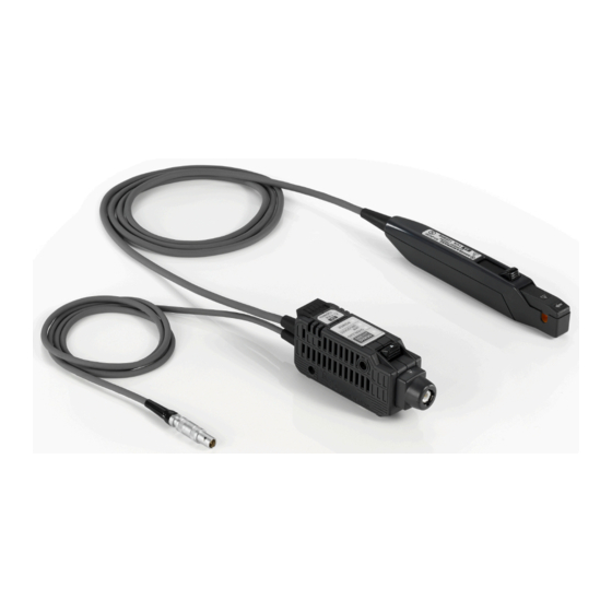
Product description Product overview The R&S RT-ZC30 is an AC/DC current probe. It allows the user to make current measurements from DC to 120 MHz. By clamping on the conductor to be mea- sured, the current waveform is captured easily without interrupting the electric cir- cuit. -
Page 10: Description Of The Probe
® Product description R&S RT-ZC30 Description of the probe Delivery notes The delivery contains the following items: ● User manual ● Carrying case ● R&S RT-Zxx high-voltage and current probes data sheet ● Safety instructions for oscilloscopes and accessories (multilingual) ●... -
Page 11: Terminator
® Product description R&S RT-ZC30 Description of the probe 2.4.2 Terminator Figure 2-2: Terminator overview 1 = Output connector 2 = Unlock lever 3 = Key and LEDs 4 = Ventilation holes 5 = Power plug 6 = Shell 7 = Power supply cord Output connector Connect to the BNC input connector of the waveform measuring instrument. -
Page 12: Sensor
® Product description R&S RT-ZC30 Description of the probe Power plug Connect the plug to the R&S RT-ZA13 probe power supply receptacle to supply power to the sensor. 2.4.3 Sensor RT-ZC30 Figure 2-3: Sensor overview 1 = Current direction indication... -
Page 13: Key And Leds
® Product description R&S RT-ZC30 Description of the probe 2.4.4 Key and LEDs Figure 2-4: Key and LEDs 1 = DEMAG/AUTO ZERO LED 2 = DEMAG/AUTO ZERO Key 3 = OVERLOAD 4 = JAW UNLOCKED LED 5 = POWER LED The key is used to perform demagnetization and zero adjustment, while the LEDs indicate the device status. - Page 14 ® Product description R&S RT-ZC30 Description of the probe Color State ● Slow flashing Before demagnetization and zero adjustment (when either can be per- orange formed) ● After an overload is detected ● When demagnetization terminated abnormally Orange During demagnetization and zero adjustment process...
-
Page 15: Connecting The Probe
Handling the probe Connecting the probe Handling the probe The R&S RT-ZC30 can withstand a moderate amount of physical and electrical stress. To avoid damage, treat the probe with care: ● Prevent the probe from receiving mechanical shock. ● Avoid strain on the probe cable and route it carefully. Keep the cable away from heat sources, as bare conductors could be exposed if the insulation melts. -
Page 16: Connecting The Probe To The Power Supply
Turn off the power switch at the rear of the R&S RT-ZA13 probe power supply. 3. Connect the power cord. 4. Connect the power plug of the R&S RT-ZC30 to the power receptacle of the R&S RT-ZA13 probe power supply. -
Page 17: Connecting The Probe To The Oscilloscope
Insert the terminator of the R&S RT-ZC30 straight into one of the BNC input connectors of the oscilloscope until it clicks. Take care not to tilt it. -
Page 18: Setting Up And Demagnetizing
Setting up and demagnetizing 1. With the waveform measuring instrument input at ground, adjust the waveform to the zero position. 2. Connect the R&S RT-ZC30 current probe to the power supply as described in Chapter 3.2, "Connecting the probe to the power supply", on page 16. -
Page 19: Connecting The Probe To The Dut
4. NOTICE! Risk of circuit damage. Demagnetizing causes current to flow into the conductor, which may damage parts in the circuit to be measured. Do not demagnetize while the R&S RT-ZC30 is clamping a conductor to be mea- sured. Make sure that there is no conductor in the sensor aperture. - Page 20 ® Connecting the probe R&S RT-ZC30 Connecting the probe to the DUT 3. Align the sensor so that the current direction indication matches the direction of current flow through the conductor that you measure. The conductor should be in the center of the clamp aperture because the measurement may be affected by the position within the clamp aperture of the conductor being mea- sured.
-
Page 21: Disconnecting The Probe From The Dut
® Connecting the probe R&S RT-ZC30 Considerations for measurements Disconnecting the probe from the DUT Once measurement has completed: 1. Pull the opening lever toward you. Remove the device from the conductor that you measure. 2. Disconnect the terminator from the waveform measurement instrument. - Page 22 ® Connecting the probe R&S RT-ZC30 Considerations for measurements Continuous input of current exceeding the rated maximum or repeated activa- tion of the safety function may result in damage to the device. ● Even if the input current does not exceed the rated continuous maximum cur- rent, continuous input for an extended period of time may result in activation of the safety circuit to prevent damage resulting from heating of the sensor.
- Page 23 ® Connecting the probe R&S RT-ZC30 Considerations for measurements ● Acoustic resonance can occur depending on the amplitude and frequency of the measured current. This sound may also occur during demagnetizing oper- ation, but it is not a malfunction or probe failure.
- Page 24 ® Connecting the probe R&S RT-ZC30 Considerations for measurements User Manual 1409.7872.02 ─ 04...
-
Page 25: Troubleshooting
® Troubleshooting R&S RT-ZC30 Troubleshooting You can determine the nature of an error by observing the device’s LED. The fol- lowing table explains possible error indications and their cause. Error State Meaning A temperature anomaly has been detected due to heating caused by an overload. - Page 26 ® Troubleshooting R&S RT-ZC30 Error State Meaning When a cur- rent of 0.5 A (RMS) or greater has been detected The device has malfunctioned. Send it to the service center for repair. User Manual 1409.7872.02 ─ 04...
-
Page 27: Maintenance And Service
® Maintenance and service R&S RT-ZC30 Contacting customer support Maintenance and service If service or calibration is needed, contact your Rohde & Schwarz service center. Return a defective product to the Rohde & Schwarz service center for diagnosis and exchange. -
Page 28: Returning For Servicing
Calibration interval Figure 5-1: QR code to the Rohde & Schwarz support page Returning for servicing Use the original packaging to return your R&S RT-ZC30 to your Rohde & Schwarzservice center. A list of all service centers is available on: www.services.rohde-schwarz.com If you cannot use the original packaging, consider the following: 1. -
Page 29: Storage And Transport
® Maintenance and service R&S RT-ZC30 Disposal Storage and transport Protect the product against dust. Ensure that the environmental conditions, e.g. temperature range and climatic load, meet the values specified in the data sheet. Store the product in a shock-resistant case, e.g. in the shipping case. - Page 30 ® Maintenance and service R&S RT-ZC30 Disposal User Manual 1409.7872.02 ─ 04...
-
Page 31: S Rt-Za13 Probe Power Supply
® R&S RT-ZA13 probe power supply R&S RT-ZC30 R&S RT-ZA13 probe power supply This unit is a special-purpose power supply for the current probes. You can connect up to four current probes to the power supply. Front view Rear view... - Page 32 ® R&S RT-ZA13 probe power supply R&S RT-ZC30 User Manual 1409.7872.02 ─ 04...
Need help?
Do you have a question about the RT-ZC30 and is the answer not in the manual?
Questions and answers