
Related Manuals for R&S RT-ZD10


Summary of Contents for R&S RT-ZD10
- Page 1 ® R&S RT‑ZD10/20/30 Active Differential Probe ® R&S RT‑ZA15 External Attenuator User Manual (>:]À2) 1410455002 Version 06...
- Page 2 1410.4550.02 | Version 06 | R&S RT‑ZD10/20/30 Throughout this manual, products from Rohde & Schwarz are indicated without the ® symbol and without product type numbers, e.g. R&S ® RT-ZD10/20/30 is indicated as R&S RT-ZD10/20/30, and R&S ® ProbeMe- ter is indicated as R&S ProbeMeter.
-
Page 3: Table Of Contents
® Contents R&S RT‑ZD10/20/30 Contents 1 Safety and regulatory information........5 1.1 Safety instructions................5 1.2 Labels on the product................7 1.3 Warning messages in the documentation.......... 8 2 Product description...............9 2.1 Key features and key characteristics..........9 2.2 Unpacking and checking..............11 2.3 Description of the probe.............. - Page 4 ® Contents R&S RT‑ZD10/20/30 5.4 Offset compensation................37 5.5 Characteristics of differential probes..........40 5.6 Measurement principles..............44 6 Maintenance and service............ 55 6.1 Cleaning....................55 6.2 Contacting customer support............55 6.3 Returning for servicing..............56 6.4 Calibration interval................56 6.5 Storage and transport................ 57 6.6 Disposal....................
-
Page 5: Safety And Regulatory Information
® Safety and regulatory information R&S RT‑ZD10/20/30 Safety instructions Safety and regulatory information The product documentation helps you to use the product safely and efficiently. Follow the instructions provided here and throughout the manual. Intended use The product is intended for the development, production and verification of elec- tronic components and devices in industrial, administrative, and laboratory envi- ronments. - Page 6 ® Safety and regulatory information R&S RT‑ZD10/20/30 Safety instructions sheet, manuals and the printed "Safety Instructions for Oscilloscopes and Acces- sories" document. If you are unsure about the appropriate use, contact Rohde & Schwarz customer service. Using the product requires specialists or specially trained personnel. These users also need sound knowledge of at least one of the languages in which the user interfaces and the product documentation are available.
-
Page 7: Labels On The Product
® Safety and regulatory information R&S RT‑ZD10/20/30 Labels on the product Consider that the rated voltage depends on the frequency. The voltage limita- tion curves or values are provided in the data sheet. ● Never cause any short circuits when measuring sources with high output cur- rents. -
Page 8: Warning Messages In The Documentation
® Safety and regulatory information R&S RT‑ZD10/20/30 Warning messages in the documentation Warning messages in the documentation A warning message points out a risk or danger that you need to be aware of. The signal word indicates the severity of the safety hazard and how likely it will occur if you do not follow the safety precautions. -
Page 9: Product Description
The external attenuator R&S RT-ZA15 can be used to extend the input voltage range of the R&S RT‑ZD10/20/30. It is supplied with the R&S RT-ZD10 and is available as optional accessory for the R&S RT-ZD20 and R&S RT-ZD30. - Page 10 ® Product description R&S RT‑ZD10/20/30 Key features and key characteristics Operating voltage window ±8 V with ±22 V common mode offset capability (each pin to GND) Available for R&S RT‑ZD10/20/30 probes with serial number ≥ 200000 Maximum non-destructive input voltage ±30 V Between each signal pin and ground Diff.
-
Page 11: Unpacking And Checking
The delivery contains the following items: ● R&S RT‑ZD10/20/30 differential probe ● Carrying case ● Accessory boxes ● R&S RT-ZA15 external attenuator (only with R&S RT-ZD10) ● User manual ● Data sheet ● Calibration certificate ● Documentation of calibration values (if ordered) ●... -
Page 12: Description Of The Probe
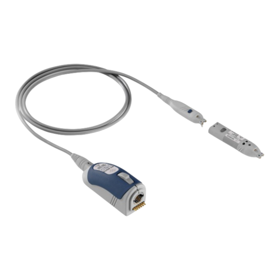
® Product description R&S RT‑ZD10/20/30 Description of the probe Description of the probe The probe consists of the probe head for connection to the DUT, the probe box for connection to the oscilloscope, and the probe cable. 2.3.1 Probe head The small and lightweight probe head is designed for easy handling and high-per- formance measurements. -
Page 13: Accessories And Items
® Product description R&S RT‑ZD10/20/30 Accessories and items 2.3.2 Probe box The probe box connects the probe and the oscilloscope via the Rohde & Schwarz probe interface. The Rohde & Schwarz probe interface contains a male precision 7 mm (276 mil) BNC connector and six pogo pin connectors. This interface pro- vides the required supply voltage and is also used to transmit analog signals and digital data simultaneously. - Page 14 ® Product description R&S RT‑ZD10/20/30 Accessories and items RT-ZA15 External Attenuator Figure 2-1: Available accessories 2.4.1 Accessories supplied The following table shows the accessories supplied with the R&S RT‑ZD10/20/30 differential probe. User Manual 1410.4550.02 ─ 06...
- Page 15 ® Product description R&S RT‑ZD10/20/30 Accessories and items Table 2-1: Accessories supplied Item Quantity Description Signal pin, solder-in Signal pin, variable spacing Browser adapter Adapter, square pin Flex adapter, solder-in, 4 cm / 1.6 in 10 cm / 3.9 in Flex adapter, square pin, 4 cm / 1.6 in 10 cm / 3.9 in...
- Page 16 ® Product description R&S RT‑ZD10/20/30 Accessories and items Item Quantity Description Lead, 15 cm / 5.9 in Mini clip Micro clip Marker band kit External attenuator (only with R&S RT‑ZD10) Adjustment tool (only with R&S RT‑ZD10) Carrying case with foam inlay User Manual 1410.4550.02 ─...
- Page 17 ® Product description R&S RT‑ZD10/20/30 Accessories and items For a list of spare parts, see Chapter 6.7, "Spare parts", on page 57. 2.4.2 Optional accessories If the delivered accessories do not meet individual customer requirements, Rohde & Schwarz offers different accessory sets for sale. The order numbers are provided in the data sheet.
- Page 18 ® Product description R&S RT‑ZD10/20/30 Accessories and items Table 2-5: Optional adapters Accessories Items Quantity R&S RT‑ZA9 probe box to N / USB adapter The adapter connects the R&S RT‑ZD10/20/30 differential probe to any other oscilloscope or any other measurement instrument (e.g. a net- work or spectrum analyzer).
- Page 19 ® Product description R&S RT‑ZD10/20/30 Accessories and items Table 2-6: Service accessories Item Description R&S RT-ZK2 The service kit is used to calibrate the probe, to do perfor- mance tests, and for servicing. The service kit includes all adapters and accessories to connect the probe to the required measuring instruments.
-
Page 20: Connecting The Probe
® Connecting the probe R&S RT‑ZD10/20/30 Connecting the probe to the oscilloscope Connecting the probe Handling the probe The R&S RT‑ZD10/20/30 can withstand a moderate amount of physical and elec- trical stress. To avoid damage, treat the probe with care: ●... -
Page 21: Identification Of The Probe
® Connecting the probe R&S RT‑ZD10/20/30 Identification of the probe Connect the probe box (1) to the Rohde & Schwarz probe interface of the oscilloscope (2). The probe snaps in when connected properly to the port. Figure 3-1: Connecting the probe to the Rohde & Schwarz oscilloscope ►... -
Page 22: Connecting The Probe To The Dut
® Connecting the probe R&S RT‑ZD10/20/30 Connecting the probe to the DUT The complete probe information is shown in the probe settings dialog. For more information, refer to the user manual of your oscilloscope. Connecting the probe to the DUT This chapter describes the different ways of connecting the probe to the DUT. - Page 23 ® Connecting the probe R&S RT‑ZD10/20/30 Connecting the probe to the DUT Pins Signal pin, solder-in The fine wires on the pins are best suited to making secure contact with small contact points, such as SMT components or IC pins. The wires have an insulating finish to prevent unwanted shorts.
- Page 24 ® Connecting the probe R&S RT‑ZD10/20/30 Connecting the probe to the DUT Adapters Adapter, square pin The square pin adapter is used for plugging the probe onto pin strips with a pitch of 2.54 mm (100 mil). Distance range: 2.54 mm (100 mil) Browser adapter The spring-loaded browser adapter allows handheld probing with maximum convenience.
- Page 25 ® Connecting the probe R&S RT‑ZD10/20/30 Connecting the probe to the DUT Flex adapter, solder-in The flex adapter well suited for creating solid contact with test points that are hard to reach (e.g. between two inserted boards). The flex adapter reduces the probe rise time, but is designed to ensure optimum settling.
- Page 26 ® Connecting the probe R&S RT‑ZD10/20/30 Connecting the probe to the DUT Leads and clips Short and long lead The lead provides a flexible connection to the DUT. It is plugged onto a pin on the DUT and connected to the signal sockets or the ground socket. In addition, you can use micro and mini clips with the leads.
- Page 27 ® Connecting the probe R&S RT‑ZD10/20/30 Connecting the probe to the DUT Micro clip The micro clip is designed for probing IC pins and thin wires in fine-pitch applications. ● Clamp the micro clip to a pin. ● Connect it directly to the signal socket, or use a lead to connect it to the signal socket or the ground socket.
-
Page 28: S Rt-Za15 External Attenuator
Attenuation 100:1 Bandwidth DC to 1.0 GHz (with R&S RT-ZD10) DC to 1.5 GHz (with R&S RT-ZD20) DC to 2.0 GHz (with R&S RT-ZD30) Dynamic range (differential input) ±50 V with ±50 V offset capability Differential input resistance 1 MΩ... -
Page 29: Inserting The Probe
® R&S RT-ZA15 external attenuator R&S RT‑ZD10/20/30 Inserting the probe ‑ ZD10/20/30 Figure 4-1: R&S RT-ZA15 external attenuator with inserted R&S RT 1 = Positive signal socket 2 = Negative signal socket 3 = Ground socket 4 = Trimmer for DC common mode rejection 5 = Trimmer for pulse response of positive input 6 = Trimmer for pulse response of negative input 7 = Notch for micro button... -
Page 30: Adjusting
® R&S RT-ZA15 external attenuator R&S RT‑ZD10/20/30 Adjusting 3. Press the probe gently into the attenuator until the micro button matches the notch on the attenuator in a central position. 4. The oscilloscope does not detect the external attenuator automatically. To adjust the scaling for display, R&S ProbeMeter and offsets, select the attenua- tor in the probe setup of the oscilloscope. - Page 31 ® R&S RT-ZA15 external attenuator R&S RT‑ZD10/20/30 Adjusting During the following procedure, both signal sockets (positive and negative) are connected to the Hi output of the DC voltage source. The ground socket is con- nected to the Lo output of the DC voltage source. 1.
- Page 32 ® R&S RT-ZA15 external attenuator R&S RT‑ZD10/20/30 Adjusting ● Vertical scale = 100 mV/div ● Trigger source = C1, Trigger mode = Auto, Run cont ● Acquisition mode: Decimation = High res, Arithmetic = Average, Average count/N-single count = 10 ●...
- Page 33 ® R&S RT-ZA15 external attenuator R&S RT‑ZD10/20/30 Adjusting 4. Set up the oscilloscope: ● Horizontal scale = 1 µs/div ● Bandwidth = 20 MHz ● Trigger source = C1, Trigger mode = Auto, Run cont ● Trigger level = 500 mV, Trigger slope = Positive ●...
- Page 34 ® R&S RT-ZA15 external attenuator R&S RT‑ZD10/20/30 Adjusting 4. Using the adjustment tool, turn the trimmer for pulse response of the negative input until an optimum square wave response is visible on the oscilloscope screen. User Manual 1410.4550.02 ─ 06...
-
Page 35: Features And Characteristics Of R&S Rt-Zd10/20/30 Probes
® Features and characteristics of R&S RT‑ZD10/20/30 R&S RT‑ZD10/20/30 probes Zero adjustment Features and characteristics of R&S RT‑ZD10/20/30 probes Zero adjustment The zero error can impair the measurement results, therefore, correct the zero error if necessary. The zero error of the probe itself is very small. However, differences in DUT and oscilloscope ground levels can cause larger zero errors visible on the oscilloscope's screen. -
Page 36: Micro Button
® Features and characteristics of R&S RT‑ZD10/20/30 R&S RT‑ZD10/20/30 probes R&S ProbeMeter Micro button The micro button provides easy and quick access to important functions of the Rohde & Schwarz oscilloscope. After a function has been assigned, pressing the micro button remotely controls this specific function on the base unit. For exam- ple, "Run continuous"... -
Page 37: Offset Compensation
® Features and characteristics of R&S RT‑ZD10/20/30 R&S RT‑ZD10/20/30 probes Offset compensation ● Independent of oscilloscope settings for position, vertical scale, horizontal scale, and trigger. ● Unique way to detect unexpected or inadmissible common mode voltages, e.g. bias points - measurement of common mode DC voltages without recon- necting the probe. - Page 38 ® Features and characteristics of R&S RT‑ZD10/20/30 R&S RT‑ZD10/20/30 probes Offset compensation Figure 5-1: Differential offset compensation for a single-ended measurement (negative ‑ ZD10/20/30 input connected to ground) using an R&S RT There are several ways to set the offset compensation: ●...
- Page 39 ® Features and characteristics of R&S RT‑ZD10/20/30 R&S RT‑ZD10/20/30 probes Offset compensation Figure 5-2: Common mode (CM) offset compensation for a differential measurement If the input signals fit into the operating voltage window of the R&S RT‑ZD10/20/30, it is not necessary to set a common mode offset compensa- tion.
-
Page 40: Characteristics Of Differential Probes
® Features and characteristics of R&S RT‑ZD10/20/30 R&S RT‑ZD10/20/30 probes Characteristics of differential probes If supported by the Rohde & Schwarz oscilloscope, you can set the "CM offset" in the probe settings on the instrument. For more details, see the oscilloscope's user manual. - Page 41 ® Features and characteristics of R&S RT‑ZD10/20/30 R&S RT‑ZD10/20/30 probes Characteristics of differential probes Typically, the differential and the common mode input voltages are used to describe the behavior of a differential probe. The output voltage V , which is displayed on the base unit, is obtained by super- imposing the voltages generated from the differential mode input voltage and from the common mode input voltage:...
- Page 42 ® Features and characteristics of R&S RT‑ZD10/20/30 R&S RT‑ZD10/20/30 probes Characteristics of differential probes A high CMRR is important if significant common mode signals are encountered at the probe input, for example: ● DC voltages for setting the operating points of active DUTs ●...
- Page 43 ® Features and characteristics of R&S RT‑ZD10/20/30 R&S RT‑ZD10/20/30 probes Characteristics of differential probes Figure 5-4: Operating voltage window Signal clipping Only differential input signals are detected by the probe and displayed by the base unit. Common mode signals are suppressed by the probe. Therefore, the user does not initially recognize that the operating voltage window is exceeded owing to inadmissible common mode voltages.
-
Page 44: Measurement Principles
® Features and characteristics of R&S RT‑ZD10/20/30 R&S RT‑ZD10/20/30 probes Measurement principles The ground connection can also affect the CMRR of the probe. Problems with unwanted common mode signals can often be improved by adding a ground con- nection. Measurement principles The R&S RT‑ZD10/20/30 differential probe provides an electrical connection between the DUT and the oscilloscope. - Page 45 ® Features and characteristics of R&S RT‑ZD10/20/30 R&S RT‑ZD10/20/30 probes Measurement principles ‑ ZD10/20/30 probe Figure 5-5: Equivalent circuit model of the R&S RT Table 5-1: Designations Abbreviation Description Differential voltage between the test point without probe connected Differential voltage at the test point with probe connected, corre- sponds to the input voltage of the probe Differential source resistance of the DUT Differential load resistance of the DUT...
- Page 46 ® Features and characteristics of R&S RT‑ZD10/20/30 R&S RT‑ZD10/20/30 probes Measurement principles width. The following explanations refer to the probe itself, but can also be applied to the entire system. ‑ ZD10/20/30 Figure 5-6: Amplitude frequency response of the R&S RT The bandwidth: ●...
- Page 47 ® Features and characteristics of R&S RT‑ZD10/20/30 R&S RT‑ZD10/20/30 probes Measurement principles In addition to bandwidth, a constant amplitude frequency response of the probe is decisive for high signal integrity. The Figure 5-6 shows the typical amplitude fre- quency response of an R&S RT‑ZD10/20/30 differential probe. All frequency com- ponents are transferred with the same gain so that the input signal is displayed without distortion.
- Page 48 R&S RT-ZD30. For an R&S RT-ZD20, typical bandwidth and rise time values are smaller and limited to 1.5 GHz or 250 ps, respectively. For an R&S RT-ZD10, typical bandwidth and rise time values are also smaller and limited to 1.0 GHz or 350 ps, respectively.
- Page 49 ® Features and characteristics of R&S RT‑ZD10/20/30 R&S RT‑ZD10/20/30 probes Measurement principles User Manual 1410.4550.02 ─ 06...
- Page 50 ® Features and characteristics of R&S RT‑ZD10/20/30 R&S RT‑ZD10/20/30 probes Measurement principles 5.6.1.3 CMRR The CMRR is very good for low-frequency signals, but it continuously decreases for higher frequencies. Therefore, the CMRR is usually specified as a function of frequency. Figure 5-9 shows a typical CMRR for an R&S RT‑ZD10/20/30 differential probe with a very symmetrical connection to the DUT.
- Page 51 ® Features and characteristics of R&S RT‑ZD10/20/30 R&S RT‑ZD10/20/30 probes Measurement principles impedance between its positive (+) and the negative (-) signal socket. The result- ing input impedance versus frequency is indicated in Figure 5-10. ‑ ZD10/20/30 Figure 5-10: Magnitude of the differential input impedance of the R&S RT probe as a function of frequency The differential input impedance varies greatly versus the frequency and is defined by the following values:...
- Page 52 ® Features and characteristics of R&S RT‑ZD10/20/30 R&S RT‑ZD10/20/30 probes Measurement principles RF resistance R The RF resistance R determines the minimum input impedance and thus the maximum loading at very high frequencies above 1.0 GHz. Thus, the measure- ment result depends on the source impedance of the DUT. The RF resistance R prevents the input voltage from rising immediately to its final value in the case of fast transients.
- Page 53 ® Features and characteristics of R&S RT‑ZD10/20/30 R&S RT‑ZD10/20/30 probes Measurement principles ● For single-ended input signals, the input impedance is the impedance between the positive or negative signal socket and the ground socket. ● For common mode input signals, the input impedance is the impedance between the parallel connection of the positive and negative signal sockets and the ground socket.
- Page 54 ® Features and characteristics of R&S RT‑ZD10/20/30 R&S RT‑ZD10/20/30 probes Measurement principles to and from the frequency domain. Probe manufacturers use one or the other of these two approaches. Rohde & Schwarz has decided in favor of the user-friendly approach. In our opin- ion, most users want to know the signal present in the DUT before it was altered by the influence of the probe.
-
Page 55: Maintenance And Service
® Maintenance and service R&S RT‑ZD10/20/30 Contacting customer support Maintenance and service Like all Rohde & Schwarz products, Rohde & Schwarz probes and adapters are of high quality and require only minimum service and repair. However, if service or calibration is needed, contact your Rohde & Schwarz service center. Return a defective product to the Rohde &... -
Page 56: Returning For Servicing
® Maintenance and service R&S RT‑ZD10/20/30 Calibration interval Figure 6-1: QR code to the Rohde & Schwarz support page Returning for servicing Use the original packaging to return your R&S RT‑ZD10/20/30 to your Rohde & Schwarzservice center. A list of all service centers is available on: www.services.rohde-schwarz.com If you cannot use the original packaging, consider the following: 1. -
Page 57: Storage And Transport
® Maintenance and service R&S RT‑ZD10/20/30 Spare parts Storage and transport Protect the product against dust. Ensure that the environmental conditions, e.g. temperature range and climatic load, meet the values specified in the data sheet. Store the product in a shock-resistant case, e.g. in the shipping case. Unless otherwise specified in the data sheet, the maximum transport altitude with- out pressure compensation is 4500 m above sea level. - Page 58 ® Maintenance and service R&S RT‑ZD10/20/30 Spare parts Table 6-1: Accessories spare parts Pos Item Description Material Number Signal pin, solder-in 1417.0538.00 Signal pin, variable spacing 1417.0550.00 Browser adapter 1417.0509.00 Adapter, square pin 1417.0573.00 Flex adapter, solder-in, 1417.0596.00 4 cm / 1.6 in 10 cm / 3.9 in Flex adapter, square pin, 1417.0580.00...
- Page 59 ® Maintenance and service R&S RT‑ZD10/20/30 Spare parts Pos Item Description Material Number Lead, 6 cm / 2.4 in 1416.0128.00 Lead, 15 cm / 5.9 in 1416.0134.00 Mini clip 1416.0105.00 Micro clip 1416.0111.00 Marker band kit 1416.0205.00 External attenuator 1410.4744.02 Adjustment tool 1416.0057.00 User Manual 1410.4550.02 ─...
- Page 60 ® Maintenance and service R&S RT‑ZD10/20/30 Spare parts Pos Item Description Material Number Pogo pin Pogo pin connector, 6 pins 3584.6396.00 R&S RT-ZK2 R&S RT-ZK2 service kit 1410.5305.02 Table 6-2: Parts for ESD prevention Pos. Item Material number ESD wrist strap 0008.9959.00 ESD grounding cable 1043.4962.00...
-
Page 61: Functional Check
® Functional check R&S RT‑ZD10/20/30 Functional check The functional check confirms the basic operation of the R&S RT‑ZD10/20/30 dif- ferential probe. The functional check is not suitable for verifying compliance with the probe specifications. 1. Connect the R&S RT‑ZD10/20/30 to a Rohde & Schwarz oscilloscope as described in Chapter 3.2, "Connecting the probe to the oscilloscope",...
Need help?
Do you have a question about the RT-ZD10 and is the answer not in the manual?
Questions and answers