
Related Manuals for R&S RT-ZC20


Summary of Contents for R&S RT-ZC20
- Page 1 Allice Messtechnik GmbH ® R&S RT-ZC20 Current Probe User Manual (>9Ü>2) 1409781402 Version 03...
- Page 2 Trade names are trademarks of the owners. ® 1409.7814.02 | Version 03 | R&S RT-ZC20 The following abbreviations are used in this manual: R&S ® RT-ZC20 is abbreviated as R&S RT-ZC20, and ® R&S RT-ZA13 is abbreviated as R&S RT-ZA13.
-
Page 3: Table Of Contents
Allice Messtechnik GmbH ® Contents R&S RT-ZC20 Contents 1 Notes on Safety..............5 2 Product Description............10 2.1 Product Overview................10 2.2 Key Features..................10 2.3 Inspecting the Contents..............10 2.4 Description of the Probe..............11 3 Putting into Operation............13 3.1 Preparing the Measurement...............13... - Page 4 Allice Messtechnik GmbH ® Contents R&S RT-ZC20 User Manual 1409.7814.02 ─ 03...
-
Page 5: Notes On Safety
Notes on Safety R&S RT-ZC20 Notes on Safety Thank you for purchasing the R&S RT-ZC20 current probe. To obtain maximum performance from the device, please read this manual first, and keep it handy for future reference. Risk of physical injury This device is designed to comply with IEC 61010 Safety Standards, and has been thoroughly tested for safety before shipment. - Page 6 Allice Messtechnik GmbH ® Notes on Safety R&S RT-ZC20 Risk of fatal injury ● To avoid electric shock and short circuits, never attach the clamp to bare, unisolated conductors. Make sure to measure at a location on an insulated wire where the insu- lation is sufficient for the circuit voltage.
- Page 7 Allice Messtechnik GmbH ® Notes on Safety R&S RT-ZC20 Risk of fatal injury ● This device is made for use with the R&S RT-ZA13 probe power supply. ● When using a measurement instrument that does not provide isolation between its input terminals and chassis or other input terminals, please pay attention to the following points.
- Page 8 Allice Messtechnik GmbH ® Notes on Safety R&S RT-ZC20 Risk of instrument damage ● To avoid damage to the device, protect it from vibration or shock during transport and handling, and be especially careful to avoid dropping. ● This device should be installed and operated indoors only, between 0°C and 40°C (32°F to 104°F) and 80% RH or less.
- Page 9 Allice Messtechnik GmbH ® Notes on Safety R&S RT-ZC20 ● To avoid damaging the sensor cable and power supply cable, do not bend or pull the cables. ● Avoid stepping on or pinching the cable, which could damage the cable insulation.
-
Page 10: Product Description
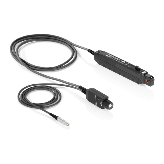
Product Description Product Overview The R&S RT-ZC20 is an AC/DC current probe. It allows the user to make current measurements from DC to 100 MHz. By clamping on the conductor to be mea- sured, the current waveform is captured easily without interrupting the electric cir- cuit. -
Page 11: Description Of The Probe
Allice Messtechnik GmbH ® Product Description R&S RT-ZC20 Description of the Probe The following accessories are delivered with the probe: ● User manual ● Carrying case ● R&S RT-Zxx data sheet ● Calibration certificate ● Documentation of calibrated values... - Page 12 Allice Messtechnik GmbH ® Product Description R&S RT-ZC20 Description of the Probe 10 = Zero adjustment dial (ZERO ADJ) 11 = Coarse adjustment trimmer 12 = Output connector 13 = Power plug Sensor head The sensor head clamps on the conductor being measured, and carries out the actual current measurement.
-
Page 13: Putting Into Operation
1. Have the R&S RT-ZA13 probe power supply, and an oscilloscope or waveform measuring instrument ready. 2. Turn off the power switch. Connect the power cord. 3. Connect the power plug of the R&S RT-ZC20 to the power receptacle of the R&S RT-ZA13 probe power supply. User Manual 1409.7814.02 ─ 03... - Page 14 5. Turn on the power switch R&S RT-ZA13 probe power supply. Ensure that the front panel power indicator lights. 6. Connect the output connector of the R&S RT-ZC20 to one of the BNC input connectors of the oscilloscope. Turn the collar until it clicks, and check that it is locked securely.
-
Page 15: Connecting The Probe To The Oscilloscope
Allice Messtechnik GmbH ® Putting into Operation R&S RT-ZC20 Connecting the Probe to the Oscilloscope Connecting the Probe to the Oscilloscope ► Connect the probe box (1) to the Rohde & Schwarz probe interface of the oscilloscope (2). The probe snaps in when connected properly to the port. -
Page 16: Demagnetizing And Zero Adjustment
Demagnetizing and Zero Adjustment Risk of circuit damage ● Do not demagnetize while the R&S RT-ZC20 is clamping a conductor to be measured. Demagnetizing causes current to flow into the conductor, which may damage parts in the circuit to be measured. -
Page 17: Connecting The Probe To The Dut
Allice Messtechnik GmbH ® Putting into Operation R&S RT-ZC20 Connecting the Probe to the DUT 7. If zero adjustment is not possible, turn the coarse adjustment trimmer to bring the trace within the range of adjustment by the zero adjustment dial, see Chapter 2.4, "Description of the... - Page 18 Allice Messtechnik GmbH ® Putting into Operation R&S RT-ZC20 Connecting the Probe to the DUT 4. Press the opening lever until the UNLOCK indication disappears. Make sure that the sensor head is properly closed. If the sensor head is not properly closed, accurate measurement is not possi- ble.
- Page 19 Allice Messtechnik GmbH ® Putting into Operation R&S RT-ZC20 Connecting the Probe to the DUT Risk of instrument damage due to continuous input current ● The maximum continuous input range is based on heat that is internally generated during measurement. Always keep the input current below this level.
- Page 20 Allice Messtechnik GmbH ® Putting into Operation R&S RT-ZC20 Connecting the Probe to the DUT Risk of instrument damage due to continuous input current ● At high ambient temperatures, the built-in safety circuit may activate at current input levels below the rated continuous maximum current.
- Page 21 Allice Messtechnik GmbH ® Putting into Operation R&S RT-ZC20 Connecting the Probe to the DUT ● Immediately after powering on, this device may be subject to an appre- ciable offset drift due to the effect of self-heating. To counteract this, allow the device to warm up for about 30 minutes before carrying out measurements.
- Page 22 Allice Messtechnik GmbH ® Putting into Operation R&S RT-ZC20 Connecting the Probe to the DUT At high frequencies, common mode noise may affect measurements taken on the high voltage side of circuits. If this occurs, reduce the frequency range of the waveform measuring instrument, or clamp onto the low-voltage side of the circuit, as appropriate.
-
Page 23: Maintenance And Service
Allice Messtechnik GmbH ® Maintenance and Service R&S RT-ZC20 Contacting Customer Support Maintenance and Service If service or calibration is needed, contact your Rohde & Schwarz service center. Return a defective product to the Rohde & Schwarz service center for diagnosis and exchange. -
Page 24: Returning For Servicing
Figure 4-1: QR code to the Rohde & Schwarz support page Returning for Servicing Use the original packaging to return your R&S RT-ZC20 to your Rohde & Schwarz service center. A list of all service centers is available on: www.services.rohde-schwarz.com If you cannot use the original packaging, consider the following: 1. -
Page 25: Discarding The Product
Allice Messtechnik GmbH ® Maintenance and Service R&S RT-ZC20 Discarding the Product Discarding the Product Handle and dispose the product in accordance with local regulations. User Manual 1409.7814.02 ─ 03... -
Page 26: S Rt-Za13 Probe Power Supply
Allice Messtechnik GmbH ® R&S RT-ZA13 Probe Power Supply R&S RT-ZC20 R&S RT-ZA13 Probe Power Supply This unit is a special-purpose power supply for the current probes. You can connect up to four current probes to the power supply. Front view Rear view User Manual 1409.7814.02 ─...
Need help?
Do you have a question about the RT-ZC20 and is the answer not in the manual?
Questions and answers