Table of Contents
Advertisement
Quick Links
Advertisement
Table of Contents

Related Manuals for R&S RT-Z


Summary of Contents for R&S RT-Z
- Page 1 ® R&S RT-ZS60 Active Voltage Probe User Manual (>B×Z2) 1418734202...
- Page 2 ® This user manual describes the following R&S RT-ZS models and options: ● R&S ® RT-ZS60 (1418.7307.02) © 2019 Rohde & Schwarz GmbH & Co. KG Mühldorfstr. 15, 81671 München, Germany Phone: +49 89 41 29 - 0 Fax: +49 89 41 29 12 164 Email: info@rohde-schwarz.com Internet:...
- Page 3 Safety Instructions Instrucciones de seguridad Risk of injury and instrument damage The instrument must be used in an appropriate manner to prevent personal injury or instrument damage. ● Do not open the instrument casing. ● Read and observe the "Basic Safety Instructions" delivered as printed brochure with the instrument.
- Page 4 Safety Instructions - Informaciones de seguridad Safety Instructions for Active Voltage Probes When handling active voltage probes, the following basic rules must be observed. Prior to using an active voltage probe, read the applicable manual including the safety instructions. Keep the safety instructions and the product documentation in a safe place and pass them on to other users.
- Page 5 Instructions - Instrucciones Instructions for Electrostatic Discharge Protection Risk of damaging electronic components To avoid damage of electronic components, the operational site must be protected against electrostatic discharge (ESD). Wrist strap with cord Floor mat Heel strap Ground connection of operational site The following two methods of ESD protection may be used together or separately: , Wrist strap with cord to ground connection...
- Page 6 Customer Support Technical support – where and when you need it For quick, expert help with any Rohde & Schwarz equipment, contact one of our Customer Support Centers. A team of highly qualified engineers provides telephone support and will work with you to find a solution to your query on any aspect of the operation, programming or applications of Rohde &...
-
Page 7: Table Of Contents
® Contents R&S RT-ZS60 Contents 1 Product Description.............. 5 1.1 Key Features and Key Characteristics..........5 1.1.1 Key Characteristics................. 5 1.1.2 Key Features...................6 1.2 Unpacking....................7 1.2.1 Inspecting the Contents................7 1.3 Description of the Probe..............8 1.3.1 Probe Head.....................8 1.3.2 Probe Box....................9 1.4 Accessories and Items................. - Page 8 ® Contents R&S RT-ZS60 4.1.1 Bandwidth..................... 27 4.1.2 Connection Inductance................. 29 4.1.3 Performance with Different Connection Types........30 4.2 Signal Loading of the Input Signal............ 32 4.2.1 Input Impedance................... 32 4.3 Probing Philosophy................35 5 Maintenance and Service............37 5.1 Service Strategy..................37 5.2 Returning for Servicing..............
-
Page 9: Product Description
® Product Description R&S RT-ZS60 Key Features and Key Characteristics Product Description Key Features and Key Characteristics The R&S RT-ZS60 is a single-ended active voltage probe with high input impe- dance. It is used for ground-referenced voltage measurements from DC to 6 GHz. The R&S RT-ZS60 is optimized for single-ended measurements in environments characterized by 50 Ω... -
Page 10: Key Features
® Product Description R&S RT-ZS60 Key Features and Key Characteristics Bandwidth DC to 6 GHz Dynamic range ±8 V with ±10 V offset capability 16 V AC (V Maximum non-destructive input voltage ±30 V Input resistance 1 MΩ Input capacitance 0.3 pF R&S ProbeMeter, measurement error <0.1 %... -
Page 11: Unpacking
® Product Description R&S RT-ZS60 Unpacking Unpacking The carrying case contains the following items: ● R&S RT-ZS60 active voltage probe ● Carrying case ● Accessory boxes ● User manual ● R&S RT-ZS60 data sheet ● Calibration certificate ● Documentation of calibration values (if ordered) 1.2.1 Inspecting the Contents... -
Page 12: Description Of The Probe
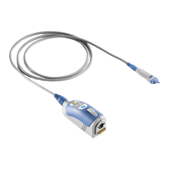
® Product Description R&S RT-ZS60 Description of the Probe Description of the Probe The probe consists of the probe head for connection to the DUT, the probe box for connection to the oscilloscope, and the probe cable. 1.3.1 Probe Head The small and lightweight probe head is designed for easy handling and high-per- formance measurements. -
Page 13: Probe Box
® Product Description R&S RT-ZS60 Accessories and Items Special accessories for signal socket The signal socket of the R&S RT-ZS60 has a special design to ensure opti- mal performance. The signal socket is not compatible to standard accesso- ries based on 0.64 mm (25 mil) square pins or 0.8 mm (35 mil) round pins. Use only special accessories for R&S RT-ZS60 provided by Rohde &... -
Page 14: Accessories Supplied
® Product Description R&S RT-ZS60 Accessories and Items marker band kit lead, 15 cm / 5.9 in lead 6 cm / 2.4 in ground adapter, square pin ground pin, pogo ground pin, solder in signal adapter, square pin signal pin micro clip signal pin, solder in mini clip... - Page 15 ® Product Description R&S RT-ZS60 Accessories and Items Item Quantity Description Signal adapter, square pin Ground pin, solder in Ground pin, pogo Ground adapter, square pin Lead, 6 cm / 2.4 in Lead, 15 cm / 5.9 in Mini clip User Manual 1418.7342.02 ─...
-
Page 16: Optional Accessories
® Product Description R&S RT-ZS60 Accessories and Items Item Quantity Description Micro clip Marker band kit Carrying case with foam inlay For a list of spare parts, see Chapter 5.6, "Spare Parts", on page 38. 1.4.2 Optional Accessories If the delivered accessories do not meet individual customer requirements, Rohde &... -
Page 17: Service Accessories
® Product Description R&S RT-ZS60 Accessories and Items Table 1-4: R&S RT-ZA6 lead set Item Quantity Description Lead, 6 cm / 2.4 in Contains short and long leads. Lead, 15 cm / 5.9 in Table 1-5: R&S RT-ZA9 probe box to N / USB adapter The adapter can be used to connect the R&S RT- ZS60 active voltage probe to any other oscilloscope or any other measurement instrument (e.g. -
Page 18: Putting Into Operation
® Putting into Operation R&S RT-ZS60 Putting into Operation The probe is designed for usage with oscilloscopes that have a Rohde & Schwarz probe interface. Supported Rohde & Schwarz oscilloscopes are listed in the pro- be's data sheet. Read and observe the "Basic Safety Instructions" that are delivered with the probe as a printed brochure. -
Page 19: Connecting The Probe To The Oscilloscope
® Putting into Operation R&S RT-ZS60 Connecting the Probe to the Oscilloscope During usage, the probe slightly heats up. Warming is normal behavior and not a sign of malfunction. Damage caused by electrostatic discharge Electrostatic discharge (ESD) can damage the electronic components of the probe and the instrument, and also the device under test (DUT). -
Page 20: Identification Of The Probe
® Putting into Operation R&S RT-ZS60 Using the Probe ► To disconnect the probe: a) Press and hold the release button (3). b) Pull the probe box away from the oscilloscope. Identification of the Probe When the probe is connected to the oscilloscope, the oscilloscope recognizes the probe and reads out the probe-specific parameters. -
Page 21: Micro Button
® Putting into Operation R&S RT-ZS60 Using the Probe 4. Adjust the zero position of the waveform using the appropriate function of the oscilloscope ("AutoZero", "Zero Adjust" or similar). The waveform is set to 0 V on the horizontal centerline of the oscilloscope. 2.3.2 Micro Button The micro button provides easy and quick access to important functions of the... -
Page 22: R&S Probemeter
® Putting into Operation R&S RT-ZS60 Using the Probe Figure 2-2: Offset compensation voltage and dynamic range There are several ways to set the offset compensation: ● Use the vertical knob at the oscilloscope if its function is set to offset. ●... - Page 23 ® Putting into Operation R&S RT-ZS60 Using the Probe High-precision measurements are achieved through immediate digitization of the measured DC voltage at the probe tip. When the R&S ProbeMeter is active, the measured values are displayed on the oscilloscope. The R&S ProbeMeter state is part of the probe settings of the chan- nel to which the probe is connected.
-
Page 24: Connecting The Probe To The Dut
® Connecting the Probe to the DUT R&S RT-ZS60 Connecting the Probe to the DUT This chapter describes the different ways of connecting the probe to the DUT. In addition, the usage of the supplied accessories is explained. To achieve optimum RF performance, the connections must be as short as possi- ble. - Page 25 ® Connecting the Probe to the DUT R&S RT-ZS60 Signal pin, solder in, and ground pin, solder-in Using two solder-in pins for ground and signal, the R&S RT-ZS60 is soldered directly into the circuit. The pins can be exchanged on the probe and can remain in the circuit.
- Page 26 ® Connecting the Probe to the DUT R&S RT-ZS60 Signal adapter, square pin, and ground adapter, square pin Using two square-in pin adapters for ground and signal, the probe can be connected directly to a pin strip. The sockets are compatible with 0.64 mm (25 mil) square pins and 0.6 mm to 0.8 mm (24 mil to 35 mil) round pins.
- Page 27 ® Connecting the Probe to the DUT R&S RT-ZS60 Leads Short and long lead The lead provides a flexible connection to the DUT. It is plugged onto a pin on the DUT and can be used to connect either the signal socket or the ground socket.
- Page 28 ® Connecting the Probe to the DUT R&S RT-ZS60 Clips Mini and micro clips The mini clip is designed for probing large IC pins, wires and through-hole components. The micro clip is designed for probing IC pins and thin wires in fine-pitch applications. Clips can be used to contact ground and sig- nal.
-
Page 29: Measurement Principles
® Measurement Principles R&S RT-ZS60 Measurement Principles The R&S RT-ZS60 active voltage probe provides an electrical connection between the DUT and the oscilloscope. The probe transfers the voltage of the electrical signal tapped off the DUT to the oscilloscope, where it is displayed graphically. - Page 30 ® Measurement Principles R&S RT-ZS60 Figure 4-1: Equivalent circuit model of the R&S RT-ZS60 probe Table 4-1: Designations Abbreviation Description Voltage at the test point without probe connected Voltage at the test point with probe connected, corresponds to the input voltage of the probe Source resistance of the DUT Load resistance of the DUT DC input resistance...
-
Page 31: Signal Integrity Of The Transferred Signal
® Measurement Principles R&S RT-ZS60 Signal Integrity of the Transferred Signal Signal Integrity of the Transferred Signal The following sections describe the effect that bandwidth and connection induc- tance have on signal integrity. 4.1.1 Bandwidth The bandwidth BW of a probe is one of its specific parameters. The bandwidth of the probe and the bandwidth of the base unit together form the system band- width. - Page 32 ® Measurement Principles R&S RT-ZS60 Signal Integrity of the Transferred Signal ● Specifies the transferable spectrum for other waveforms. E.g., with square wave signals, the fifth harmonic should still be within the bandwidth for a high signal integrity. ● Determines the minimum measurable signal rise time. The rise time t of the rise probe is inversely proportional to its bandwidth.
-
Page 33: Connection Inductance
® Measurement Principles R&S RT-ZS60 Signal Integrity of the Transferred Signal 4.1.2 Connection Inductance The connection inductance L is caused by connecting the probe to the DUT. In contrast to the probe-specific bandwidth, the connection inductance mainly depends on the selected type. The connection inductance: ●... -
Page 34: Performance With Different Connection Types
® Measurement Principles R&S RT-ZS60 Signal Integrity of the Transferred Signal 4.1.3 Performance with Different Connection Types Table 4-2 shows three types of connection between probe and DUT as well as the associated rise times, bandwidths, input impedances and overshoots. Table 4-2: Typical rise time, bandwidth, input impedance and overshoot with different connection types Connection... - Page 35 ® Measurement Principles R&S RT-ZS60 Signal Integrity of the Transferred Signal Figure 4-5: Step response of the R&S RT-ZS60 with a type 1 connection Figure 4-6: Step response of the R&S RT-ZS60 with a type 2 connection User Manual 1418.7342.02 ─ 04...
-
Page 36: Signal Loading Of The Input Signal
® Measurement Principles R&S RT-ZS60 Signal Loading of the Input Signal Figure 4-7: Step response of the R&S RT-ZS60 with a type 3 connection Signal Loading of the Input Signal The previous section dealt with the transfer function and step response of the probe. - Page 37 ® Measurement Principles R&S RT-ZS60 Signal Loading of the Input Signal The resulting input impedance versus frequency is indicated in Figure 4-8. The trace shows five characteristic areas, which can be assigned to R and |Z |. The resulting loading of a step signal at the input of the probe is given Figure 4-9.
- Page 38 ® Measurement Principles R&S RT-ZS60 Signal Loading of the Input Signal Figure 4-9: Signal loading caused by the R&S RT-ZS60 probe at an effective source impe- dance of 25 Ω 4.2.1.1 Input Resistance The input resistance R determines the loading of the DUT at DC and low fre- quencies (<...
-
Page 39: Probing Philosophy
® Measurement Principles R&S RT-ZS60 Probing Philosophy 4.2.1.3 RF Resistance and R (summarized R ) determine the input impedance in the frequency range from 20 MHz to 2 GHz. Due to the constantly high input impedance of 300 Ω over the whole range, the loading of high-frequency signals in 50 Ω envi- ronments is very small. - Page 40 ® Measurement Principles R&S RT-ZS60 Probing Philosophy by the influence of the probe. Their goal is to characterize the DUTs, not the probe. If measurements are carried out in a 50 Ω environment, the signal displayed on the oscilloscope's screen is always a direct representation of the unloaded signal , see Figure 4-10.
-
Page 41: Maintenance And Service
® Maintenance and Service R&S RT-ZS60 Returning for Servicing Maintenance and Service Service Strategy Like all Rohde & Schwarz products, Rohde & Schwarz probes and adapters are of high quality and require only minimum service and repair. However, if service is needed, contact your Rohde &... -
Page 42: Cleaning
® Maintenance and Service R&S RT-ZS60 Spare Parts Cleaning Product damage caused by cleaning agents Cleaning agents contain substances that can damage the product, for example, solvent can damage the labeling or plastic parts. Never use cleaning agents such as solvents (thinners, acetone, etc.), acids, bases or other substances. - Page 43 ® Maintenance and Service R&S RT-ZS60 Spare Parts Table 5-1: Accessory spare parts Pos. Item Description Material number Signal pin, solder in 1417.0838.00 Signal pin 1175.7651.00 Signal adapter, square pin 1175.7668.00 Ground pin, solder in 1417.0538.00 Ground pin, pogo 1175.7716.00 Ground adapter, square pin 1175.7597.00 Lead, 6 cm / 2.4 in...
- Page 44 ® Maintenance and Service R&S RT-ZS60 Spare Parts Pos. Item Description Material number Mini clip 1416.0105.00 Micro clip 1416.0111.00 Marker band kit 1416.0205.00 Pogo pin Pogo pin connector, 6 pins 3584.6396.00 R&S RT-ZK2 R&S RT-ZK2 service kit 1410.5305.02 Table 5-2: Parts for ESD prevention Pos.
-
Page 45: Functional Check
® Functional Check R&S RT-ZS60 Functional Check The functional check confirms the basic operation of the R&S RT-ZS60 active voltage probe. The functional check is not suitable for verifying compliance with the probe specifications. 1. Connect the R&S RT-ZS60 probe to a Rohde & Schwarz oscilloscope as described in Chapter 2.1, "Connecting the Probe to the Oscilloscope",... -
Page 46: Index
® Index R&S RT-ZS60 Index Accessories ..........10 Pins Spare Parts ......... 38 Inserting and removing ....... 20 AutoZero ..........16 Usage ..........20 Probe box ..........9 Probe head ..........8 Probe identification ........16 Bandwidth ..........6, 27 ProbeMeter ..........6, 18 Probing principles ........
Need help?
Do you have a question about the RT-Z and is the answer not in the manual?
Questions and answers