Table of Contents
Advertisement
Quick Links
Model No. NTEVEL77911.0
Serial No.
Write the serial number in the space
USER’'S MANUAL
above for reference.
Serial Number Decal
QUESTIONS?
If you have questions, or if there are
missing parts, please contact us:
UNITED KINGDOM
Call: 08457 089 009
From Ireland: 053 92 36102
Website: www.iconsupport.eu
E-mail: csuk@iconeurope.com
Write:
ICON Health & Fitness, Ltd.
c/o HI Group PLC
Express Way
CASTLEFORD
WF10 5QJ
UNITED KINGDOM
AUSTRALIA
Call: 1800 993 770
E-mail: australiacc@iconfitness.com
Write:
ICON Health & Fitness
PO Box 635
WINSTON HILLS NSW 2153
AUSTRALIA
CAUTION
Read all precautions and instruc-
tions in this manual before using
this equipment. Keep this manual
www.iconeurope.com
for future reference.
Advertisement
Table of Contents

Related Manuals for NordicTrack E 7.2


Summary of Contents for NordicTrack E 7.2
- Page 1 Model No. NTEVEL77911.0 Serial No. Write the serial number in the space USER’’S MANUAL above for reference. Serial Number Decal QUESTIONS? If you have questions, or if there are missing parts, please contact us: UNITED KINGDOM Call: 08457 089 009 From Ireland: 053 92 36102 Website: www.iconsupport.eu E-mail: csuk@iconeurope.com...
-
Page 2: Table Of Contents
Apply the decal in the location shown. Note: The decal(s) may not be shown at actual size. NORDICTRACK is a registered trademark of ICON IP, Inc. -
Page 3: Important Precautions
IMPORTANT PRECAUTIONS WARNING: To reduce the risk of serious injury, read all important precautions and instructions in this manual and all warnings on your elliptical before using your elliptical. ICON assumes no responsibility for personal injury or property damage sustained by or through the use of this product. -
Page 4: Before You Begin
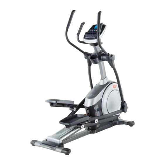
NORDICTRACK ® E 7.2 elliptical. The E 7.2 elliptical manual. To help us assist you, note the product model provides an impressive selection of features designed number and serial number before contacting us. The... -
Page 5: Part Identification Chart
PART IDENTIFICATION CHART Use the drawings below to identify the small parts needed for assembly. The number in parentheses below each drawing is the key number of the part, from the PART LIST near the end of this manual. The number following the key number is the quantity needed for assembly. -
Page 6: Assembly
ASSEMBLY •• Assembly requires two persons. •• In addition to the included tool(s), assembly requires the following tools: •• Place all parts in a cleared area and remove the one Phillips screwdriver packing materials. Do not dispose of the packing materials until you complete all assembly steps. - Page 7 3. With the help of a second person, place some of the packing materials (not shown) under the front of the Frame (1). Have the second per- son hold the Frame to prevent it from tipping while you complete this step. Attach the Front Stabilizer (6) to the Frame (1) with two M10 x 122mm Screws (104) and two M10 Split Washers (105).
- Page 8 5. Tip: Avoid pinching the Upper Wire (110). Avoid damaging the indicated plastic tabs. Avoid pinching the Upper Set the Upright (4) on the Frame (1). Wire (110) and avoid damaging the tabs Attach the Upright (4) with four M10 x 25mm Screws (92) and four M10 Split Washers (105).
- Page 9 7. Identify the Right Upper Body Arm (61), which is marked with a ““Right”” sticker, and orient it as shown. Slide the Right Upper Body Arm (61) onto the Right Upper Body Leg (60). Attach the Right Upper Body Arm (61) with two M8 x 38mm Bolts (96) and two M8 Locknuts (102).
- Page 10 9. Tip: Avoid pinching the wires. Attach the Console (7) to the Upright (4) with four M4 x 16mm Screws (101). Avoid pinching the wires 10. Identify the Right Pedal Arm (58), which is marked with a ““Right”” sticker, and orient it as shown.
- Page 11 11. Orient the Right Pedal Arm (58) as shown. Apply grease to the axle on the Right Pedal Arm (58). Attach the Right Pedal Arm (58) to the Right Roller Arm (59) with an M8 x 13mm Screw (82), a Small Axle Cover (55), and an M8 Washer (97).
- Page 12 13. Note: If you purchase the optional chest heart rate monitor (see page 24), see step 20 on page 15 to install the receiver included with the heart rate monitor. Orient the Rear Upright Cover (81) as shown. Attach the Rear Upright Cover (81) to the Upright (4) with four M4 x 16mm Screws (101).
- Page 13 15. Identify the Right Upper Body Leg Inner Cover (83), which is marked with a ““Right”” sticker, and orient it as shown. Attach the Right Upper Body Leg Inner Cover (83) to the Right Upper Body Leg (60) with an M4 x 16mm Screw (101) and an M5 Washer (32).
- Page 14 17. Orient the Rear Console Cover (80) as shown. Attach the Rear Console Cover (80) to the Upright (4) with two M4 x 16mm Screws (101). Orient the Front Console Cover (79) as shown. Attach the Front Console Cover (79) around the Upright (4) by pressing the hooks on the Rear Console Cover (80) onto the tabs on the Front Console Cover.
- Page 15 If you purchase the optional heart rate monitor (see page 24), follow the additional step below to install the receiver included with the heart rate monitor. 20. See steps 17 and 13. Remove the Front and Rear Console Covers (79, 80) if necessary. Then, remove the Front and Rear Upright Covers (117, 81) if necessary.
-
Page 16: How To Use The Elliptical
HOW TO USE THE ELLIPTICAL HOW TO PLUG IN THE POWER ADAPTER HOW TO MOVE THE ELLIPTICAL IMPORTANT: If the elliptical has been exposed to Due to the size and weight of the elliptical, moving cold temperatures, allow it to warm to room tem- it requires two persons. - Page 17 HOW TO CHANGE THE INCLINE OF THE RAMP To vary the motion of the pedals, you can change the Upper incline of the ramp. To raise the ramp, simply pull the Body Arms ramp handle upward to the desired incline level. Handlebars Latch Ramp...
- Page 18 CONSOLE DIAGRAM FEATURES OF THE CONSOLE The advanced console offers an array of features designed to make your workouts more effective and enjoyable. When you use the manual mode of the console, you can change the resistance of the pedals with the touch of a button.
- Page 19 HOW TO USE THE MANUAL MODE Distance (Dist.)——This display mode will show the distance that you have pedaled in miles or 1. Begin pedaling or press any button on the kilometers. console to turn on the console. Pulse——This display mode will show your heart rate When you turn on the console, the display will turn when you use the handgrip heart rate monitor or on.
- Page 20 As you exercise, the workout intensity level bar If there are will indicate the approximate intensity level of your sheets of plastic Contacts exercise. on the metal contacts on the handgrip heart rate monitor, remove the plastic. To mea- sure your heart rate, hold the Press the Home button to return to the default handgrip heart...
- Page 21 HOW TO USE AN ONBOARD WORKOUT At the end of each segment of the workout, a series of tones will sound and the next segment of 1. Begin pedaling or press any button on the the profile will begin to flash. If a different resis- console to turn on the console.
- Page 22 HOW TO USE AN IFIT LIVE WORKOUT workout of that type in your schedule. Press the Compete button to compete in a race that you have You must have an iFit Live module to use an iFit Live previously scheduled. For more information on workout.
- Page 23 HOW TO CHANGE CONSOLE SETTINGS If no module is connected, the display will show the words NO IFIT MODULE. If no module is con- The console features a user mode that allows you to nected, go to step 10. view usage information, select a unit of measurement, and adjust the contrast level of the display.
- Page 24 HOW TO USE THE SOUND SYSTEM THE OPTIONAL CHEST HEART RATE MONITOR To play music or audio books through the console Whether your sound system while you exercise, plug your audio goal is to cable into the jack on the console and into a jack on burn fat or to your MP3 player or CD player;...
-
Page 25: Maintenance And Troubleshooting
MAINTENANCE AND TROUBLESHOOTING I nspect and tighten all parts of the elliptical regularly. Note: For clarity, the left shield is shown removed in the Replace any worn parts immediately. drawing below. To clean the elliptical, use a damp cloth and a small Next, locate the Reed Switch (38). - Page 26 HOW TO ADJUST THE DRIVE BELT See EXPLODED DRAWING C on page 35. Remove the M4 x 19mm Screws (5) and the M4 x 48mm Screw If the pedals slip while you are pedaling, even while (107) from the Left and Right Shields (73, 74). Then, the resistance is adjusted to the highest level, the drive remove the Right Shield.
-
Page 27: Exercise Guidelines
EXERCISE GUIDELINES Burning Fat——To burn fat effectively, you must exer- WARNING: cise at a low intensity level for a sustained period of Before beginning this time. During the first few minutes of exercise, your or any exercise program, consult your physi- body uses carbohydrate calories for energy. - Page 28 SUGGESTED STRETCHES The correct form for several basic stretches is shown at the right. Move slowly as you stretch ——never bounce. 1. Toe Touch Stretch Stand with your knees bent slightly and slowly bend forward from your hips. Allow your back and shoulders to relax as you reach down toward your toes as far as possible.
- Page 29 NOTES...
- Page 30 NOTES...
-
Page 31: Part List
PART LIST Model No. NTEVEL77911.0 R0412A Key No. Qty. Description Key No. Qty. Description Frame Roller Rear Stabilizer Pedal Arm Rear Cap Ramp Large Axle Cover Upright 16mm Wave Washer M4 x 19mm Screw Small Axle Cover Front Stabilizer Roller Arm Bushing Console Arm Bearing Left Handlebar... - Page 32 Key No. Qty. Description Key No. Qty. Description M4 x 16mm Screw Drive Belt M8 Locknut M4 x 42mm Screw M6 x 12mm Screw M4 x 30mm Screw M10 x 122mm Screw Disc Ring M10 Split Washer Front Upright Cover Cover Mount Shield Cover Cap M4 x 48mm Screw...
-
Page 33: Exploded Drawing
EXPLODED DRAWING A Model No. NTEVEL77911.0 R0412A... - Page 34 EXPLODED DRAWING B Model No. NTEVEL77911.0 R0412A...
- Page 35 EXPLODED DRAWING C Model No. NTEVEL77911.0 R0412A...
-
Page 36: Ordering Replacement Parts
ORDERING REPLACEMENT PARTS To order replacement parts, please see the front cover of this manual. To help us assist you, be prepared to provide the following information when contacting us: •• the model number and serial number of the product (see the front cover of this manual) ••...
Need help?
Do you have a question about the E 7.2 and is the answer not in the manual?
Questions and answers