
Related Manuals for UTC Fire and Security interlogix TT3010


Summary of Contents for UTC Fire and Security interlogix TT3010
- Page 1 TT3010 TR3010 TT3010-R3 TR3010-R3 TT3020WDM TR3020WDM TT3020WDM-R3 TR3020WDM-R3 TT3030 TR3030 TT3030-R3 TR3030-R3 TT3030WDM TR3030WDM TT3030WDM-R3 TR3030WDM-R3 IFS Fiber Module Installation & Operation Instructions P/N 1062835 • REV B • ISS 01AUG11...
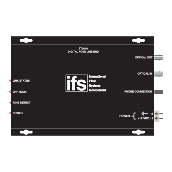
- Page 2 TT3010 DIGITAL POTS LINE END OPTICAL OUT OPTICAL IN International LINK STATUS Fiber Ring Systems Pin 4 Pin 3 Incorporated PHONE CONNECTION OFF-HOOK RING DETECT POWER Black wire POWER Black with +12 VDC - 1 white stripe Simplex multimode fiber optic cable TR3010 DIGITAL POTS TELEPHONE END OPTICAL OUT...
- Page 3 TT/TR3000 Link Status Off-Hook LED illuminates Ring Detect Power NOTE: All units set to USA/Canada standard. WORLD STANDARD JUMPER SETTINGS JUMPER SETTING STANDARD J7 J6 USA/CANADA AUSTRALIA JAPAN J6 J7 * UK includes the following countries: Austria, Belgium, Denmark, Finland, France, Germany, Greece, Iceland, Ireland, Italy, Luxembourg, Netherlands, Portugal, Spain, Sweden, Switzerland.
-
Page 4: Fcc Compliance
FCC Compliance This device complies with Part 15 of the FCC Rules. Operation is subject to the following two conditions: (1) This device may not cause harmful interference, and (2) this device must accept any interference received, including interference that may cause undesirable operation. Changes or modifications not expressly approved by International Fiber Systems, Inc. - Page 5 FCC Part 68 Registration Customer Information This equipment complies with Part 68 of the FCC rules and the requirements adopted by the ACTA. On the bottom of this equipment is a label that contains, among other information, a product identi er in the format US: FIBOT01BTT3000. If requested, this number must be provided to the telephone company.
- Page 6 PROPER MOUNTING METHOD FOR THE TT/TR3000 1) Locate unit on solid flat horizontal or vertical surface. 2) Position unit no closer than 24 inches from any power source or machinery. 3) Securely mount unit using (4) four mounting screws (not provided). 4) Select the correct voltage requirements for your application, +12VDC or 12VAC.
- Page 7 Product Disassembly Instructions for WEEE Per European Directive 2002/95/EC Waste Electrical and Electronic Equipment Required Tools: One number 2 Phillips (crosstip) screwdriver. One number 2 flat screwdriver. For the enclosed box version: 1. Locate and remove box cover securement screws. Usually, but not limited to at least 4 screws.
- Page 8 Contacting us For help installing, operating, maintaining, and troubleshooting this product, refer to this document and any other documentation provided. If you still have questions, contact us during business hours (Monday through Friday, excluding holidays, between 5 a.m. and 5 p.m. Pacific Time). Sales and support contact information North Toll-free: 855.286.8889 in the US, including Alaska and Hawaii;...
- Page 9 Copyright © 2011 UTC Fire & Security. All rights reserved. Trademarks and Interlogix and IFS names and logos are trademarks of patents UTC Fire & Security. Other trade names used in this document may be trademarks or registered trademarks of the manufacturers or vendors of the respective products.
Need help?
Do you have a question about the interlogix TT3010 and is the answer not in the manual?
Questions and answers