Table of Contents
Advertisement
FOR THE C572R RECUMBENT BIKE
1.1 INSTALLATION MANUAL..................................................................................
1.2 INSTALLATION INSTRUCTIONS.......................................................................
Remove the Front Lower Cover.........................................................
Disconnect Cables and Remove the Pedestal...................................
Remove the Left Pedal and Crank Cover...........................................
Install Cables......................................................................................
Organize Cables.................................................................................
Install the Left Side Cover and Pedal.................................................
Secure the Pedestal...........................................................................
Remove the Cutaway.........................................................................
Install the Integrated TV Module........................................................
STEP 10 Install the Adaptor Box.......................................................................
STEP 11 TV Angle Adjustment..........................................................................
FOR THE C572U RECUMBENT BIKE
2.1 INSTALLATION MANUAL..................................................................................
2.2 INSTALLATION INSTRUCTIONS.......................................................................
STEP 1 Remove the Pedestal and Front Lower Cover......................................
STEP 2 Disconnect Cables and Remove the Pedestal......................................
STEP 3 Install Cables.........................................................................................
STEP 4 Install the Seat Bottom and Pedals.......................................................
STEP 5 Remove the Cutaway............................................................................
STEP 6 Install the TV Module...........................................................................
STEP 7 Install the Adaptor Box.........................................................................
STEP 8 TV Angle Adjustment............................................................................
ANALOG TV) OPERATING MANUAL
3.1 TV Operating Instructions...................................................................................
3.2 CATV Function Settings......................................................................................
TABLE OF CONTENTS
1
2
4
6
7
8
9
10
11
12
13
16
17
18
19
21
23
24
25
26
27
30
31
33
34
Advertisement
Table of Contents

Subscribe to Our Youtube Channel
Related Manuals for SportsArt Fitness C572R


Summary of Contents for SportsArt Fitness C572R
-
Page 1: Table Of Contents
TABLE OF CONTENTS CHAPTER 1: CARDIO ACTIVE ENTERTAINMENT STATION (INTEGRATED TV) FOR THE C572R RECUMBENT BIKE 1.1 INSTALLATION MANUAL.................. 1.2 INSTALLATION INSTRUCTIONS............... STEP 1 Remove the Front Lower Cover............STEP 2 Disconnect Cables and Remove the Pedestal........STEP 3 Remove the Left Pedal and Crank Cover........... - Page 2 3.3 OSD Menu and keys in CATV Mode..............3.4 How to Perform the Search Function..............3.4.1 Search Function Illustrations - TV System............3.4.2 NTSC Cable Illustration..................3.4.3 TV Scan......................3.4.4 TV Channel Search in Progress............... 3.4.5 iPod Function....................3.5.1 iPod Function Illustrations – iPod System............3.5.2 iPod Function Illustrations –...
- Page 3 4.9 Other Notes......................4.9.1 DVB-T Menu..................... 4.9.2 Program Search....................4.9.3 Parental Control....................4.9.4 System Settings....................4.9.5 Games......................4.9.6 Accessory......................4.9.7 Personal Style....................4.10 Setup Menu Navigation..................4.11 DVB T Frequency Table and Country List............
-
Page 4: Chapter 1: Cardio Active Entertainment Station (Integrated Tv)
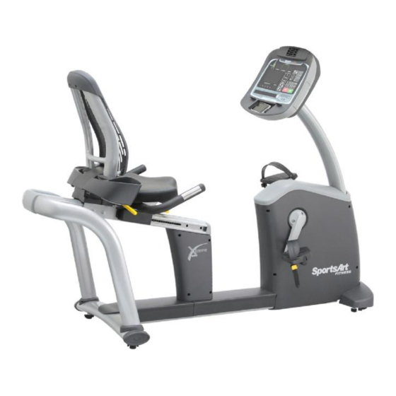
CHAPTER 1-CARDIO ACTIVE ENTERTAINMENT STATION (INTEGRATED TV) FOR THE C572R RECUMBENT BIKE 1.1 INSTALLATION MANUAL Install the CardioActive™ Entertainment Station (integrated TV) onto the SportsArt C572R cycle as follows. -
Page 5: Installation Instructions
1.2 INSTALLATION INSTRUCTIONS Parts in the Main Module Assembly Part Name Qty No. Part Name Coaxial cable splitter Integrated TV module Ground wire Owner's manual Lower cable TV lower power cord Zip tie TV adaptor Power switch Power cord F connector adapter... -
Page 6: Step 1 Remove The Front Lower Cover
STEP 1 Remove the Front Lower Cover... - Page 7 12*15 The CardioActive™ Entertainment Station is an integrated TV module for use on several SportsArt Fitness products. Please follow instructions below to install this integrated TV module on the C572R cycle. Note: For brevity, throughout this manual, the word “screws” is used where screws, washers, and other hardware may be involved.
- Page 8 (a) Remove the front lower cover as indicated by (A) and (B) below. Remove screws separately from the power terminal plate and the AV terminal plate. First, loosen the nut on the F connector adapter (A5) . From the front, secure the AV terminal plate.
-
Page 9: Step 2 Disconnect Cables And Remove The Pedestal
STEP 2 Disconnect Cables and Remove the Pedestal a) Remove screws from the display cover. (b) Disconnect cables in three places, A, B, and C. In area D, remove the two cables; these cables will not be needed. Remove the caps that cover screw heads on the pedestal. Then remove the screws from the pedestal. -
Page 10: Step 3 Remove The Left Pedal And Crank Cover
STEP 3 Remove the Left Pedal and Crank Cover (a) Remove the left pedal. (b) Remove the crank cover. c) Remove screws from the left side cover. (d) Rotate the crank 180 degrees until it points upward vertically as shown. (e) Lift the left side cover off, tilting it to avoid the crank and the product frame. -
Page 11: Step 4 Install Cables
STEP 4 Install Cables (a) From the hole in the display cover, thread the TV lower power cable (A3) and lower cable (A8) into the pedestal. Then thread the cables through the unit, and out the hole at the left side as shown. (b) Lift the pedestal. -
Page 12: Step 5 Organize Cables
STEP 5 Organize Cables (a) After connecting cable (A3), cable (A8), the power switch, and the F connector adapter (A5) , secure the power switch bracket onto the unit as shown. (b) Starting at the power switch bracket side, organize cables. Use zip ties (A9) to secure the cables to the frame as shown. -
Page 13: Step 6 Install The Left Side Cover And Pedal
STEP 6 Install the Left Side Cover and Pedal (a) Hold the crank up while slipping the left side cover into place. (b) Turn the crank 180 degrees, so it hangs downward. (c) Secure left side cover screws. (d) Put the crank cover back into place. (e) Secure the left pedal back into place. -
Page 14: Step 7 Secure The Pedestal
STEP 7 Secure the Pedestal (a) Secure the pedestal screws and their caps. (b) Put the front lower cover into place, following sequence (A), then (B). -
Page 15: Step 8 Remove The Cutaway
STEP 8 Remove the Cutaway Remove the cutaway to allow for installation of the TV module. (a) Remove the sticker from the top of the fan cover. (b) Use a pair of wire cutters to remove the cutaway in area A. -
Page 16: Step 9 Install The Integrated Tv Module
STEP 9 Install the Integrated TV Module Follow steps (a) through (f) to install the TV module. (a) Before installing the integrated TV module (A1), carefully cut the zip tie off the coil of cables. From above the cutaway area, align the integrated TV module (A1) with the guide tube. - Page 17 (c) Secure the coaxial cable splitter (A6) onto the display lower cover. Then connect integrated TV module (A1) CATV(1) and DTV(2) cables and the lower cable (A8) to the splitter (A6). Then use the upper screw on the coaxial cable splitter (A6) to secure the ground wire (A7) and the ground wire from the black connector cable (3) of the integrated TV module (A1).
- Page 18 (d) Connect the integrated TV (A1) cables (4) and the TV lower power cable (A3). (e) Connect the integrated TV screen (A1) black connector cable (3) and iPod encoder board from the display. Connect the white connector cable (5) to the display board.
-
Page 19: Step 10 Install The Adaptor Box
STEP 10 Install the Adaptor Box Route the adaptor cord under the front of the cycle, insert it into the adaptor (A4), and insert the main power cord from the adaptor box into the power outlet , and insert it into the power cord (A9) -
Page 20: Step 11 Tv Angle Adjustment
STEP 11 TV Angle Adjustment To secure the angle of the TV screen at its recommended position, follow instructions on the sticker (inside the neck cover). To secure the TV screen angle at a different position, follow steps (a) through (d) below. (a) Remove the integrated TV module neck cover. -
Page 21: Chapter 2: Cardio Active Entertainment Station (Integrated Tv)
CHAPTER 2-CARDIO ACTIVE ENTERTAINMENT STATION (INTEGRATED ) FOR THE C572U RECUMBENT BIKE 2.1 INSTALLATION MANUAL Install the CardioActive™ Entertainment Station (integrated TV) onto the SportsArt C572U cycle as follows. -
Page 22: Installation Instructions
2.2 INSTALLATION INSTRUCTIONS Parts in the Main Module Assembly Part Name Qty No. Part Name Coaxial cable splitter Integrated TV module Ground wire Owner's manual Lower cable TV lower power cord TV adaptor Power cord Power switch F connector adapter... - Page 23 12*15 The CardioActive™ Entertainment Station is an integrated TV module for use on several SportsArt Fitness products. Please follow instructions below to install this integrated TV module on the C572U cycle. Note: For brevity, throughout this manual, the word “screws” is used where screws, washers, and other hardware may be involved.
-
Page 24: Step 1 Remove The Pedestal And Front Lower Cover
STEP 1 Remove the Pedestal and Front Lower Cover... - Page 25 (a) Remove the front lower cover as indicated by (A), (B), and (C) below. (b) Remove screws separately from the power terminal plate and the AV terminal plate. First, loosen the nut on the F connector adapter (A5) . From the front, secure the AV terminal plate.
-
Page 26: Step 2 Disconnect Cables And Remove The Pedestal
STEP 2 Disconnect Cables and Remove the Pedestal (a) Remove screws from the display cover. (b) Disconnect cables in three places, A, B, and C. In area D, remove the two cables; these cables will not be needed. Remove the caps that cover screw heads on the pedestal. Then remove the screws from the pedestal. -
Page 27: Step 3 Install Cables
STEP 3 Install Cables (a) From the hole in the display cover, thread the TV lower power cable (A3) and lower cable (A8) into the pedestal. Then thread the cables through the product, out the hole as shown. Note: Do not allow the top end of the cable to fall into the unit. -
Page 28: Step 4 Install The Seat Bottom And Pedals
STEP 4 Install the Seat Bottom and Pedals (a) Secure pedestal screws into pedestals and secure the screw head caps. (b) Connect cable (A3), cable (A8), the power switch, and the F connector adapter (A5) . Secure the power switch bracket to the unit as shown. Secure covers in order (A), (B), and (C). -
Page 29: Step 5 Remove The Cutaway
STEP 5 Remove the Cutaway (a) Remove the sticker from the top of the fan cover. (b) Use a pair of wire cutters to remove the cutaway in area A. -
Page 30: Step 6 Install The Tv Module
STEP 6 Install the TV Module Follow steps (a) through (f) to install the TV module. (a) Before installing the integrated TV module (A1), carefully cut the zip tie off the coil of cables. From above the cutaway area, align the integrated TV module (A1) with the guide tube. - Page 31 (c) Secure the coaxial cable splitter (A6) onto the display lower cover. Then connect integrated TV module (A1) CATV(1) and DTV(2) cables and the lower cable (A8) to the splitter (A6). Then use the upper screw on the coaxial cable splitter (A6) to secure the ground wire (A7) and the ground wire from the black connector cable (3) of the integrated TV module (A1).
- Page 32 (d) Connect the integrated TV (A1) cables (4) and the TV lower power cable (A3). (e) Connect the integrated TV screen (A1) black connector cable (3) and iPod encoder board from the display. Connect the white connector cable (5) to the display board.
-
Page 33: Step 7 Install The Adaptor Box
STEP 7 Install the Adaptor Box Route the adaptor cord under the front of the cycle, insert it into the adaptor (A4), and insert the main power cord from the adaptor box into the power outlet, and insert it into the power cord (A9) -
Page 34: Step 8 Tv Angle Adjustment
STEP 8 TV Angle Adjustment To secure the angle of the TV screen at its recommended position, follow instructions on the sticker (inside the neck cover). To secure the TV screen angle at a different position, follow steps (a) through (d) below. a) Remove the integrated TV module neck cover. - Page 35 CHAPTER 3- CardioActive™ Entertainment Station – Integrated Analog TV Operating Manual...
-
Page 36: Chapter 3: Cardio Active Entertainment Station
CHAPTER 3-CARDIO ACTIVE ENTERTAINMENT STATION (INTEGRATED ANALOG TV) 3.1 TV Operating Instructions Power switch 1. Press the POWER key to turn on the unit. A green LED on the power switch will light up. (A red LED lights when the unit is not activated.) 2. -
Page 37: Catv Function Settings
3.2 CATV Function Settings Connect the analog source cable as shown in Figure (1). Press the source key until 「 」 CATV appears in the upper left corner, as shown in Figure (2). 3.3 OSD Menu And Keys in CATV Mode In the CATV mode, after pressing the MENU key, the OSD menu will appear, and key definitions will change. - Page 38 (b) In the secondary OSD window: The MENU key will become the OK key, used for confirmation. The CH+/- key will become the UP/DOWN key. The VOL- key will become the EXIT key. If no keys are pressed, the OSD screen will disappear. You can also press the VOL-key to return to the main OSD window.
- Page 39 OSD Secondary Window OSD Adjustment Brightness Example 2 Image H position Image V position...
-
Page 40: How To Perform The Search Function
3.4 How to Perform the Search Function 1. Press the MENU key to enter the OSD window. 2. Press the CH- key to select the SYSTEM setting function. 3. Press the OK (MENU) key to enter the system setting mode. 4. -
Page 41: Ntsc Cable Illustration
3.4.2 NTSC Cable Illustration NTSC Cable 3.4.3 TV Scan... -
Page 42: Tv Channel Search In Progress
3.4.4 TV Channel Search in Progress 3.4.5 iPod Function When you have purchased and installed the iPod option but cannot activate iPod functions via the Source key, please use the following procedure to activate these functions. 1. Press the Source key to select the CATV mode. 2. -
Page 43: Ipod Function Illustrations - Ipod System
3.5.1 iPod Function Illustrations – iPod System 3.5.2 iPod Function Illustrations – iPod ON SystemSetting AspecRatio Full Screen Color Temperature 6500k Channel Display Language English TV ystem NTSC Cable ▶ TV Scan DTV ystem iPod System... -
Page 44: Ipod Function Illustrations - Source Key
3.5.3 iPod Function Illustrations – Source Key 「 」 Connect the iPod. Press the Source key until iPod appears in the upper left corner. iPod Menu Vol- Vol+ Source Power Note: When the TV is not on, you can listen to music on the iPod. If you press the VOL+/- key,you can turn on the TV to see the iPod image screen. -
Page 45: Osd Menu, Other Functions - Video
3.6.1 OSD Menu, Other Functions - Video Video setting functions include the following: Brightness adjustment Contrast adjustment Saturation Sharpness Image H position (horizontal picture adjustment) Image V position (vertical picture adjustment) Default (factory setting) Video Setting Brightness Contrast Saturation Sharpness Image H position ▶... -
Page 46: Osd Menu, Other Functions - Audio
3.6.2 OSD Menu, Other Functions - Audio Audio setting functions include the following: Volume Mute Audio Setting Volume Mute 3.6.3 OSD Menu, Other Functions - System System setting functions include the following: Aspect ratio Color temperature Channel display -- OSD MENU display Language selection TV system selection (NTSC, PAL…) TV scan... - Page 47 SystemSetting AspecRatio Full Screen Color Temperature 6500k Channel Display Language English NTSC Cable TV ystem ▶ TV Scan DTV ystem iPod System...
-
Page 48: Osd Menu, Other Functions - Dtv
3.6.4 OSD Menu, Other Functions - DTV When you have purchased and installed the DTV option but cannot activate DTV functions via the Source key, please use the following procedure to activate these functions. 1. Press the Source key to select the CATV mode. 2. - Page 49 - CHAPTER 4 CardioActive™ Entertainment Station – Integrated Digital TV Operating Manual...
-
Page 50: Chapter 4: Cardio Active Entertainment Station - Integrated Digital Tv
CHAPTER 4-CARDIO ACTIVE ENTERTAINMENT STATION (INTEGRATED DIGITAL TV) Integrated digital TV is optional and may not be included in your particular model. If your bike is equipped with these functions, please note the following information. OPERATING INSTRUCTIONS 4.1 Digital TV System Cable Connections Connect cables for digital TV signal reception as follows. -
Page 51: Dtv Atsc-Usa Digital Tv Functions
( ) 4.3 DTV ATSC-USA Digital TV Functions Follow instructions below to activate the On Screen Display (OSD) MENU for the DTV system: 1. Press the Source key until DTV appears in the upper left corner of the TV screen. 2. - Page 52 System Setting AspecRatio Full Screen Color Temperature 6500k Channel Display Language English TV System NTSC Cable TV Scan DTV System ATSC iPod System...
-
Page 53: Dtv Mode Operation
4.4 DTV Mode 4.4.1 DTV Mode Press the Source key to select DTV mode. Menu Vol- Power Vol+ Source 4.4.2 ATSC Menu In the DTV mode, hold the Source key for five seconds to enter the ATSC digital TV system menu. Main Menu Auto Search CH setup... -
Page 54: Introduction To The Atsc Menu
4.5 Introduction to the ATSC Menu Auto search includes the following functions: ˙ Source Type allows selection of source, either antenna or cable. ˙ Start Search -- begins channel search. ˙ Reset resets to factory default settings. ˙ SNR (signal to noise ratio). 4.6 Auto Search Operation 4.6.1 DTV Menu... -
Page 55: Scan Window
4.6.2 Scan Window Searching Digital channels Source type [Antenna] Searching is in process now Please wait….. To stop press [EXIT] Found 0 Digital channels Menu Vol- Power Vol+ Source 4.6.3 Channel Search Completed Window Channel Search Completed Found ** Digital channels This screen will automatically disappear. - Page 56 DTV Screen Menu Vol- Source Power Vol+ Note: After the channel scan is completed, please press the Source key to ensure that keys resume their original functions. During the channel scan process, do not press any keys. Otherwise, the scan process might not finish completely. Note: In DTV mode, if the channel scan message appears automatically, hold the Source key for five seconds.
-
Page 57: Channel Scan
4.6.4 Channel Scan After selecting the YES key, the channel scan window appears as below. Searching Digital channels Source type [Antenna] Searching is in process now Please wait….. To stop press [EXIT] Found 0 Digital channels Menu Vol- Source Power Vol+ Note: During the channel scan process, please do not press any keys. -
Page 58: Dtv Dvb-T (European) Digital Tv Functions
( ) 4.7 DTV DVB-T (European) Digital TV Functions Note DTV SYSTEM OSD MENU operation: 1. Press the Source key until DTV appears in the upper left corner. 2. Press the “MENU” key to enter the OSD window. 3. Press the CH- key to select the SYSTEM Setting function. 4. -
Page 59: The System Setup Process
4.8 The System Setup Process The system setup includes two steps: establishing the country setting, and establishing the OSD language setting. 4.8.1 Country Setting The DVB-T system has 3 types of frequencies: 6/7/8MHz. Different signals are used in different areas, so during initial setup, country code must be established, before the channel scan process can be performed. - Page 60 Main Menu Program List Program Search Parental Control System Setting Accessory Personal Style Vo l + Menu Vol- Source Power System Setting TV Standard Display Type Video Output Antenna Power Regional Setting Language Time Setting System Schedule Vo l + Menu Vol- Power...
- Page 61 Regional Setting ◀ TWN ▶ Country OSD Language English Time Zone GMT 8 00 Use VOL or VOL to select country. Vo l - Vo l + Menu Source Power Regional Setting Country OSD Language ◀ English▶ Time Zone GMT 8 00 Use VOL or VOL to select OSD language.
- Page 62 Press Source Exit to exit DTV MENU. Vo l - Vo l + Menu Source Power Note: At this point, to establish other DTV system settings, or if you need to redo settings, hold the Source key for five seconds until the DTV Menu appears. Then follow instructions above.
-
Page 63: Channel Search
4.8.2 Channel Search Follow instructions below to perform a channel scan Hold the Source key for five seconds to enter the DTV Menu. ( ) 2. Select Program Search. Then press the MENU OK key to confirm your choice. 3. After entering the Program Search menu, select Automatic Search. 4. - Page 64 Program Search Automatic Search Manual Search Vo l + Vo l - Menu Source Power Do you want to start Auto Search? Cancel Vo l + Vo l - Menu Source Power Do you want to erase your previous channel list? Vo l - Vo l + Menu...
- Page 65 Automatic Search Progress Channel No XX TV List Music List Vo l - Vo l + Menu Source Power DTV Screen Vo l + Vo l - Menu Source Power...
-
Page 66: Other Notes
4.9 Other Notes 4.9.1 DVB-T Menu Program List includes the following: 1. TV Program List 2. Music Program List Sort a. By name b. By Service ID c. By Channel Program List TV Program List Music Program List Sort Vo l - Vo l + Menu Source... -
Page 67: Parental Control
4.9.3 Parental Control ˙ This program is not activated because it requires a password. ˙ Channel lock ˙ Parental Setting (Restricts channels) ˙ Change Pin (Change the pin number) Parental Control Channel lock Parental Setting Change Pin Vo l - Vo l + Menu Source... -
Page 68: Games
4.9.5 Game Game selections include the following: ˙ Mine ˙ Tetris ˙ Gomoku ˙ Calendar Game Mine T etris Gomoku Calendar Vo l - Vo l + Menu Source Power 4.9.6 Accessory Accessories include the following: ˙ System information (version number) ˙... -
Page 69: Personal Style
4.9.7 Personal Style Personal style settings include the following: ˙ Menu Color ˙ Transparency Level ˙ Border Pattern ˙ Entry Animation Personal Style ◀ Blue ▶ Menu Color Transparency Level Border Pattern Round Entry Animation Right Vo l - Vo l + Menu Source Power... -
Page 70: Setup Menu Navigation
4.10 Setup Menu Navigation Program List Sort TV Program List By Name Music Program List ▶ By Service ID Sort By Channel No. Program Search Automatic Search Manual Search TV Standard Parental Control NTSC AUTO Channel Lock ▶ Parental Setting Change Pin Display Type ︰... -
Page 71: Dvb T Frequency Table And Country List
4.11 DVB T Frequency Table and Country List Band Switch Country 177 0 . ~213 0MHz Argentina . MHz Taiwan 473 0 803 0 177.5~ 226 5 . MHz 529 5 . ~816 5 MHz Australia 7M & 8M 177.5~ 226 5 . MHz 474 0 . ~858 0 MHz Deutschland 474 0 .
Need help?
Do you have a question about the C572R and is the answer not in the manual?
Questions and answers